Mitsubishi Outlander: Wireless Control Module (WCM)
General Information
The wireless control module (WCM) is a system that integrates the keyless entry function, with which remote operation (opening/closing of all doors and the liftgate and operation of warning function that warns a person who intends to damage the vehicle *), can be performed by operating the lock/unlock button or panic button on the ignition key (transmitter).
Also, WCM incorporates the immobilizer function, which prohibits the starting of engine using an unauthorized key, and the tire pressure monitoring system (TPMS), which issues a warning to a driver by illuminating or flashing the warning light if an abnormality to the tire pressure is detected. WCM has the following features:
- The ignition key has an indicator light that enables the driver to check if the signal is transmitted correctly or if the battery in the key is discharged.
- Each vehicle is provided with two ignition keys, and up to eight ignition keys can be registered.
- Settings of the keyless entry function can be adjusted using a customization function.
NOTE: *: Horn sounds, and headlights and taillights flash.
CONSTRUCTION DIAGRAM
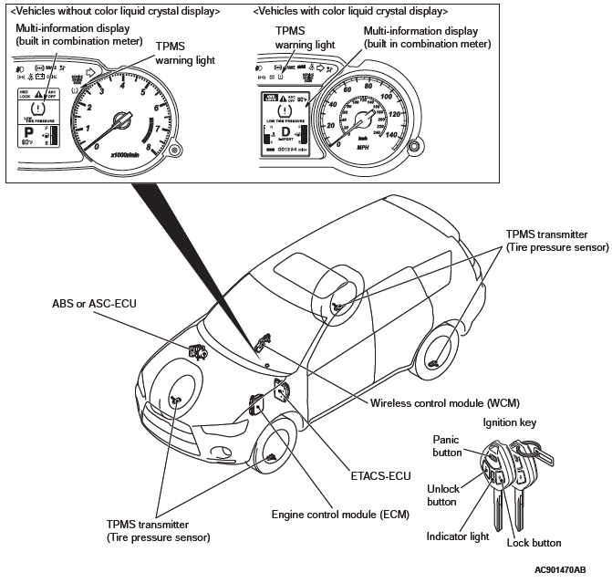
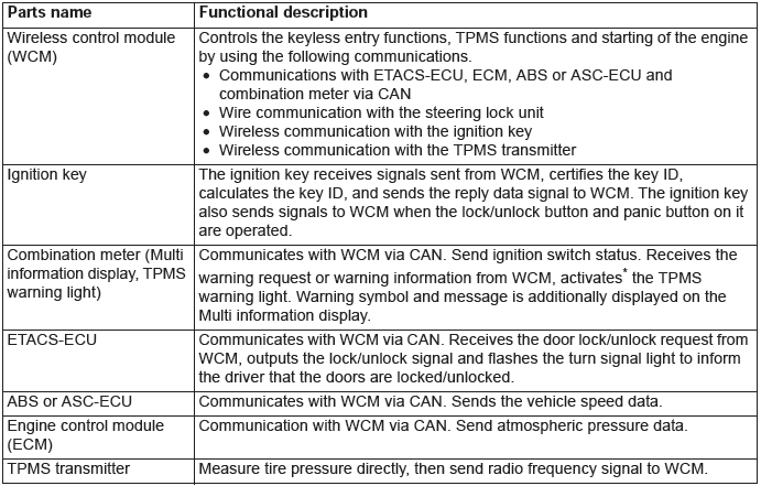
Main components and functions
NOTE:
- *: Illuminates for tire pressure warning.
- *: Flashes for about 1 minute and then continuously illuminated for TPMS malfunction warning.
System configuration
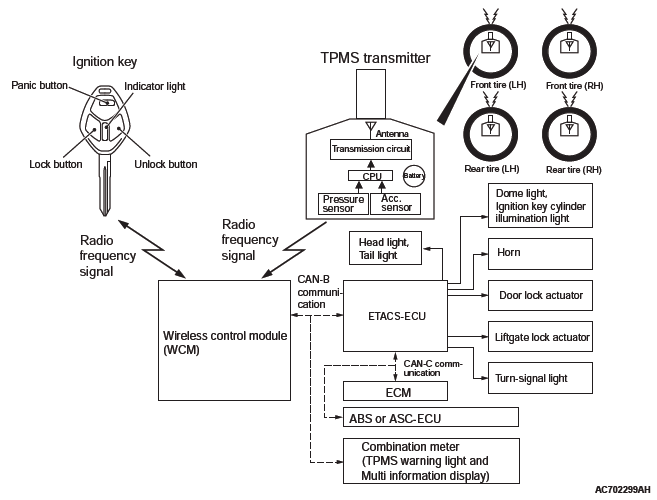
NOTE: In case of replacement of WCM, all keyless ID, key ID and tire pressure sensor ID should be re-registered using scan tool MB991958 (M.U.T.-III sub-assembly).
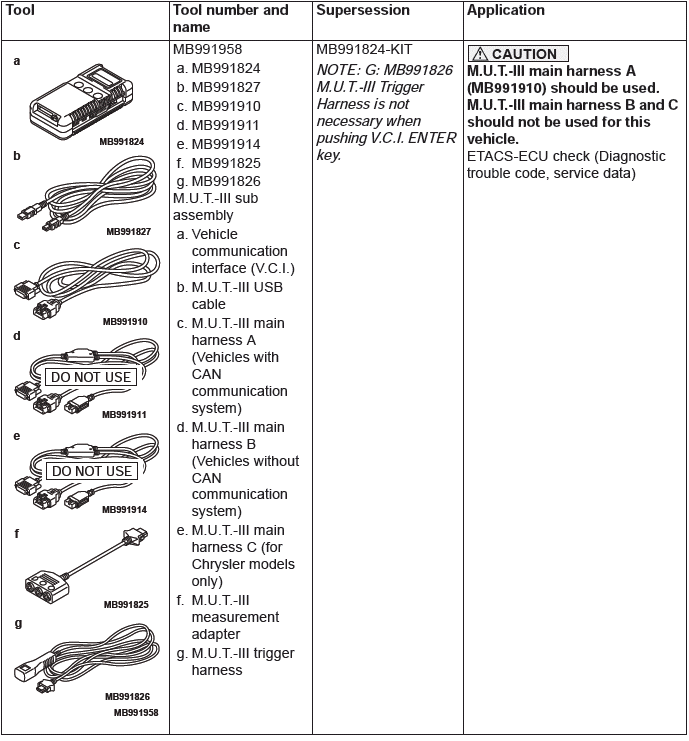
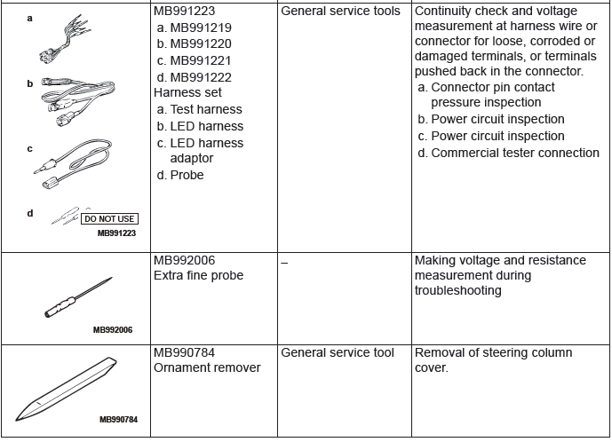
Special Tools
READ NEXT:
 Diagnosis
STANDARD FLOW OF DIAGNOSTIC
TROUBLESHOOTING
Refer to GROUP 00 − How to Use Troubleshooting/Inspection
Service Points, Contents of Troubleshooting.
DIAGNOSTIC FUNCTION
HOW TO CONNECT THE SCAN TO
DTC B1731, B1761, B1A08, B1A09, B1A0A, B1A0B, B1A0C, B1A0D, B1A0E, B1A0F,
B1A10, B1A11, B1A12, B1A13, B1A14, B1A15, B1A16, B1A17, B1A24, B1A25, B1A28,
B1A35, B2101, B2102
DTC B1731: Engine control module communication timeout
CAUTION
When the DTC B1731 is set, be sure to diagnose
the CAN bus line.
When replacing the ECU, always check that
the communication circuit
DTC B2204, B2206, B2352, B2416, C1608, C1910, C1920, C1930, C1940, C1911,
C1921, C1931, C1941, C1912, C1922, C1932, C1942, C1913, C1923, C1933, C1943,
C1914, C1924, C1934, C1944
DTC B2204: Coding data mismatch
CAUTION
When DTC B2204 is set, be sure to diagnose
the CAN bus line.
When replacing the ECU, always check that
the communication circuit is normal.
DTC SET CONDIT
SEE MORE:
Basic Brake System
Diagnosis
INTRODUCTION TO BASIC BRAKE SYSTEM DIAGNOSIS
Hydraulic brakes are composed of the brake pedal,
master cylinder, brake booster and disc brakes. Malfunctions
such as insufficient braking power or the
generation of noise may occur due to wear, damage
or incorrect adjustment of these components.
BASIC B
On-vehicle Service
CHECK AT A/C-ECU TERMINAL
1. Disconnect the A/C compressor clutch connector to the A/C
compressor clutch.
2. Connect positive battery voltage directly to the connector for
the A/C compressor clutch.
3. If the A/C compressor clutch is normal, there will be a "click".
If the pulley and armature do
