Mitsubishi Outlander: Automatic Air Conditioning
General Information
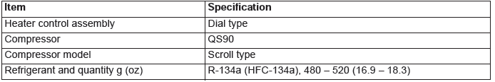
The blower, heater, and evaporator have been integrated with the heater and A/C system to achieve greater fan power and noise reduction.
SAFETY PRECAUTIONS
WARNING Wear safety goggles and gloves when servicing the refrigeration system to prevent severe damage to eyes and hands.
Because R-134a refrigerant is a hydro fluorocarbon (HFC) which contains hydrogen atoms in place of chlorine atoms, it will not cause damage to the ozone layer.
Ozone filters out harmful radiation from the sun. To assist in protecting the ozone layer, Mitsubishi Motors Corporation recommends an R-134a refrigerant recycling device.
Refrigerant R-134a is transparent and colorless in both the liquid and vapor state. Since it has a boiling point of −29.8ºC (−21.64ºF) at atmospheric pressure, it will be a vapor at all normal temperatures and pressures.
The vapor is heavier than air, non-flammable, and non-explosive. The following precautions must be observed when handling R-134a.
WARNING Do not heat R-134a above 40ºC (104.0ºF) or it may catch fire and explode.
R-134a evaporates so rapidly at normal atmospheric pressures and temperatures that it tends to freeze anything it contacts. For this reason, extreme care must be taken to prevent any liquid refrigerant from contacting the skin and especially the eyes. Always wear safety goggles when servicing the refrigeration part of the A/C system. Keep a bottle of sterile mineral oil handy when working on the refrigeration system.
1. Should any liquid refrigerant get into your eyes, use a few drops of mineral oil to wash them out. R-134a is rapidly absorbed by the oil.
2. Next, splash your eyes with plenty of cold water.
3. Call your doctor immediately even if irritation has ceased.
CAUTION Keep R-134a containers upright when charging the system.
In most instances, moderate heat is required to bring the pressure of the refrigerant in its container above the pressure of the system when charging or adding refrigerant.
A bucket or large pan of hot water not over 40ºC (104.0ºF) is all the heat required for this purpose. Do not heat the refrigerant container with a blow torch or any other means that would raise temperature and pressure above this temperature. Do not weld or steam-clean on or near the system components or refrigerant lines.
WARNING The leak detector for R-134a should be used to check for refrigerant gas leaks.
CAUTION Do not allow liquid refrigerant to touch bright metal or it will be stained.
When metering R-134a into the refrigeration system, keep the supply tank or cans in an upright position. If the refrigerant container is on its side or upside down, liquid refrigerant will enter the system and damage the compressor.
Refrigerant will tarnish bright metal and chrome surfaces, and in combination with moisture can severely corrode all metal surfaces.
OPERATION
CONDENSER FAN AND RADIATOR FAN CONTROL
The ECM judges the required revolution speed of radiator fan motor and condenser fan motor using the input signals transmitted from A/C switch, output shaft speed sensor and engine coolant temperature sensor.
COMPRESSOR CONTROL
When operating the A/C switch
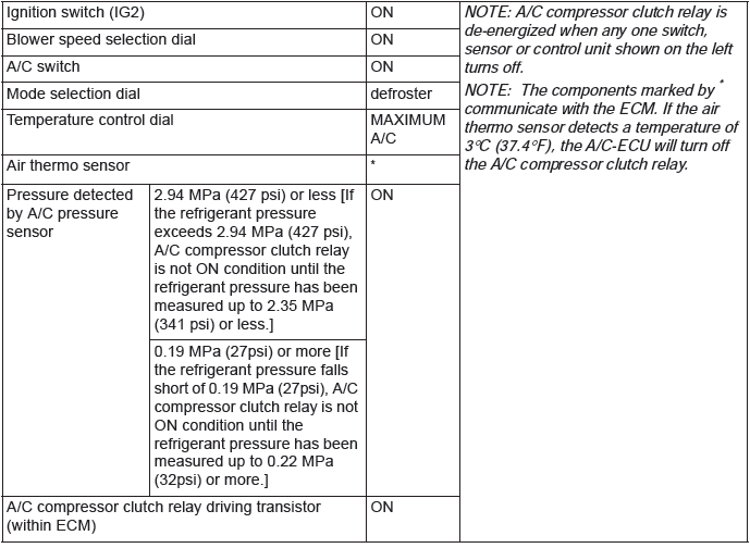
- The air thermo sensor, which senses the temperature of the air flowing out of the evaporator, deactivates the compressor at 3ºC (37.4ºF) or below.
- The A/C pressure sensor turns OFF when the refrigerant pressure becomes excessively high or low, thus protecting the compressor circuit (See Table below).
- When the air thermo sensor is activated, and the ignition switch, blower switch, and A/C switch are ON, the A/C compressor clutch relay is energized.
When operating the mode selection dial
- The A/C will work when the mode selection dial is set to the "Defroster" or "Defroster/foot" position, or the temperature control dial is set to the "MAXIMUM A/C" position. In other dial positions, when the A/C switch is turned on, the A/C will work.
A/C Compressor Clutch Relay ON Conditions
Automatic A/C Diagnosis
INTRODUCTION
After air is taken in through the damper, it is fed to the evaporator by the blower fan and motor and cooled. The air cooled by the air mix damper is mixed appropriately with the warmed air to achieve a comfortable temperature. If the A/C does not operate or the cooled air is not discharged, the system components or relay may be faulty.
AUTOMATIC A/C TROUBLESHOOTING STRATEGY
Use these steps to plan your diagnostic strategy. If you follow them carefully, you will be sure that you have exhausted most of the possible ways to find a heater, air conditioning and ventilation fault.
1. Gather information from the customer.
2. Verify that the condition described by the customer exists.
3. Find the malfunction by following the Symptom Chart.
4. Verify malfunction is eliminated.
DIAGNOSTIC FUNCTION
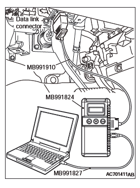
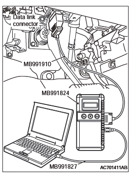
HOW TO CONNECT THE SCAN TOOL (M.U.T.-III)
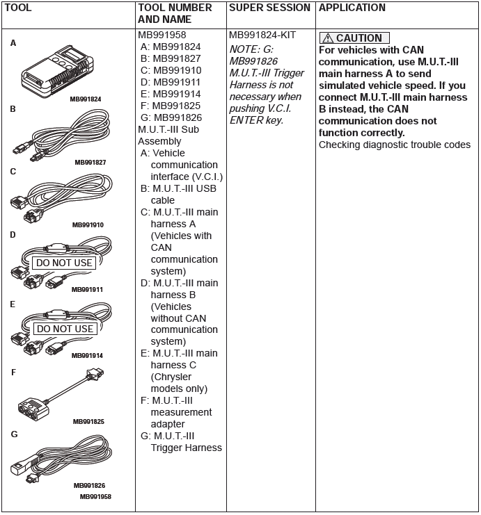
Required Special Tools:
- MB991958: Scan Tool (M.U.T.-III Sub Assembly)
- MB991824: Vehicles Communication Interface (V.C.I.)
- MB991827: M.U.T.-III USB Cable
- MB991910: M.U.T.-III Main Harness A (Vehicles with CAN communication system)
CAUTION To prevent damage to scan tool MB991958, always turn the ignition switch to the "LOCK" (OFF) position before connecting or disconnecting scan tool MB991958.
1. Ensure that the ignition switch is at the "LOCK" (OFF) position.
2. Start up the personal computer.
3. Connect special tool MB991827 to special tool MB991824 and the personal computer.
4. Connect special tool MB991910 to special tool MB991824 5. Connect special tool MB991910 to the data link connector.
6. Turn the power switch of special tool MB991824 to the "ON" position.
NOTE: When the special tool MB991824 is energized, the special tool MB991824 indicator light will be illuminated in a green color.
7. Start the M.U.T.-III system on the personal computer.
NOTE: Disconnecting scan tool MB991958 is the reverse of the connecting sequence, making sure that the ignition switch is at the "LOCK" (OFF) position.
HOW TO READ AND ERASE DIAGNOSTIC TROUBLE CODES
Required Special Tools:
- MB991958: Scan Tool (M.U.T.-III Sub Assembly)
- MB991824: Vehicles Communication Interface (V.C.I.)
- MB991827: M.U.T.-III USB Cable
- MB991910: M.U.T.-III Main Harness A (Vehicles with CAN communication system)
CAUTION To prevent damage to scan tool MB991958, always turn the ignition switch to the "LOCK" (OFF) position before connecting or disconnecting scan tool MB991958.
NOTE: If the battery voltage is low, diagnostic trouble codes will not be set. Check the battery if scan tool MB991958 does not display.
1. Connect the scan tool MB991958 to the data link connector.
2. Turn the ignition switch to the "ON" position.
3. Select "System select" from the start-up screen.
4. Select "From 2006 MY" of "Model Year". When the "Vehicle Information" is displayed, check the contents.
5. Select "Air Conditioner" from "System List", and press the "OK" button.
NOTE: When the "Loading Option Setup" list is displayed, check the applicable item.
6. Select "Diagnostic Trouble Code" to read the DTC.
7. If a DTC is set, it is shown.
8. Choose "Erase DTCs" to erase the DTC.
HOW TO READ DATA LIST
Required Special Tools:
- MB991958: Scan Tool (M.U.T.-III Sub Assembly)
- MB991824: Vehicles Communication Interface (V.C.I.)
- MB991827: M.U.T.-III USB Cable
- MB991910: M.U.T.-III Main Harness A (Vehicles with CAN communication system)
CAUTION To prevent damage to scan tool MB991958, always turn the ignition switch to the "LOCK" (OFF) position before connecting or disconnecting scan tool MB991958.
1. Connect the scan tool MB991958 to the data link connector.
2. Turn the ignition switch to the "ON" position.
3. Select "System select" from the start-up screen.
4. Select "From 2006 MY" of "Model Year". When the "Vehicle Information" is displayed, check the contents.
5. Select "Air Conditioner" from "System List", and press the "OK" button.
NOTE: When the "Loading Option Setup" list is displayed, check the applicable item.
6. Select "Data List".
7. Choose an appropriate item and select the "OK" button.
HOW TO PERFORM ACTUATOR TEST
Required Special Tools:
- MB991958: Scan Tool (M.U.T.-III Sub Assembly)
- MB991824: Vehicles Communication Interface (V.C.I.)
- MB991827: M.U.T.-III USB Cable
- MB991910: M.U.T.-III Main Harness A (Vehicles with CAN communication system)
CAUTION To prevent damage to scan tool MB991958, always turn the ignition switch to the "LOCK" (OFF) position before connecting or disconnecting scan tool MB991958.
1. Connect the scan tool MB991958 to the data link connector.
2. Turn the ignition switch to the "ON" position.
3. Select "System select" from the start-up screen.
4. Select "From 2006 MY" of "Model Year". When the "Vehicle Information" is displayed, check the contents.
5. Select "Air Conditioner" from "System List", and press the "OK" button.
NOTE: When the "Loading Option Setup" list is displayed, check the applicable item.
6. Select "Actuator Test".
7. Choose an appropriate item and select the "OK" button.
HOW TO DIAGNOSE THE CAN BUS LINE
Required Special Tools:
- MB991958: Scan Tool (M.U.T.-III Sub Assembly)
- MB991824: Vehicles Communication Interface (V.C.I.)
- MB991827: M.U.T.-III USB Cable
- MB991910: M.U.T.-III Main Harness A (Vehicles with CAN communication system)
CAUTION To prevent damage to scan tool MB991958, always turn the ignition switch to the "LOCK" (OFF) position before connecting or disconnecting scan tool MB991958.
1. Connect scan tool MB991958 to the data link connector.
2. Turn the ignition switch to the "ON" position.
3. Select "CAN bus diagnosis" from the start-up screen.
4. When the vehicle information is displayed, confirm that it matches the vehicle whose CAN bus lines will be diagnosed.
- If they match, go to Step 8.
- If not, go to Step 5.
5. Select "view vehicle information" button.
6. When the vehicle information is displayed, confirm again that it matches the vehicle which is being diagnosed.
- If they match, go to Step 8.
- If not, go to Step 5.
7. Press the "OK" button.
8. When the options are displayed, choose the options (mark the check) and then select "OK".
CHECK OF FREEZE FRAME DATA
The freeze frame data can be checked by using the scan tool.
When detecting fault and storing the DTC, the ECU connected to CAN bus line obtains the data before the determination of the DTC and the data when the DTC is determined, and then stores the ECU status of that time. By analyzing the data from scan tool, the troubleshooting can be performed more efficiently.
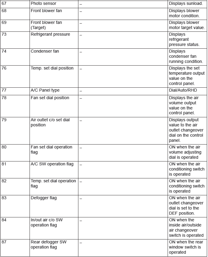
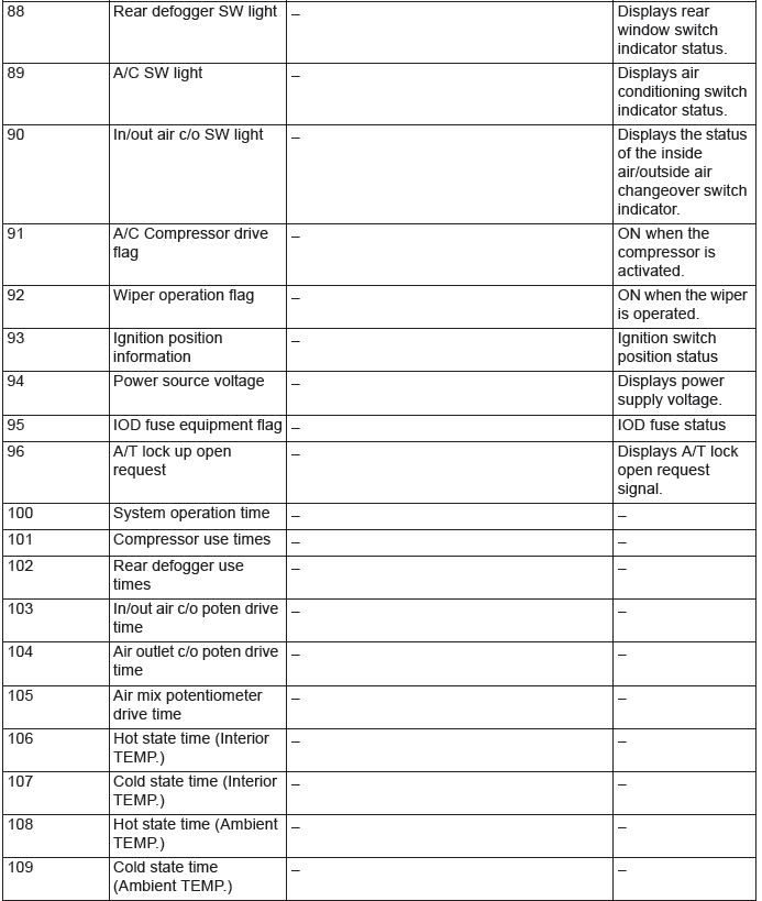
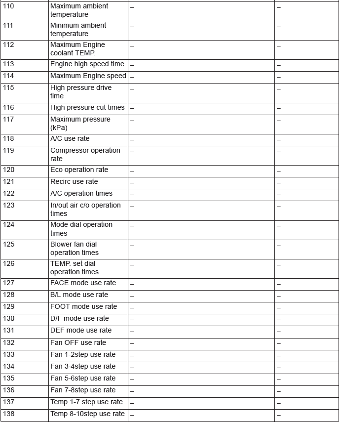
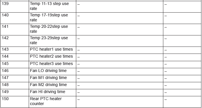
The displayed items are as shown in the table below.
DISPLAY ITEM LIST
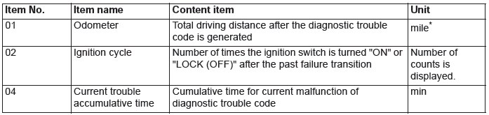
NOTE: *: If a failure occurs to both the ABS-ECU and ETACS-ECU, 0000 mile or FFFF km is displayed to the scan tool MB991958.
DIAGNOSTIC TROUBLE CODE CHART
CAUTION During diagnosis, a DTC code associated with another system may be set when the ignition switch is turned on with connector(s) disconnected.
After completing the repair, confirm all systems for DTC code(s). If DTC code(s) are set, erase them all.
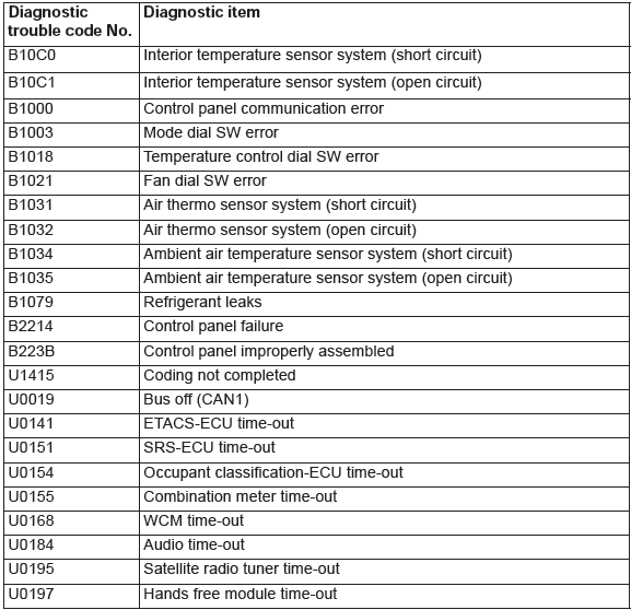
NOTE: *: This diagnostic trouble code will be set even if the system is normal.
DIAGNOSTIC TROUBLE CODE PROCEDURES
DTC B10C0, B10C1: Interior Temperature Sensor System
Interior Temperature Sensor Circuit
DTC SET CONDITION
- DTC B10C0 is set if there is a short circuit in the interior temperature sensor input circuit.
- DTC B10C1 is set if there is a defective connector connection, or if there is an open circuit in the harness.
TECHNICAL DESCRIPTION (COMMENT)
Current trouble
- The A/C-ECU, the interior temperature sensor, or connector(s) or wiring between the two may be defective.
Past trouble
If DTC B10C0 or B10C1 is stored as a past trouble, carry out diagnosis with particular emphasis on wiring and connector(s) between the A/C-ECU and the interior temperature sensor. If the connectors and wiring are normal, and obviously the ECU is the cause of the trouble, replace the ECU.
If in doubt, do not replace the ECU.
TROUBLESHOOTING HINT
- Malfunction of connector.
- Malfunction of the harness.
- Malfunction of the interior temperature sensor.
- Malfunction of the A/C-ECU.
DIAGNOSIS
Required Special Tool:
- MB991958: Scan Tool (M.U.T.-III Sub Assembly)
- MB991824: Vehicle Communication Interface (V.C.I.)
- MB991827: M.U.T.-III USB Cable
- MB991910: M.U.T.-III Main Harness A (Vehicles with CAN communication system)
STEP 1. Using scan tool MB991958, diagnose the CAN bus line.
CAUTION To prevent damage to scan tool MB991958, always turn the ignition switch to the "LOCK" (OFF) position before connecting or disconnecting scan tool MB991958.
Use scan tool MB991958 to diagnose the CAN bus lines.
(1) Connect scan tool MB991958. Refer to "How to connect the Scan Tool (M.U.T.-III)".
(2) Turn the ignition switch to "ON" position.
(3) Diagnose the CAN bus line.
Q: Is the check result satisfactory?
YES : Go to Step 2.
NO : Repair the CAN bus lines. Repair the CAN bus lines.
STEP 2. Recheck for diagnostic trouble code.
Recheck if the DTC is set.
(1) Erase the DTC.
(2) Turn the ignition switch to "ON" position.
(3) Check if the DTC is set.
Q: Is the check result satisfactory?
YES : It can be assumed that this malfunction is intermittent.
Refer to GROUP 00, How to Use Troubleshooting/Inspection Service Points − How to Cope with Intermittent Malfunctions.
NO : Go to Step 3.
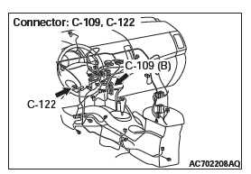
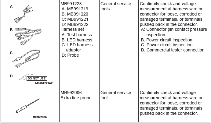
STEP 3. Check interior temperature sensor connector C-122 and A/C-ECU connector C-109 for loose, corroded or damaged terminals, or terminals pushed back in the connector.
Q: Are interior temperature sensor connector C-122 and A/C-ECU connector C-109 in good condition?
YES : Go to Step 4.
NO : Repair or replace the connector.
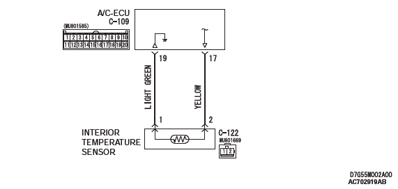
STEP 4. Check the wiring harness between A/C-ECU connector C-109 (terminals 17 and 19) and interior temperature sensor connector C-122 (terminals 2 and 1).
- Check the sensor signal line and ground line for open and short circuit.
Q: Is the wiring harness between A/C-ECU connector C-109 (terminals 17 and 19) and interior temperature sensor connector C-122 (terminals 2 and 1) in good condition?
YES : Go to Step 5.
NO : Repair the wiring harness.
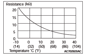
STEP 5. Check the interior temperature sensor.
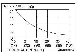
Measure the resistance between connector terminals 1 and 2 under at least two different temperatures. The resistance values should generally match those in the graph.
NOTE: The temperature at the check should not exceed the range in the graph.
Q: Is the interior temperature sensor in good condition?
YES : Replace the A/C-ECU. Then go to Step 6.
NO : Replace the interior temperature sensor. Then go to Step 6.
STEP 6. Recheck for diagnostic trouble code.
Check again if the DTC is set.
(1) Connect scan tool MB991958 to the data link connector
(2) Turn the ignition switch to the "ON" position.
(3) Check if the DTC is set.
(4) Turn the ignition switch to the "LOCK" (OFF) position.
Q: Is the check result satisfactory?
YES : The procedure is complete.
NO : Return to Step 1.
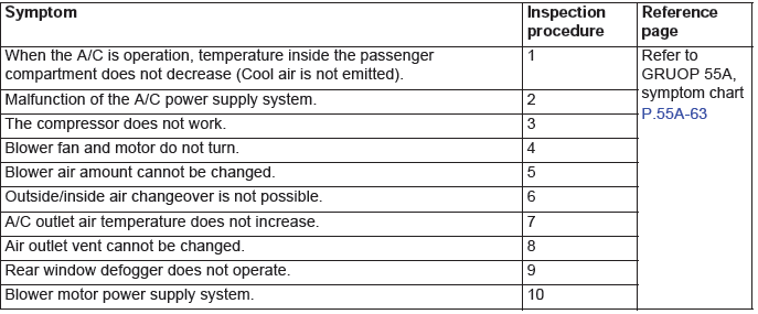
SYMPTOM CHART
CAUTION During diagnosis, a DTC code associated with another system may be set when the ignition switch is turned on with connector(s) disconnected.
On completion, confirm all systems for DTC code(s). If DTC code(s) are set, erase them all.
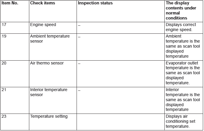
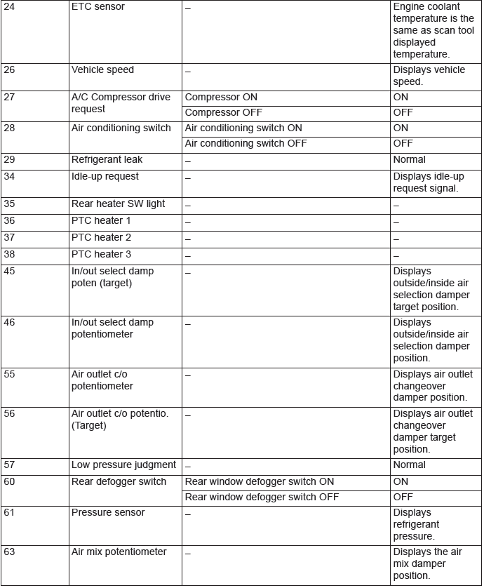
DATA LIST REFERENCE TABLE
ACTUATOR TEST REFERENCE
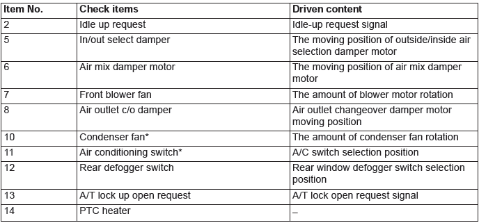
NOTE: *: When the engine is not running these function do not work.
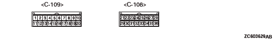
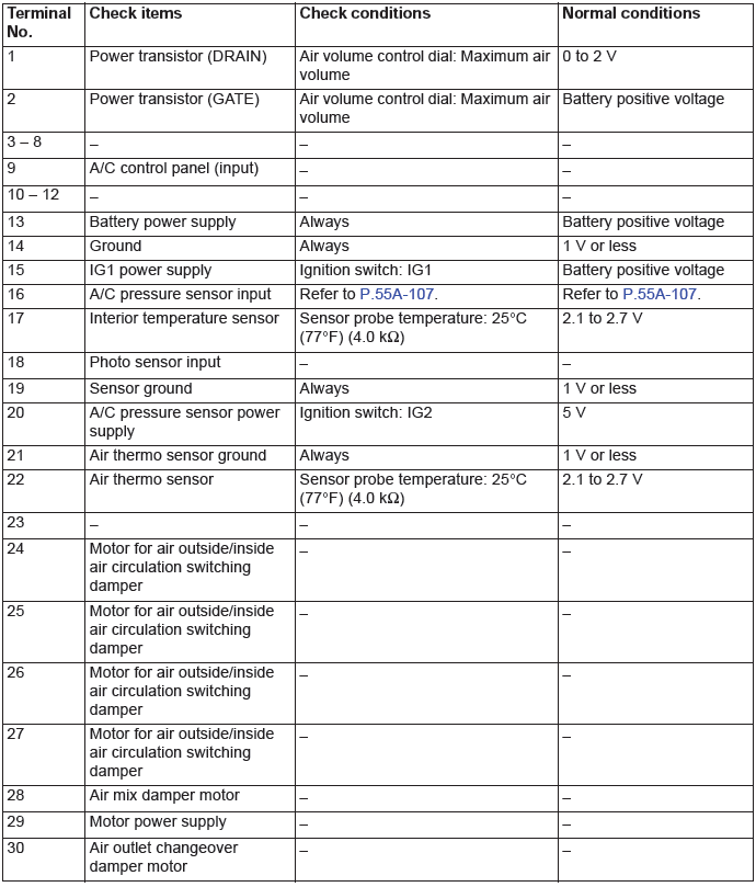
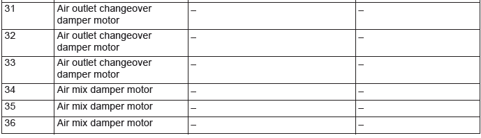
CHECK AT A/C-ECU TERMINAL
Special Tools
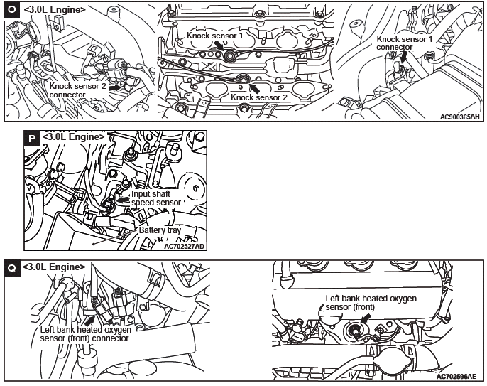
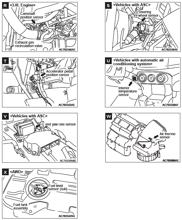
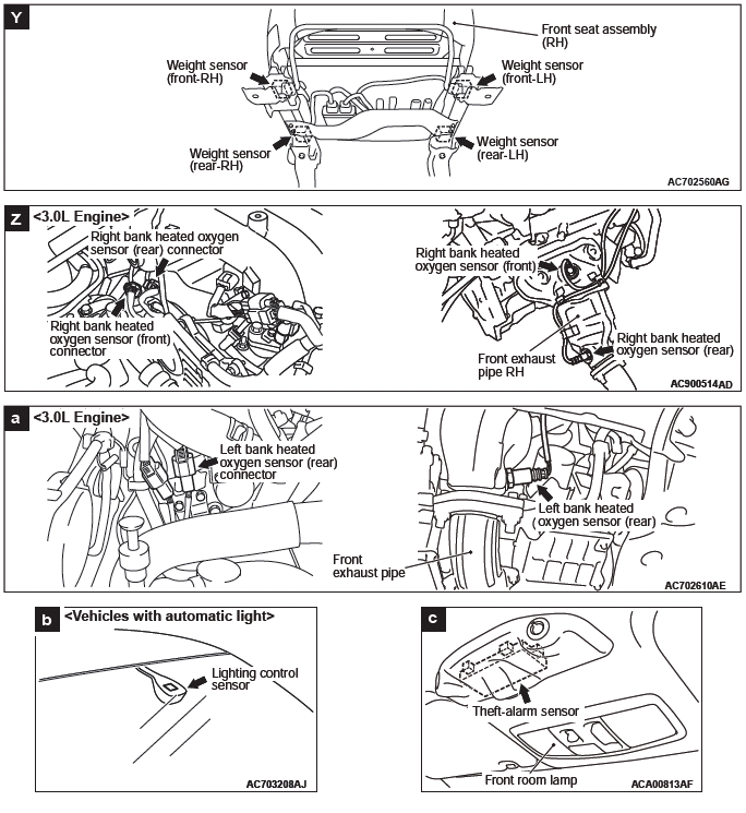
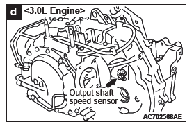
Sensors
REMOVAL AND INSTALLATION
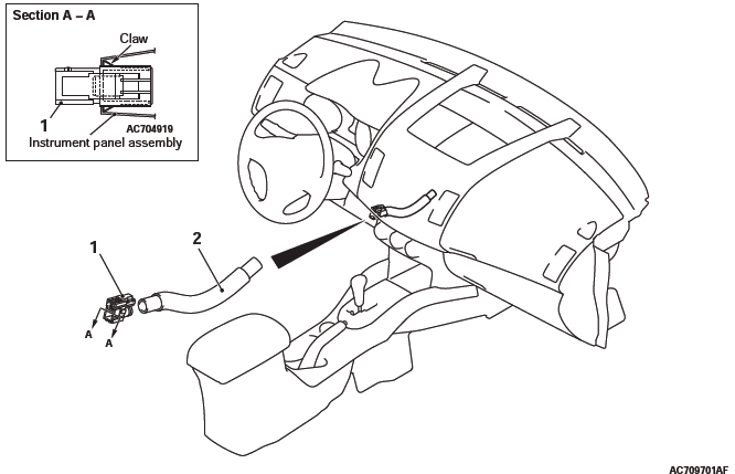
Interior temperature sensor removal steps
- Side lower panel assembly
- Interior temperature sensor
- Aspirator hose
INSPECTION
INTERIOR TEMPERATURE SENSOR CHECK
When the resistance between the sensor terminals is measured under two or more temperature conditions, the resistance should approximately satisfy the illustrated values.
NOTE: The temperature conditions when checking should not exceed the range shown in the diagram.
Other Parts
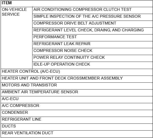
OTHER PARTS MAINTENANCE SERVICE POINTS
The following maintenance service points are the same as for the manual A/C.
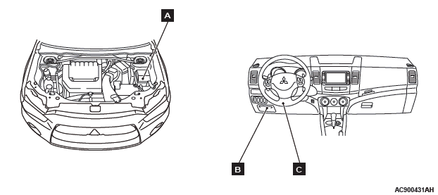
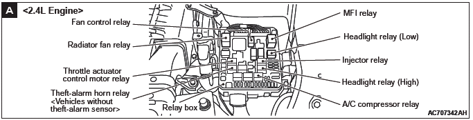
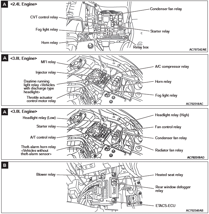
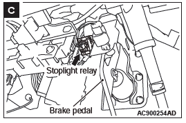
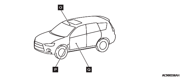
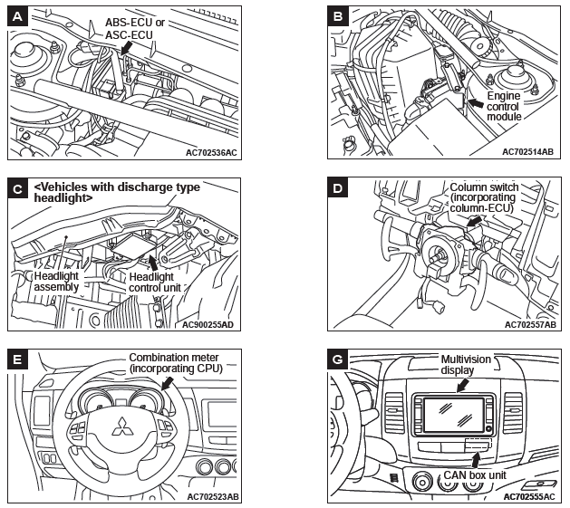
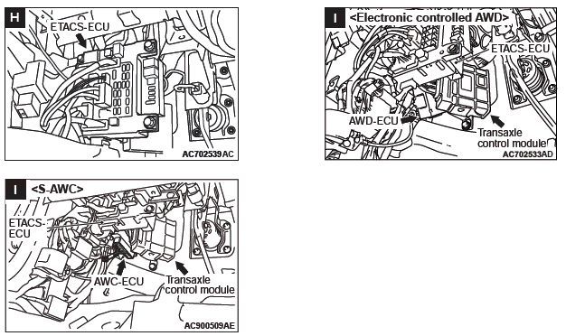
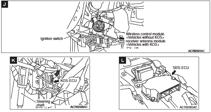
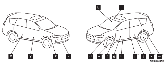
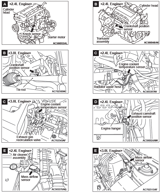
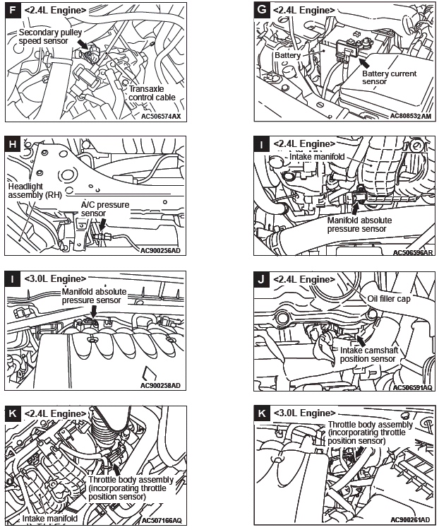
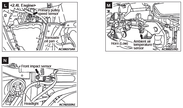
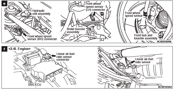
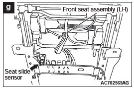
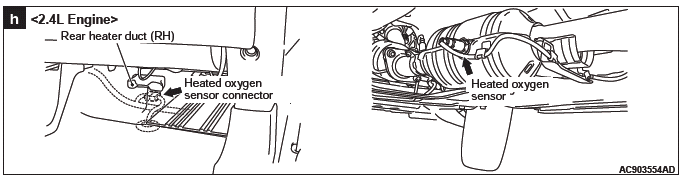
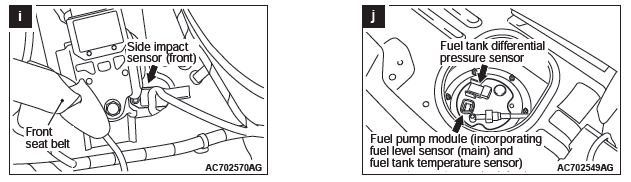
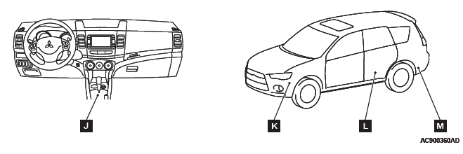
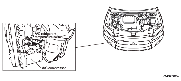
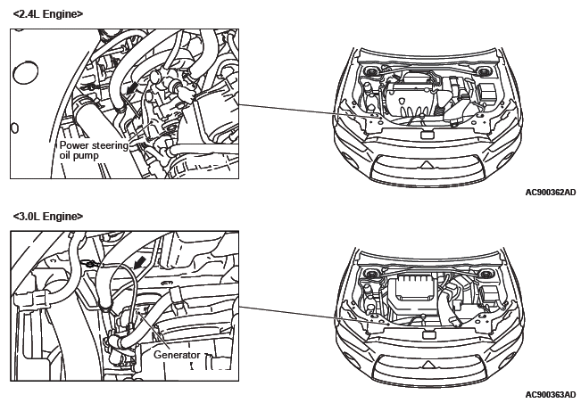
Component Locations
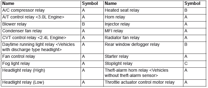
Relay
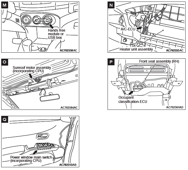
Control Unit
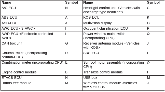
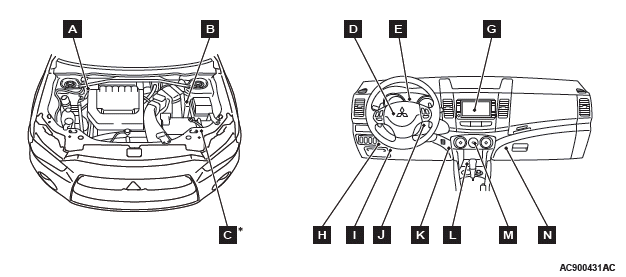
NOTE: The * symbols indicate equipment at both sides.
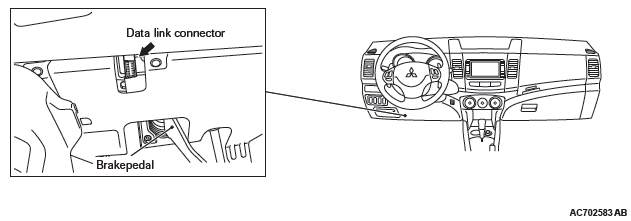
Inspection Terminal
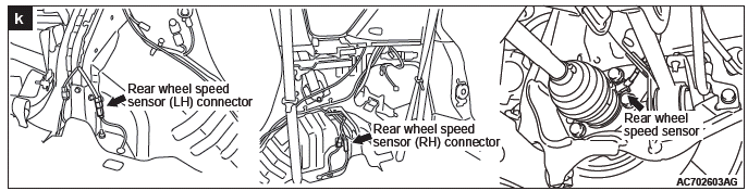
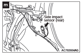
Sensor
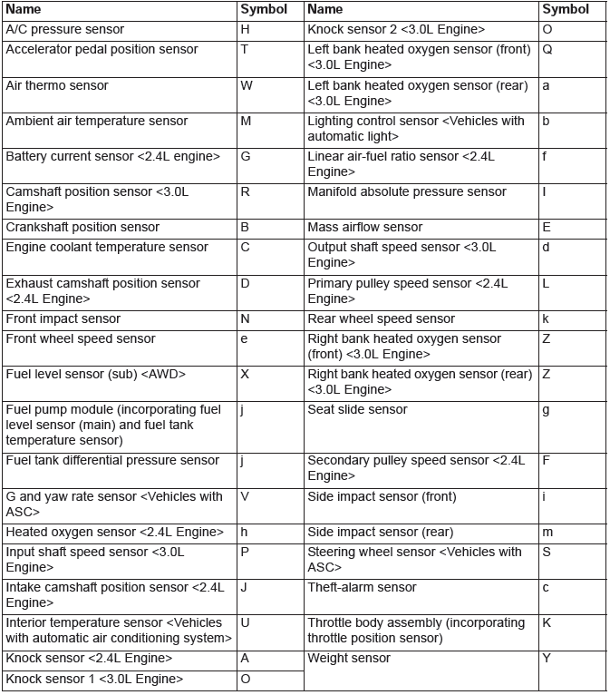
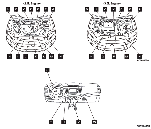
NOTE: The * symbols indicate equipment at both sides.
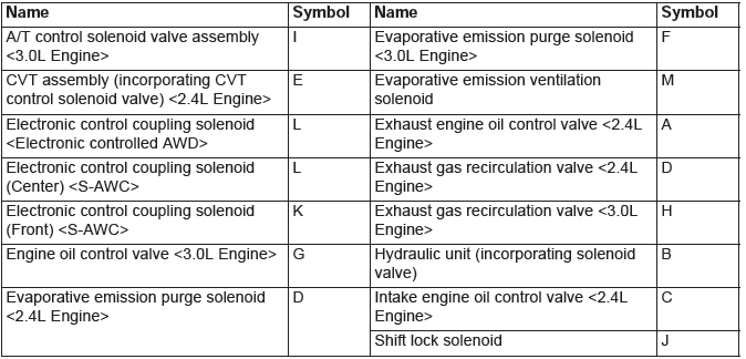
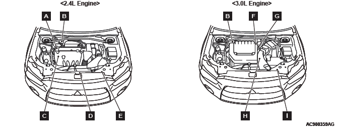
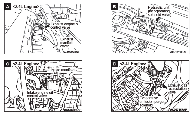
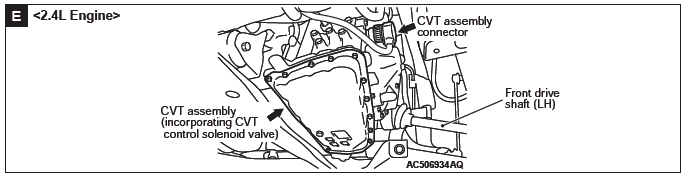
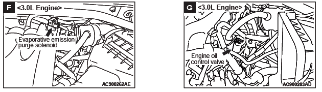
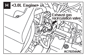
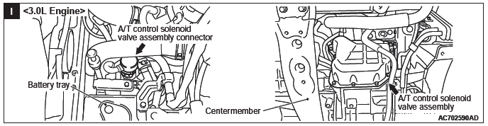
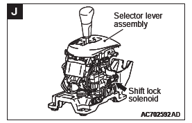
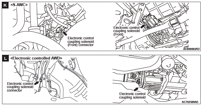
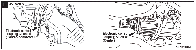
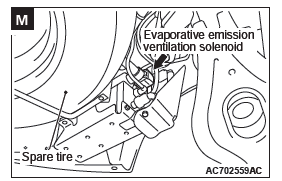
Solenoid and Solenoid Valve
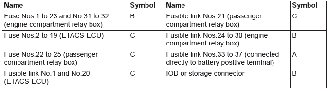
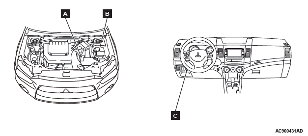
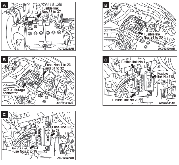
FUSIBLE LINK, FUSE AND IOD OR STORAGE CONNECTOR
Other Devices
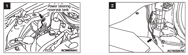
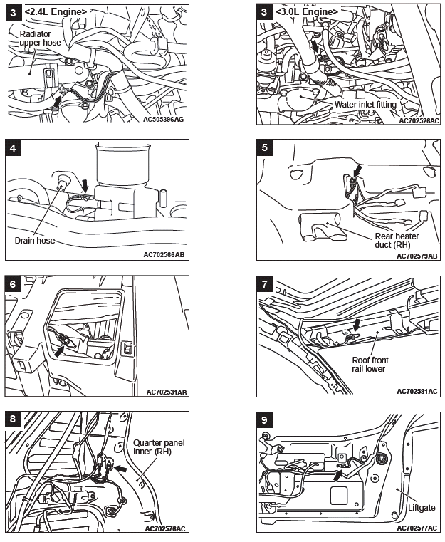
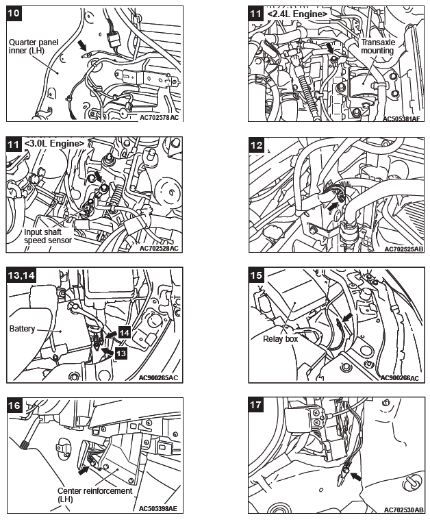
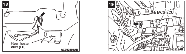
Grounding Cable
Grounding
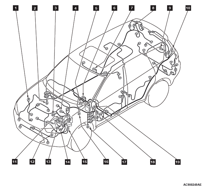
NOTE: 1 to 19 numbers correspond to the body ground point numbers in CIRCUIT DIAGRAMS.