Mitsubishi Outlander: Symptom Chart, Symptom Procedures
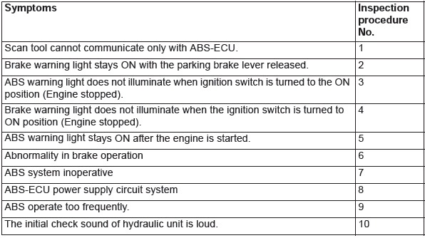
SYMPTOM CHART
CAUTION
- ABS may operate in the following conditions without hard braking: Slippery road surface, high-speed turn, and bumpy road surface. When asking the customers, confirm that they have/have not encountered ABS operation in corresponding conditions.
- During ABS operation, the brake pedal is pulled forward gradually, and noise occurs at the same time. This is because the brake line pressure varies intermittently to prevent the wheel lock, and not a system malfunction.
- During diagnosis, a diagnostic trouble code associated with other system may be set when the ignition switch is turned on with connector(s) disconnected. On completion, check all systems for diagnostic trouble code(s). If diagnostic trouble code(s) are set, erase them all.
SYMPTOM PROCEDURES
Inspection Procedure 1: Scan tool cannot communicate only with ABS-ECU.
CAUTION If there is any problem in the CAN bus lines, an incorrect diagnostic trouble code may be set. Prior to this diagnosis, diagnose the CAN bus lines (Refer to GROUP 54C − CAN Bus Line Diagnostic Flow).
TECHNICAL DESCRIPTION (COMMENT)
When scan tool cannot communicate with the ABS system, the CAN bus line, ABS-ECU power supply circuit system, or ABS-ECU may be faulty.
TROUBLESHOOTING HINTS (THE MOST LIKELY CAUSES FOR THIS CASE:)
- Damaged wiring harness and connectors
- ABS-ECU malfunction
- Wrong routing of M.U.T.-III harness
- Abnormality in battery or generator
- Abnormality in power supply voltage to ABS-ECU
- ECU malfunction of other system
DIAGNOSIS
Required Special Tools:
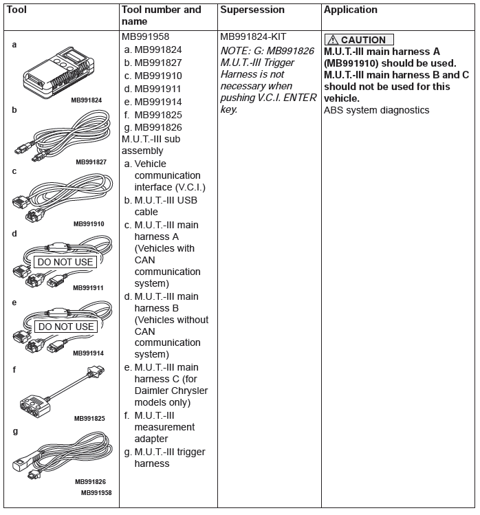
- MB991958: Scan Tool (M.U.T.-III Sub Assembly)
- MB991824: Vehicle Communication Interface (V.C.I.)
- MB991827: M.U.T.-III USB Cable
- MB991910: M.U.T.-III Main Harness A
STEP 1. Using scan tool MB991958, diagnose the CAN bus line.
Use scan tool to diagnose the CAN bus lines.
Q: Is the check result normal?
YES : Check and repair the power supply circuit system.
NO : Repair the CAN bus lines (Refer to GROUP 54C − CAN Bus Diagnostics Table).
Inspection Procedure 2: Brake warning light stays ON with the parking brake lever released.
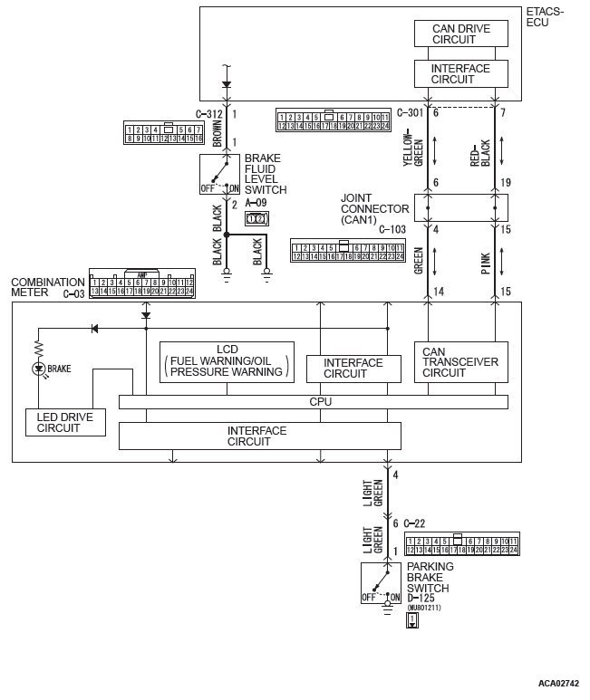
Brake Warning Light Circuit
CAUTION
- If there is any problem in the CAN bus lines, an incorrect DTC may be set. Prior to this diagnosis, diagnose the CAN bus lines (Refer to GROUP 54C − CAN Bus Line Diagnostic Flow).
- Whenever ECU is replaced, ensure that the CAN bus lines are normal.
OPERATION
- When the parking brake switch is turned ON, the combination meter terminal No. 4 is grounded, and then the brake warning light illuminates.
- When reduction of the brake fluid amount is detected, the
brake fluid level switch is turned from ON to OFF.
ETACS-ECU monitors the brake fluid level switch, and instructs the combination meter via the CAN bus line to illuminate the brake warning light.
COMMENTS ON TROUBLE SYMPTOM
This may be caused by ground fault in the parking brake switch circuit.
PROBABLE CAUSES
- The brake pad thickness is at the limit value or less.
- The brake fluid amount is at the "LOWER" level or lower.
- Poor adjustment of the parking brake lever
- Damaged wiring harness and connectors
- Parking brake switch malfunction
- Brake fluid level switch malfunction
- Combination meter malfunction
- Malfunction of ETACS-ECU
DIAGNOSIS
Required Special Tools:
- MB991958: Scan Tool (M.U.T.-III Sub Assembly)
- MB991824: Vehicle Communication Interface (V.C.I.)
- MB991827: M.U.T.-III USB Cable
- MB991910: M.U.T.-III Main Harness A
STEP 1. Using scan tool MB991958, diagnose the CAN bus line.
Use scan tool MB991958 to diagnose the CAN bus lines.
Q: Is the check result normal?
YES : Go to Step 2.
NO : Repair the CAN bus lines (Refer to GROUP 54C − CAN Bus Diagnostics Table).
STEP 2. Scan tool DTC.
Use scan tool MB991958 to check the diagnostic trouble code for the ABS system.
Q: Is the DTC set?
YES : Carry out the diagnosis for the DTC.
NO : Go to Step 3.
STEP 3. Scan tool DTC for other systems.
Use scan tool MB991958 to check that the DTC is set in the combination meter and ETACS-ECU.
Q: Is the DTC set?
YES : Carry out the diagnosis for the DTC.
NO : Go to Step 4.
STEP 4. Brake fluid level check
Check that the brake fluid is filled up to the "MIN" level or higher.
Q: Is the check result normal?
YES : Go to Step 6.
NO : Go to Step 5.
STEP 5. Brake pad check
Refer to GROUP 35A − On-vehicle Service/Brake Pad Check.
Q: Is the check result normal?
YES : Fill the brake fluid up to the "MAX" level. Then go to Step 18.
NO : Replace the brake pad (Refer to GROUP 35A − On-vehicle Service/Brake Pad Replacement). Then go to Step 18.
STEP 6. Brake fluid level switch check
Refer to GROUP 35A − On-vehicle Service/Brake Fluid Level Switch Check.
Q: Is the check result normal?
YES : Go to Step 7.
NO : Replace the reservoir tank assembly (Refer to GROUP 35A − Master Cylinder Assembly and Brake Booster Assembly). Then go to Step 18.
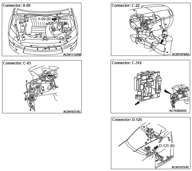
STEP 7. Connector check: A-09 brake fluid level switch connector, C-312 ETACS-ECU connector
Q: Is the check result normal?
YES : Go to Step 8.
NO : Repair the damaged connector.
STEP 8. Measure the voltage at A-09 brake fluid level switch connector.
- Disconnect the connector, and measure at the wiring harness side.
- Turn the ignition switch to the ON position.
- Measure the voltage between the terminal No.1 and the
body ground.
OK: Approximately system voltage
Q: Is the check result normal?
YES : Go to Step 10.
NO : Go to Step 9.
STEP 9. Measure the voltage at the C-312 ETACS-ECU connector.
CAUTION With the C-312 ETACS-ECU connector kept connected, disconnect the A-09 brake fluid level switch connector.
- Turn the ignition switch to the ON position.
- Measure the voltage between terminal No. 1 and the body
ground by backprobing.
OK: Approximately system voltage
Q: Is the check result normal?
YES : Check the wiring harness between the C-312 ETACS-ECU connector terminal No.1 and the A-09 brake fluid level switch connector terminal No.1.
NO : Replace the ETACS-ECU (Refer to GROUP 54A − ETACS-ECU). Then go to Step 18.
STEP 10. Wiring harness check: between A-09 brake fluid level switch connector and body ground Check for open circuit in the harness wire between A-09 brake fluid level switch connector terminal No.2 and body ground.
Q: Is the check result normal?
YES : Go to Step 11.
NO : Repair the wiring harness.
STEP 11. Parking brake lever stroke check
Q: Is the check result normal?
YES : Go to Step 12.
NO : Adjust the parking brake lever stroke (Refer to GROUP 36 − On-vehicle Service/Parking Brake Lever Stroke Check and Adjustment). Then go to Step 18.
STEP 12. Parking brake switch check
Q: Is the check result normal?
YES : Go to Step 13.
NO : Replace the parking brake switch (Refer to GROUP 36 − Parking Brake Lever). Then go to Step 18.
STEP 13. Connector check: D-125 parking brake switch connector
Q: Is the check result normal?
YES : Go to Step 14.
NO : Repair the damaged connector.
STEP 14. Measure the voltage at D-125 parking brake switch connector.
- Disconnect the connector, and measure at the wiring harness side.
- Turn the ignition switch to the "ON" position.
- Measure the voltage between the terminal No.1 and the
body ground.
OK: Approximately system voltage
Q: Is the check result normal?
YES : Go to Step 17.
NO : Go to Step 15.
STEP 15. Connector check: C-03 combination meter connector, C-22 intermediate connector
Q: Is the check result normal?
YES : Go to Step 16.
NO : Repair the damaged connector.
STEP 16. Voltage measurement with C-03 combination meter connector
- Release the parking brake lever (status that the lever is not operated).
- Turn the ignition switch to the "ON" position.
- Measure the voltage between terminal No.4 and the body
ground by backprobing without disconnecting the
connector.
OK: Approximately system voltage
Q: Is the check result normal?
YES : Repair the wiring harness between the C-03 combination meter connector terminal No.4 and the D-125 parking brake switch connector terminal No.1.
NO : Go to Step 17.
STEP 17. Retest the system.
Q: Does the brake warning light turn ON and OFF normally according to the parking brake lever operation?
YES : Intermittent malfunction (Refer to GROUP 00 − How to Use Troubleshooting/How to Cope with Intermittent Malfunctions).
NO : Replace the combination meter assembly (Refer to GROUP 54A − Combination Meter). Then go to Step 18.
STEP 18. Retest the system.
Q: Does the brake warning light turn ON and OFF normally according to the parking brake lever operation?
YES : The procedure is complete.
NO : Return to Step 1.
Inspection Procedure 3: ABS warning light does not illuminate when ignition switch is turned to the ON position (engine stopped).
CAUTION
- If there is any problem in the CAN bus lines, an incorrect DTC may be set. Prior to this diagnosis, diagnose the CAN bus lines (Refer to GROUP 54C − CAN Bus Line Diagnostic Flow).
- Whenever ECU is replaced, ensure that the CAN bus lines are normal.
SYSTEM OPERATION
- ABS-ECU sends the illumination request signal of the ABS warning light to the combination meter through ETACS-ECU via CAN communication.
- ABS-ECU illuminates the ABS warning light via ETACS-ECU for approximately 3 seconds for valve check with the ignition switch turned to the ON position.
TECHNICAL DESCRIPTION (COMMENT)
This may be caused by faults in the CAN bus line, ETACS-ECU, combination meter or ABS-ECU.
PROBABLE CAUSES
- Damaged wiring harness and connectors
- Malfunction of ETACS-ECU
- Combination meter malfunction
- ABS-ECU malfunction
- Malfunction of coding data for ETACS-ECU
DIAGNOSIS
Required Special Tools:
- MB991958: Scan Tool (M.U.T.-III Sub Assembly)
- MB991824: Vehicle Communication Interface (V.C.I.)
- MB991827: M.U.T.-III USB Cable
- MB991910: M.U.T.-III Main Harness A
STEP 1. Using scan tool MB991958, diagnose the CAN bus line.
Use scan tool to diagnose the CAN bus lines.
Q: Is the check result normal?
YES : Go to Step 2.
NO : Repair the CAN bus lines (Refer to GROUP 54C − CAN Bus Diagnostics Table). Then go to Step 9.
STEP 2. M.U.T.-III diagnostic trouble code
Use M.U.T.-III to check the diagnostic trouble code for the ABS system.
Q: Is the diagnostic trouble code set?
YES : Carry out the diagnosis for the diagnostic trouble code.
NO : Go to Step 3.
STEP 3. Scan tool actuator test
Perform the actuator test No.07 of the combination meter system, and check if the ABS warning light illuminates.
Q: Is the check result normal?
YES : Go to Step 4.
NO : Troubleshoot the combination meter, then go to Step 4.
STEP 4. Check coding data
Q: Is the check result normal?
YES : Go to Step 6.
NO : Go to Step 5.
STEP 5. ETACS-ECU variant coding
Q: Dose variant coding succeed?
YES : Go to Step 9.
NO : Replace the ETACS-ECU (Refer to GROUP 54A − ETACS-ECU), and then go to Step 9.
STEP 6. Scan tool other system diagnostic trouble code
Using scan tool, check that the diagnostic trouble code No.U0141 is not set by the combination meter system.
Q: Is the diagnostic trouble code set?
YES : Troubleshoot the combination meter, then go to Step 9.
NO : Go to Step 7.
STEP 7. Scan tool other system diagnostic trouble code
Using scan tool, check that the diagnostic trouble code No.U0121 is not set by the ETACS system.
Q: Is the diagnostic trouble code set?
YES : Troubleshoot the ETACS-ECU (Refer to GROUP 54A − ETACS/DTC), then go to Step 9.
NO : Replace the hydraulic unit (integrated with ABS-ECU), then go to Step 8.
STEP 8. Retest the system.
Q: Does the ABS warning light turn ON and OFF normally?
YES : Intermittent malfunction (Refer to GROUP 00 − How to Use Troubleshooting/How to Cope with Intermittent Malfunctions).
NO : Replace the hydraulic unit (integrated with ABS-ECU). Then go to Step 9.
STEP 9. Retest the system.
Q: Does the ABS warning light turn ON and OFF normally?
YES : The procedure is complete.
NO : Return to Step 1.
Inspection Procedure 4: Brake warning light does not illuminate when the ignition switch is turned to ON position (engine stopped).
CAUTION
- If there is any problem in the CAN bus lines, an incorrect DTC may be set. Prior to this diagnosis, diagnose the CAN bus lines (Refer to GROUP 54C − CAN Bus Line Diagnostic Flow).
- Whenever ECU is replaced, ensure that the CAN bus lines are normal.
CIRCUIT OPERATION
ABS-ECU sends the illumination request signal of the brake warning light to the combination meter through ETACS-ECU via the CAN communication.
TECHNICAL DESCRIPTION (COMMENT)
This may be caused by faults in the CAN bus line, ETACS-ECU, combination meter or ABS-ECU.
PROBABLE CAUSES
- Damaged wiring harness and connectors
- Malfunction of ETACS-ECU
- Combination meter malfunction
- ABS-ECU malfunction
DIAGNOSIS
Required Special Tools:
- MB991958: Scan Tool (M.U.T.-III Sub Assembly)
- MB991824: Vehicle Communication Interface (V.C.I.)
- MB991827: M.U.T.-III USB Cable
- MB991910: M.U.T.-III Main Harness A
STEP 1. Using scan tool MB991958, diagnose the CAN bus line.
Use scan tool to diagnose the CAN bus lines.
Q: Is the check result normal?
YES : Go to Step 2.
NO : Repair the CAN bus lines (Refer to GROUP 54C − CAN Bus Diagnostics Table).
STEP 2. Scan tool diagnostic trouble code
Use scan tool to check the diagnostic trouble code for the ABS system.
Q: Is the diagnostic trouble code set?
YES : Carry out the diagnosis for the diagnostic trouble code.
NO : Go to Step 3.
STEP 3. Scan tool other system diagnostic trouble code
Using scan tool, check that the diagnostic trouble code No.U0141 is not set by the combination meter system.
Q: Is the diagnostic trouble code set?
YES : Troubleshoot the combination meter, then go to Step 5.
NO : Go to Step 4.
STEP 4. Scan tool other system diagnostic trouble code
Using scan tool, check that the diagnostic trouble code No.U0121 is not set by the ETACS system.
Q: Is the diagnostic trouble code set?
YES : Troubleshoot the ETACS (Refer to GROUP 54A − ETACS/DTC), then go to Step 5.
NO : Replace the hydraulic unit (integrated with ABS-ECU), then go to Step 5.
STEP 5. Retest the system.
Q: Does the brake warning light turn ON and OFF normally?
YES : The procedure is complete.
NO : Return to Step 1.
Inspection Procedure 5: ABS warning light stays ON after the engine is started.
CAUTION
- If there is any problem in the CAN bus lines, an incorrect DTC may be set. Prior to this diagnosis, diagnose the CAN bus lines (Refer to GROUP 54C − CAN Bus Line Diagnostic Flow).
- Whenever ECU is replaced, ensure that the CAN bus lines are normal.
SYSTEM OPERATION
- ABS-ECU sends the illumination request signal of the ABS warning light to the combination meter through ETACS-ECU via CAN communication.
- ABS-ECU illuminates the ABS warning light via ETACS-ECU for approximately 3 seconds for valve check with the ignition switch turned to the ON position.
TECHNICAL DESCRIPTION (COMMENT)
This may be caused by faults in the CAN bus line, ETACS-ECU, combination meter or ABS-ECU.
PROBABLE CAUSES
- Damaged wiring harness and connectors
- Malfunction of ETACS-ECU
- Combination meter malfunction
- ABS-ECU malfunction
DIAGNOSIS
Required Special Tools:
- MB991958: Scan Tool (M.U.T.-III Sub Assembly)
- MB991824: Vehicle Communication Interface (V.C.I.)
- MB991827: M.U.T.-III USB Cable
- MB991910: M.U.T.-III Main Harness A
STEP 1. Using scan tool MB991958, diagnose the CAN bus line.
Use scan tool to diagnose the CAN bus lines.
Q: Is the check result normal?
YES : Go to Step 2.
NO : Repair the CAN bus lines (Refer to GROUP 54C − CAN Bus Diagnostics Table). Then go to Step 6.
STEP 2. Scan tool diagnostic trouble code
Use scan tool to check the diagnostic trouble code for the ABS system.
Q: Is the diagnostic trouble code set?
YES : Carry out the diagnosis for the diagnostic trouble code.
NO : Go to Step 3.
STEP 3. Scan tool other system diagnostic trouble code
Using scan tool, check that the diagnostic trouble code U0141 is not set by the combination meter system.
Q: Is any DTC set?
YES : Troubleshoot the combination meter (Refer to GROUP 54A − Combination Meter/DTC), then go to Step 6.
NO : Go to Step 4.
STEP 4. Scan tool other system diagnostic trouble code
Using scan tool, check that the diagnostic trouble code U0121 is not set by the ETACS system.
Q: Is any DTC set?
YES : Perform troubleshooting on ETACS-ECU (Refer to GROUP 54A − ETACS/DTC). Then go to Step 6.
NO : Go to Step 5.
STEP 5. Retest the system.
Drive the vehicle more at 6 mph (10 km/h) or high.
Q: Does the ABS warning light turn ON and OFF normally?
YES : Intermittent malfunction (Refer to GROUP 00 − How to Use Troubleshooting/How to Cope with Intermittent Malfunctions).
NO : Replace the hydraulic unit (integrated with ABS-ECU). Then go to Step 6.
STEP 6. Retest the system.
Drive the vehicle more at 6 mph (10 km/h) or high.
Q: Does the ABS warning light turn ON and OFF normally?
YES : The procedure is complete.
NO : Return to Step 1.
Inspection Procedure 6: Abnormality in brake operation
TECHNICAL DESCRIPTION (COMMENT)
- Although the cause of the trouble cannot be clearly resolved since it depends on the running status and road surface condition, the malfunction of the hydraulic circuit may occur if any diagnostic trouble code is not detected.
PROBABLE CAUSES
- Hydraulic unit (HU) malfunction
DIAGNOSIS
STEP 1. Hydraulic unit (HU) check
Q: Is the check result normal?
YES : Go to Step 2.
NO : Connect the brake tubes correctly, repair the external brake lines, or replace the hydraulic unit (integrated with ABS-ECU).
STEP 2. Retest the system.
Q: Can any fault be found with the brake operation?
YES : Check the brake system related components except ABS.
NO : The procedure is complete.
Inspection Procedure 7: ABS system inoperative.
CAUTION
If there is any problem in the CAN bus lines, an incorrect diagnostic trouble code may be set. Prior to this diagnosis, diagnose the CAN bus lines (Refer to GROUP 54C − CAN Bus Line Diagnostic Flow).
TECHNICAL DESCRIPTION (COMMENT)
In case of this trouble symptom, ABS system operation may be disabled. Diagnostic trouble code may be set by the ABS system using scan tool.
PROBABLE CAUSES
- Low battery voltage
- Wiring harness or connector failure of CAN bus line
- ABS-ECU malfunction
DIAGNOSIS
Required Special Tools:
- MB991958: Scan Tool (M.U.T.-III Sub Assembly)
- MB991824: Vehicle Communication Interface (V.C.I.)
- MB991827: M.U.T.-III USB Cable
- MB991910: M.U.T.-III Main Harness A
STEP 1. Using scan tool MB991958, diagnose the CAN bus line.
Use scan tool to diagnose the CAN bus lines.
Q: Is the check result normal?
YES : Go to Step 2.
NO : Repair the CAN bus lines (Refer to GROUP 54C − CAN Bus Diagnostics Table). On completion, go to Step 2.
STEP 2. Diagnostic trouble code check after resetting CAN bus lines
Q: Is any DTC set?
YES : Carry out the relevant troubleshooting.
NO : Go to Step 3.
STEP 3. Hydraulic unit (HU) check
Q: Is the check result normal?
YES : Go to Step 4.
NO : Repair the brake pipe or replace hydraulic unit (integrated with ABS-ECU).
STEP 4. Operation check
Q: Does ABS operate normally?
YES : The procedure is complete.
NO : Check the brake system related components except the ABS system.
Inspection Procedure 8: ABS-ECU power supply circuit system
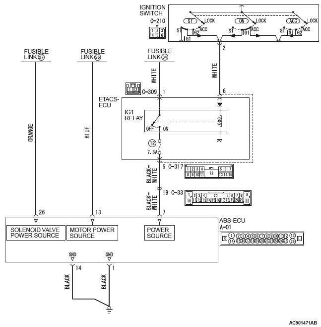
ABS-ECU Power Supply Circuit
CAUTION
- When the ABS-ECU power supply voltage becomes 9.7 +- 0.3 V or less, the ABS warning light illuminate, and the ABS control is prohibited.
- If the battery terminal is not tightened properly, a dump surge may occur and the power supply voltage may become abnormally high for a short time.
OPERATION
- ABS-ECU contains the power supply circuit (terminal No.26) for the solenoid valve. The solenoid valve is energized by the valve relay, which is incorporated in ABS-ECU.
- ABS-ECU contains the power supply circuit (terminal No.13) for the pump motor. The pump motor is energized by the motor relay, which is incorporated in ABS-ECU.
- ABS-ECU contains the power supply circuit (terminal No.7) for ABS-ECU. When the ignition switch (IG1) is turned ON, the voltage is applied to the relay incorporated in ETACS-ECU to turn ON the relay, and the power is supplied from fusible link No.34 through multi-purpose fuse No.12.
- When malfunction occurs in ABS-ECU power supply, the communication with scan tool becomes unavailable.
PROBABLE CAUSES
- Damaged wiring harness and connectors
- Malfunction of fuse and fusible link
- Improper tightening of battery terminal
- Improper tightening of ground bolt
- Battery failure
- Charging system failed
- Malfunction of ABS-ECU
DIAGNOSIS
Required Special Tools:
- MB991958 Scan Tool (M.U.T.-III Sub Assembly)
- MB991824: Vehicle Communication Interface (V.C.I.)
- MB991827 M.U.T.-III USB Cable
- MB991910 M.U.T.-III Main Harness A
- MB991974: ABS check harness
STEP 1. Battery check
Q: Is the battery in good condition?
YES : Go to Step 3.
NO : Charge or replace the battery. Then go to Step 2.
STEP 2. Charging system check
Q: Is the charging system in good condition?
YES : Go to Step 3.
NO : Repair or replace the charging system component(s).
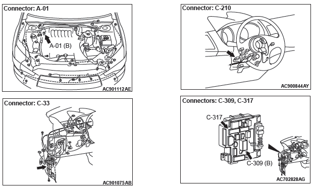
STEP 3. Connector check: A-01 ABS-ECU connector
Q: Is the check result normal?
YES : Go to Step 4.
NO : Repair the damaged connector.
STEP 4. Fusible link check: Check the fusible link No.27.
Q: Is the check result normal?
YES : Go to Step 6.
NO : Go to Step 5.
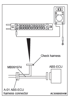
STEP 5. Resistance measurement at A-01 ABS-ECU connector
- Disconnect the ABS-ECU connector, connect special tool
ABS check harness (MB991974) to the harness-side
connector, and then measure the resistance at the special
tool connector side.
NOTE: Do not connect the special tool ABS check harness (MB991974) to ABS-ECU.
- Disconnect the fusible link No.27.
- Measure the resistance between the terminal No.26 and the
body ground.
OK: No continuity
Q: Is the check result normal?
YES : Replace the fusible link No.27. Then go to Step 27.
NO : The short circuit may be present in the power supply circuit. Repair the wiring harness between the A-01 ABS-ECU connector terminal No.26 and the fusible link No.27, and then replace the fusible link No.27.
Then go to Step 27.
STEP 6. Check the fusible link No.26.
Q: Is the check result normal?
YES : Go to Step 8.
NO : Go to Step 7.
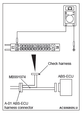
STEP 7. Resistance measurement at A-01 ABS-ECU connector
- Disconnect the ABS-ECU connector, connect special tool
ABS check harness (MB991974) to the harness-side
connector, and then measure the resistance at the special
tool connector side.
NOTE: Do not connect the special tool ABS check harness (MB991974) to ABS-ECU.
- Measure the resistance between the terminal No.13 and the
body ground.
OK: No continuity
Q: Is the check result normal?
YES : Replace the fusible link No.26. Then go to Step 27.
NO : The short circuit may be present in the power supply circuit. Repair the wiring harness between the A-01 ABS-ECU connector terminal No.13 and the fusible link No.26, and then replace the fusible link No.26.
Then go to Step 27.
STEP 8. Check the fuse No.12
Visually check for open circuit in the fuse No.12.
Q: Is the check result normal?
YES : Go to Step 11.
NO : Go to Step 9.
STEP 9. Connector check: C-33 intermediate connector, C-317 ETACS-ECU connector
Q: Is the check result normal?
YES : Go to Step 10.
NO : Repair the defective connector.
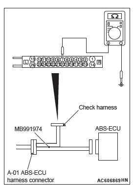
STEP 10. Resistance measurement at A-01 ABS-ECU connector
- Disconnect the C-317 ETACS-ECU connector.
- Disconnect the ABS-ECU connector, connect special tool
ABS check harness (MB991974) to the harness-side
connector, and then measure the resistance at the special
tool connector side.
NOTE: Do not connect the special tool ABS check harness (MB991974) to ABS-ECU.
- Measure the resistance between the terminal No.7 and the
body ground.
OK: No continuity
Q: Is the check result normal?
YES : Replace the fuse No.12. Then go to Step 27.
NO : The short circuit may be present in the power supply circuit. Repair the wiring harness between the A-01 ABS-ECU connector terminal No.7 and the C-317 ETACS-ECU connector terminal No.5, and then replace the fuse No.12. Then go to Step 27.
STEP 11. Fusible link check: Check the fusible link No.34.
Q: Is the check result normal?
YES : Go to Step 14.
NO : Go to Step 12.
STEP 12. Connector check: C-309 ETACS-ECU connector
Q: Is the check result normal?
YES : Go to Step 13.
NO : Repair the damaged connector.
STEP 13. Resistance measurement at C-309 ETACS-ECU connector
- Removal the fusible link No.34.
- Disconnect the C-309 ETACS-ECU connector, and then measure the resistance at the connector side.
- Measure the resistance between the terminal No.1 and the
body ground.
OK: No continuity
Q: Is the check result normal?
YES : Replace the fusible link No.34. Then go to Step 27.
NO : The short circuit may be present in the power supply circuit. Repair the wiring harness between the C-309 ETACS-ECU connector terminal No.1 and the fusible link No.34, and then replace the fusible link No.34.
Then go to Step 27.
STEP 14. Voltage measurement at the A-01 ABS-ECU connector
- Disconnect the ASC-ECU connector, connect special tool
ABS check harness (MB991974) to the harness-side
connector, and then measure the voltage at the special tool
connector side.
NOTE: Do not connect the special tool ABS check harness (MB991974) to ASC-ECU.
- Measure the voltage between terminal No.26 and body
ground.
OK: Approximately system voltage
Q: Is the check result normal?
YES : Go to Step 15.
NO : The open circuit may be present in the power supply circuit. Repair the wiring harness between the A-01 ABS-ECU connector terminal No.26 and the fusible link No.27. Then go to Step 27.
STEP 15. Voltage measurement at the A-01 ABS-ECU connector
- Disconnect the ABS-ECU connector, connect special tool
ABS check harness (MB991974) to the harness-side
connector, and then measure the voltage at the special tool
connector side.
NOTE: Do not connect the special tool ABS check harness (MB991974) to ABS-ECU.
- Measure the voltage between terminal No.13 and body
ground.
OK: Approximately system voltage
Q: Is the check result normal?
YES : Go to Step 16.
NO : The open circuit may be present in the power supply circuit. Repair the wiring harness between the A-01 ABS-ECU connector terminal No.13 and the fusible link No.26. Then go to Step 27.
STEP 16. Measure the voltage at the C-309 ETACS-ECU connector.
- Disconnect the connector, and measure at the wiring harness-side connector.
- Measure the voltage between the terminal No.1 and the
body ground.
OK: Approximately system voltage
Q: Is the check result normal?
YES : Go to Step 17.
NO : The open circuit may be present in the power supply circuit. Repair the wiring harness between the C-309 ETACS-ECU connector terminal No.1 and fusible link No.34. Then go to Step 27.
STEP 17. Connector check: C-317 ETACS-ECU connector
Q: Is the check result normal?
YES : Go to Step 18.
NO : Repair the damaged connector.
STEP 18. Measure the voltage at the C-317 ETACS-ECU connector.
- Measure by backprobing without disconnecting the connector.
- Turn the ignition switch to the "ON" position.
- Measure the voltage between the terminal No.6 and the
body ground.
OK: Approximately system voltage
Q: Is the check result normal?
YES : Go to Step 21.
NO : Go to Step 19.
STEP 19. Connector check: C-210 ignition switch connector
Q: Is the check result normal?
YES : Go to Step 20.
NO : Repair the damaged connector.
STEP 20. Check the harness wire between C-210 ignition switch connector terminal No.2 and C-317 ETACS-ECU connector terminal No.6.
- Check the communication lines for open circuit and short circuit.
Q: Is the check result normal?
YES : Troubleshooting the ignition switch (Refer to GROUP 54A − Ignition Switch/Trouble Symptom Chart).
NO : Repair the wiring harness, and then go to Step 27.
STEP 21. Measure the voltage at the C-317 ETACS-ECU connector.
- Measure at ETACS-ECU side connector.
NOTE: Do not disconnect the connector.
- Turn the ignition switch to the "ON" position.
- Measure the voltage between terminal No.5 and the body
ground by backprobing.
OK: Approximately system voltage
Q: Is the check result normal?
YES : Go to Step 23.
NO : Go to Step 22.
STEP 22. Check the harness wire between A-01 ABS-ECU connector terminal No.7 and C-317 ETACS-ECU connector terminal No.5.
- Check the harness wire for short circuit.
NOTE: Prior to the wiring harness inspection, check intermediate connector C-33, and repair if necessary.
Q: Is the check result normal?
YES : Replace the ETACS-ECU (Refer to GROUP 54A − ETACS-ECU ), and then go to Step 27.
NO : Repair the wiring harness, and then go to Step 27.
STEP 23. Connector check: C-33 intermediate connector
Q: Is the check result normal?
YES : Go to Step 24.
NO : Repair the damaged connector.
STEP 24. Voltage measurement at A-01 ABS-ECU connector
- Disconnect the ABS-ECU connector, connect special tool
ABS check harness (MB991974) to the harness-side
connector, and then measure the resistance at the special
tool connector side.
NOTE: Do not connect the special tool ABS check harness (MB991974) to ABS-ECU.
- Turn the ignition switch to the "ON" position.
- Measure the voltage between terminal No.7 and body
ground.
OK: Approximately system voltage
Q: Is the check result normal?
YES : Go to Step 25.
NO : The open circuit may be present in the power supply circuit. Repair the wiring harness between the A-01 ABS-ECU connector terminal No.7 and the C-317 ETACS-ECU connector terminal No.5. Then go to Step 27.
STEP 25. Resistance measurement at A-01 ABS-ECU connector
- Disconnect the ABS-ECU connector, connect special tool
ABS check harness (MB991974) to the harness-side
connector, and then measure the resistance at the special
tool connector side.
NOTE: Do not connect the special tool ABS check harness (MB991974) to ABS-ECU.
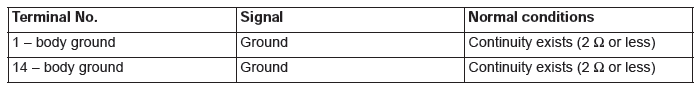
- Measure the resistance between the terminal No.1 and the body ground, and between the terminal No.14 and the body ground OK: Continuity exists (2 Ω or less)
Q: Is the check result normal?
YES : Go to Step 26.
NO : An open circuit may be present in the ground circuit.
Repair the wiring harness between the A-01 ASC-ECU connector terminal No.1 and the body ground, and between the A-01 ASC-ECU connector terminal No.14 and the body ground. Then go to Step 27.
STEP 26. Retest the system.
Make sure that the M.U.T.-III cable is properly connected and the V.C.I. switch is ON, Q: Is the communication with scan tool possible?
YES : Intermittent malfunction (Refer to GROUP 00 − How to Use Troubleshooting/How to Cope with Intermittent Malfunctions).
NO : Replace the hydraulic unit (integrated with ABS-ECU). Then go to Step 27.
STEP 27. Retest the system.
Q: Is the communication with scan tool possible?
YES : Return to Step 1.
NO : The procedure is complete.
Inspection Procedure 9: ABS operates too frequently.
CAUTION If there is any problem in the CAN bus lines, an incorrect diagnostic trouble code may be set. Prior to this diagnosis, diagnose the CAN bus lines (Refer to GROUP 54C − CAN Bus Line Diagnostic Flow).
COMMENTS ON TROUBLE SYMPTOM
- Although the cause of the trouble cannot be clearly resolved since it depends on the running status and road surface condition, the malfunction of the hydraulic circuit may occur if any DTC is not detected.
- If wheels and tires other than the ones with genuine specified size are mounted, the ABS may be activated prematurely.
- If a non-genuine braking device or non-genuine impact reduction device is mounted, the ABS may be activated prematurely.
PROBABLE CAUSES
- Mounting of wheels and tires other than with genuine specified size
- Tire pressure abnormality
- Tire wear and deterioration
- Mounting of non-genuine braking device or impact reduction device
- Wheel alignment abnormality
- Malfunction of brake related parts
- ABS-ECU malfunction
- Malfunction of hydraulic circuit
- External radio wave noise interference
DIAGNOSIS
Required Special Tools:
- MB991958: Scan Tool (M.U.T.-III Sub Assembly)
- MB991824: Vehicle Communication Interface (V.C.I.)
- MB991827 M.U.T.-III USB Cable
- MB991910 M.U.T.-III Main Harness A
STEP 1. Check the wheels and the tires.
Carry out the following check.
- Size check of wheels and tires
- Tire wear and deterioration statuses
- Check the tire pressure.
NOTE: For the tire pressure, refer to the tire pressure label attached to the lower section of driver's side door striker.
Q: Is the check result normal?
YES : Go to Step 2.
NO : Correct the wheels and tires in good condition. Then go to Step 9.
STEP 2. DTC check
Use scan tool MB991958 to check the DTC for the ABS system.
Q: Is the check result normal?
YES : Go to Step 3.
NO : Carry out the diagnosis for the DTC. Then go to Step 9.
STEP 3. Check of brake system related components other than hydraulic unit (integrated with ABS-ECU)
At the same time with the following checks, also check that no parts other than the genuine parts are mounted.
- Brake pad check
- Brake disk run-out check
- Brake drag force check
Q: Is the check result normal?
YES : Go to Step 4.
NO : Repair or replace the part(s) having damage or other problems. Then go to Step 9.
STEP 4. Wheel alignment check
At the same time with the following checks, also check that no parts other than the genuine parts are mounted.
- Front wheel alignment check (Refer to GROUP 33 − On-vehicle Service/Front Wheel Alignment Check and Adjustment)
- Rear wheel alignment check (Refer to GROUP 34 − On-vehicle Service/Rear Wheel Alignment Check and Adjustment.)
Q: Is the check result normal?
YES : Go to Step 5.
NO : Repair or replace the part(s) having damage or other problems. Then go to Step 9.
STEP 5. Scan tool data list
Check the following data list.
- Item No. 01: FL wheel speed sensor
- Item No.02: FR wheel speed sensor
- Item No.03: RL wheel speed sensor
- Item No.04: RR wheel speed sensor
Q: Is the check result normal?
YES : Go to Step 7.
NO : Go to Step 6.
STEP 6. Wheel speed sensor check
Check that no non-genuine electronic device or no wiring harness of other than genuine electronic device is mounted near the wheel speed sensor (at wheel speed detection section and wiring harness section).
Q: Is the check result normal?
YES : Go to Step 7.
NO : Remove the non-genuine electronic device or the wiring harness of non-genuine electronic device.
Then go to Step 9.
STEP 7. Hydraulic unit check
Carry out the following actuator tests, and check if they work normally.
- Item No. 01: FL wheel ABS
- Item No.02: FR wheel ABS
- Item No.03: RL wheel ABS
- Item No.04: RR wheel ABS
Q: Is the check result normal?
YES : Go to Step 8.
NO : Replace the hydraulic unit (integrated with ABS-ECU). Then go to Step 9.
STEP 8. ABS operation check
Q: Is the check result normal?
YES : Intermittent malfunction (Refer to GROUP 00 − How to Use Troubleshooting/How to Cope with Intermittent Malfunctions).
NO : Replace the hydraulic unit (integrated with ABS-ECU). Then go to Step 9.
STEP 9. ABS operation check
Q: Is the check result normal?
YES : This diagnosis is complete.
NO : Return to Step 1.
Inspection Procedure 10: The initial check sound of hydraulic unit is loud.
CAUTION When installing brake tube, match the axial center of flare nut and brake tube with the center of hole at the hydraulic unit side, and check that the fluid does not leak.
COMMENT ON TROUBLE SYMPTOM
The operation sound may be decreased by reducing the load at the rubber mount portion of the brake tube and hydraulic unit.
PROBABLE CAUSES
- Improper installation of the hydraulic unit
- Improper installation of the brake tube
DIAGNOSIS
DRIVING CHECK
- Turn the ignition switch from the "LOCK" (OFF) position to the "ON" position.
- When vehicle speed reaches 6 mph (10 km/h), check the
operating sound volume and compare it with that of the
same model.
OK: The operating sound is the same volume or less by comparing with that of the same model.
Q: Is the check result normal?
YES : This diagnosis is complete.
NO : Carry out adjustment for hydraulic unit installation.
DATA LIST REFERENCE TABLE
The following items can be read by the scan tool from the ABS-ECU input data.
The following items of ECU input data can be read using scan tool.
1. The system is normal.
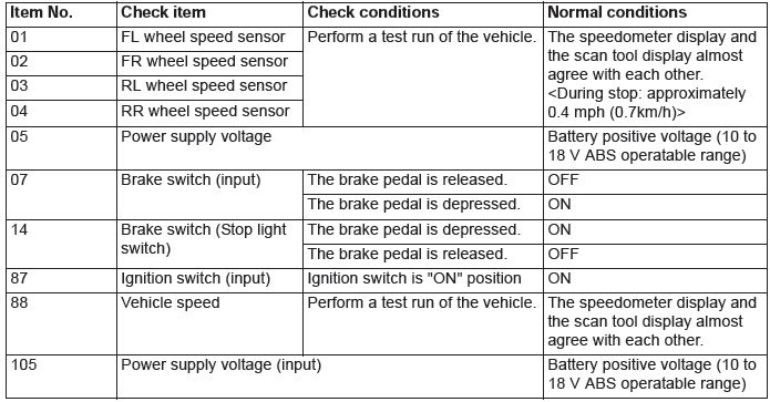
2. System shutdown by ECU
While ABS-ECU is disabled by the diagnostic function, the scan tool displayed data is different from the actual measurement.
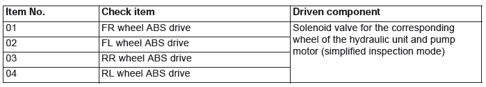
ACTUATOR TEST REFERENCE TABLE
Using scan tool, the following actuators can be forcibly operated:
NOTE:
- ABS is operated by ABS-ECU.
- When ABS-ECU is disabled due to the fail-safe function, the actuator test cannot be performed.
- The actuator test can be performed only when the vehicle is stationary.
- While the actuator test is performed, the ABS warning light flashes at a rate of 2 Hz.
- After the actuator test has been performed, the brake warning light and ABS warning light illuminate until the ignition switch is turned to ON again or the communication between scan tool and ABS-ECU is terminated.
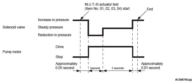
Actuator test specifications
Operation pattern of items 01 to 04
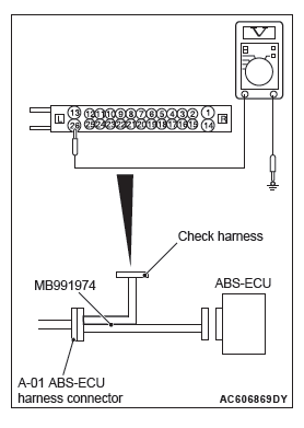
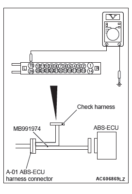
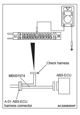
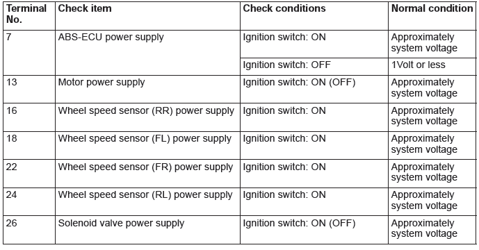
CHECK AT ECU TERMINALS
TERMINAL VOLTAGE CHECK
Required Special Tool:
MB991974: ABS Check Harness
Connect the special tool ABS check harness (MB991974) to measure the voltage between each check connector terminal and the ground terminal (No.1 or 14).
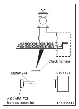
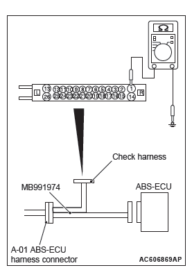
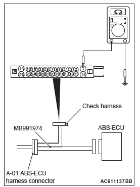
RESISTANCE AND CONTINUITY BETWEEN HARNESS-SIDE CONNECTOR TERMINALS
Required Special Tool:
MB991974: ABS Check Harness
1. When performing the continuity check, turn the ignition switch to LOCK (OFF) position, connect the special tool ABS check harness (MB991974) as shown in the figure, and disconnect the ABS-ECU connector.
2. Check for continuity between terminals shown in the chart below.
3. Terminal layout is shown in the figure.
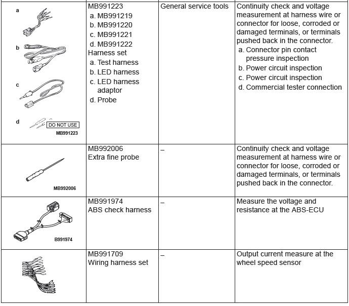
Special Tools
READ NEXT:
 On-vehicle Service
WHEEL SPEED SENSOR OUTPUT CURRENT
MEASUREMENT
Required Special Tools:
MB991709: Wiring harness set
The relevant wheel, on which the wheel speed sensor is fitted,
should be free to run.
1. Remove t
Wheel Speed Sensor
REMOVAL AND INSTALLATION
CAUTION
The vehicle speed detection encoder collects any
metallic particle easily, because it is magnetized.
Make sure that the encoder should not collect
any metallic partic
Active Stability Control System (ASC)
Service Specifications
Diagnosis
INTRODUCTION TO ASC DIAGNOSIS
The active stability control system (ASC) operates
differently from conventional brake systems. These
differences include sounds, sensat
SEE MORE:
Balancer Timing Chain, Balancer Shaft and Oil Pump Module
REMOVAL AND INSTALLATION
Pre-removal and Post-installation Operation
Timing Chain Removal and Installation
Removal steps
Timing chain tensioner
Balancer timing chain guide
Balancer timing chain guide
Balancer shaft and oil pump
module
Balancer timing chain
Crankshaft sprocket
Required S
Brake fluid/Clutch fluid
The brake fluid and the clutch fluid share reservoir tank.
To check the fluid level
The fluid level must be between the “MAX” and “MIN” marks on the reservoir.
The fluid level is monitored by a float. When the fluid level falls below the
“MIN” mark, the brake fluid warning lamp li
