Mitsubishi Outlander: Instrument Panel Assembly
Adhesive

NOTE: The symbol in parentheses indicates a part number.
Special Tool
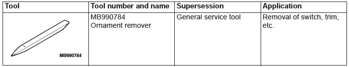
Instrument Panel Assembly
REMOVAL AND INSTALLATION
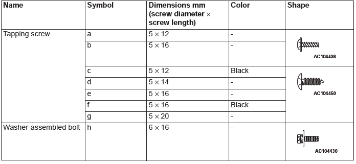
The following bolts and screws are used for installing the instrument panel: The bolts and screws are indicated by symbols in the illustrations in sections "REMOVAL AND INSTALLATION" and "DISASSEMBLY AND ASSEMBLY".
CAUTION
- For the removal of the front passenger's air bag module, refer to GROUP 52B − Service Precautions, Driver's and Front Passenger's Air Bag Module, and Clock Spring before operation.
- Do not subject SRS-ECU to any shocks when removing or installing the instrument panel.
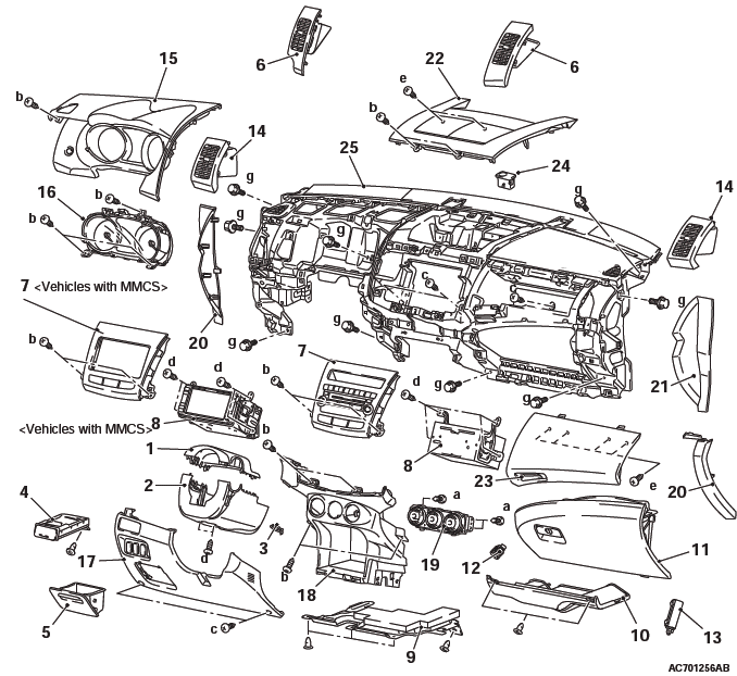
Removal steps
- Steering column upper cover
- Steering column lower cover
- Ignition key cover
- Cup holder assembly
- Side box
- Center air outlet
- Center panel assembly
- Multivision display <Vehicles with MMCS> or Radio and CD player <Vehicles without MMCS>
- Bottom cover assembly (driver's seat)
- Bottom cover assembly (front passenger's seat)
- Glove box lamp connector
- Glove box assembly
- Glove box lock cylinder
- Glove box damper
- Side air outlet
- Combination meter bezel
- Combination meter assembly
- Side lower panel assembly
- Lower side cover
- Center lower panel
- A/C control panel
- Side cover
- Glove box side panel
- Center upper panel
- Upper glove box assembly
- Steering wheel
- Solar sensor
- Instrument panel assembly
CLIP AND CLAW POSITIONS
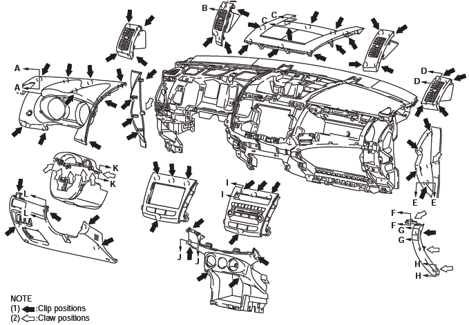
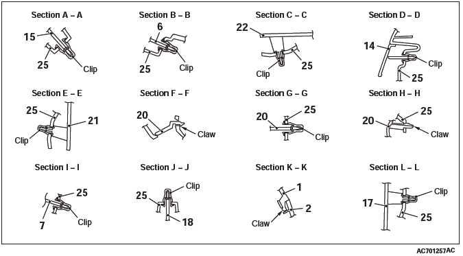
NOTE: Each number in the illustration indicates a part number.
REMOVAL SERVICE POINTS
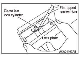
GLOVE BOX LOCK CYLINDER REMOVAL
While pulling the lever as shown in the figure, press in the lock plate of the glove box lock cylinder (brass-colored portion) using a flat-tipped screwdriver and push out the glove box lock cylinder to the direction of the arrow.
NOTE: Always unlock the glove box lock cylinder before removal because the glove box lock cylinder cannot be removed when it is locked.
INSTALLATION SERVICE POINT
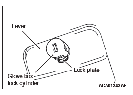
GLOVE BOX LOCK CYLINDER INSTALLATION
1. Set the glove box lock cylinder in the direction shown in the figure, and insert the lock plate to the installation hole of the lever.
2. Press in the glove box lock cylinder.
DISASSEMBLY AND ASSEMBLY
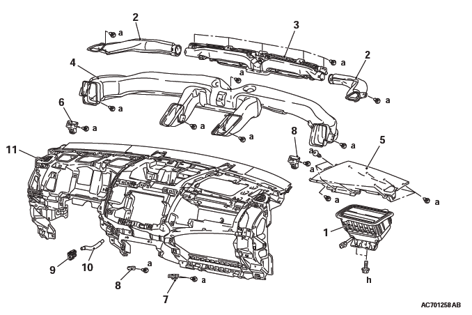
Disassembly steps
- Front passenger's seat air bag module
- Side defroster nozzle
- Center defroster nozzle
- Ventilation air distribution
- Front passenger's air bag lid assembly
- Instrument holder
- Glove box light bracket
- Wiring harness bracket
- Interior temperature sensor
- Aspirator hose
- Instrument panel
READ NEXT:
 Floor Console Assembly
FRONT FLOOR CONSOLE ASSEMBLY
REMOVAL AND INSTALLATION
Removal steps
Lower side cover
Front floor console bracket
Front floor console panel
Rear floor console assembly
Front floor console as
Trims
INTERIOR TRIM
REMOVAL AND INSTALLATION
Removal steps
Front scuff plate
Cowl side trim
Rear scuff plate
Front door opening trim
Rear door opening trim
Front pillar trim
Garnish clip
Center pi
Seat Assembly
FRONT SEAT ASSEMBLY
REMOVAL AND INSTALLATION
CAUTION
To remove the front seat assembly of vehicle with side air bag, refer to
GROUP 52B - Service Precautions and Curtain Air Bag Module.
Removal step
SEE MORE:
Inside tailgate release
The inside tailgate release is designed to provide a way to open the tailgate
in the case of a discharged battery.
The tailgate release lever (see illustration) is mounted on the tailgate.
You and your family should familiarise yourselves with the location and operation
of the tailgate relea
Exhaust Manifold
REMOVAL AND INSTALLATION
<4WD>
Removal steps
Exhaust manifold bracket C
Exhaust manifold bracket A
Crankshaft position sensor cover
Crankshaft position sensor
O-ring
Exhaust manifold upper cover
Exhaust manifold lower cover
Exhaust manifold
Exhaust manifold gasket
<2WD - Except
