Mitsubishi Outlander: Floor Console Assembly
Mitsubishi Outlander 2007-2013 Service Manual / Body, Exterior, Interior and Supplemental / Interior / Floor Console Assembly
FRONT FLOOR CONSOLE ASSEMBLY
REMOVAL AND INSTALLATION
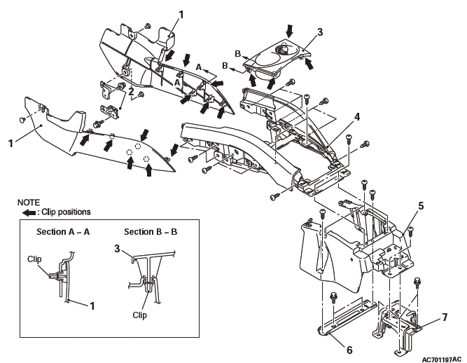
Removal steps
- Lower side cover
- Front floor console bracket
- Front floor console panel
- Rear floor console assembly
- Front floor console assembly
- Interior transmission antenna
- Front floor console base
- Front floor console base bracket
- Front floor console mid bracket
REAR FLOOR CONSOLE ASSEMBLY
REMOVAL AND INSTALLATION
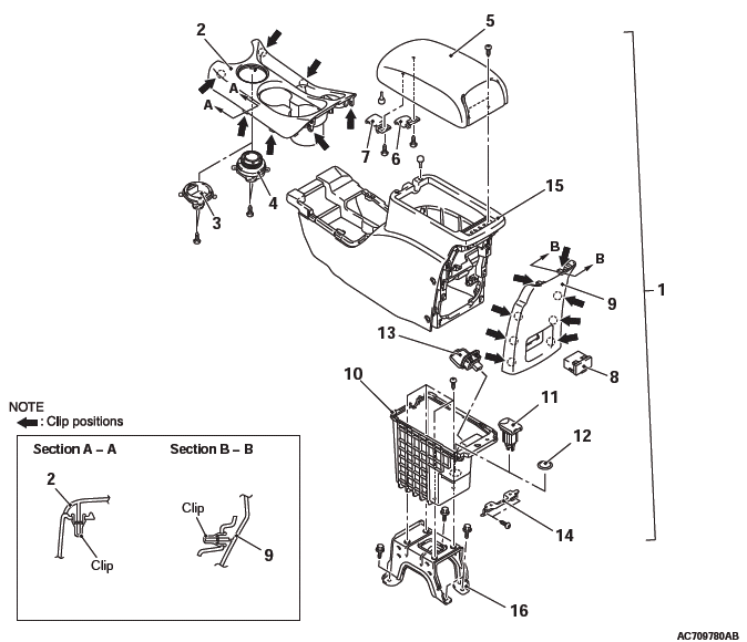
Removal steps
- Rear floor console assembly
- AWD selector switch connector
- Rear floor console front panel assembly
- Floor console plug <FWD>
- Drive mode selector <AWD>
- Armrest assembly
- Armrest box lever
- Rear floor console box lever
- VTR adapter assembly
- Rear floor console rear panel
- Rear floor console box
- USB adapter
- Accessory socket
- Cigar lighter plug
- AC inverter socket
- Rear floor console box bracket
- Accessory socket connector
- VTR adapter connector
- Rear floor console
- Rear floor console bracket
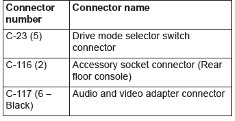
REMOVAL SERVICE POINT
WIRING HARNESS CONNECTOR DISCONNECTION
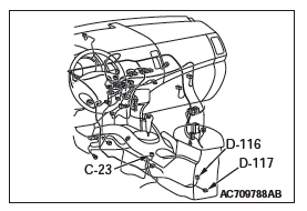
Disconnect the following wiring harness connectors:
READ NEXT:
 Trims
Trims
INTERIOR TRIM
REMOVAL AND INSTALLATION
Removal steps
Front scuff plate
Cowl side trim
Rear scuff plate
Front door opening trim
Rear door opening trim
Front pillar trim
Garnish clip
Center pi
Seat Assembly
FRONT SEAT ASSEMBLY
REMOVAL AND INSTALLATION
CAUTION
To remove the front seat assembly of vehicle with side air bag, refer to
GROUP 52B - Service Precautions and Curtain Air Bag Module.
Removal step
SEE MORE:
Control Link, Upper Arm and Lower Arm
REMOVAL AND INSTALLATION
CAUTION
The parts indicated by *1 should be temporarily tightened, and then
fully tightened with the vehicle
standing on the ground and the curb weight condition.
The parts indicated by *2 are the bolts/nuts with friction
coefficient stabilizer. In removal, ensure
Door Assembly, Door Glass and Regulator, Door Handle and Latch
Door Assembly
REMOVAL AND INSTALLATION
Post-installation operation
Door adjustment
<Front door>
Damper removal
Damper
Door assembly and front door
hinge removal steps
Front scuff plate, cowl side trim
Wiring harness connector
connection
Door check connecting bolt
Door assembly
© 2010-2026 Copyright www.mioutlander.com
