Mitsubishi Outlander: Trims
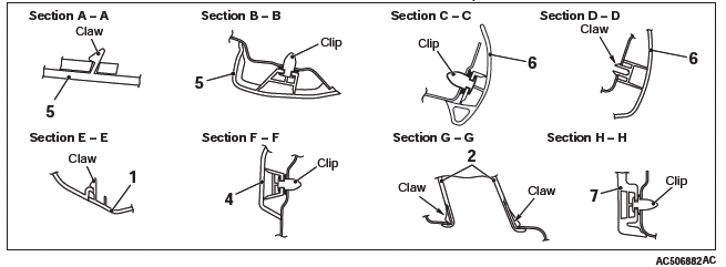
INTERIOR TRIM
REMOVAL AND INSTALLATION
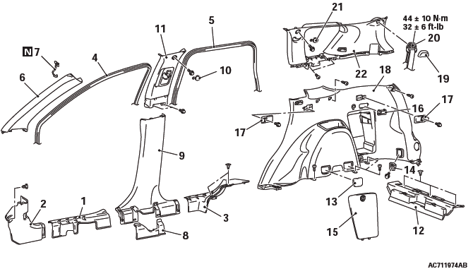
Removal steps
- Front scuff plate
- Cowl side trim
- Rear scuff plate
- Front door opening trim
- Rear door opening trim
- Front pillar trim
- Garnish clip
- Center pillar trim lower cover
- Seat belt pre-tensioner connector
- Center pillar trim, lower
- Center pillar trim upper cap
- Center pillar trim, upper
- Rear end trim
Quarter trim lower and quarter trim upper removal steps
- Maintenance lid
- Cargo hook assembly
- Jack lid assembly
- Tumble switch
- Utility bar plug
- Quarter trim, lower
- Third seat belt sash guide cover
- Third seat belt mounting bolt
- Quarter trim upper cap
- Quarter trim, upper
REMOVAL SERVICE POINT
FRONT PILLAR TRIM REMOVAL
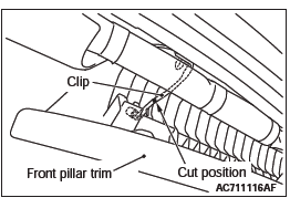
1. Pull down the front pillar trim as shown in the figure.
2. Cut the clip at the cutting position shown in the figure, taking care not to damage the other components.
3. Remove the clip remaining on the front pillar trim, taking care not to scratch the trim.
4. Remove the clip remaining on the vehicle side by breaking it to prevent damage to the flange of the clip mounting hole.
DOOR TRIM
REMOVAL AND INSTALLATION
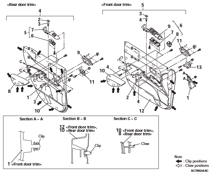
Front door trim removal steps
- Tweeter connector
- Front door sash trim
- Inside handle cover cap
- Door trim cap
- Front door trim mounting screw
- Power window switch connector, Remote-controlled mirror switch connector (RH)
- Front door trim assembly
- Power window switch panel assembly
- Power window switch
- Remote-controlled mirror switch (RH)
- Power window switch panel
- Front door armrest
- Inside handle cover
- Front door trim
- Front door pull handle bracket
Rear door trim removal steps
- Inside handle cover cap
- Door trim cap
- Rear door trim mounting screw
- Rear power window sub-switch connector
- Rear door trim assembly
- Power window switch panel assembly
- Power window switch
- Power window switch panel
- Rear door armrest
- Inside handle cover
- Rear door trim
- Rear door armrest bracket
REMOVAL SERVICE POINTS
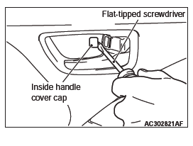
INSIDE HANDLE COVER CAP REMOVAL
Insert a flat-tipped (−) screwdriver as shown in the figure to remove the inside handle cover cap.
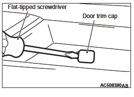
DOOR TRIM CAP REMOVAL
Insert a flat-tipped (−) screwdriver as shown in the figure to remove the door trim cap.
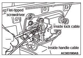
FRONT/REAR DOOR TRIM REMOVAL
Using a flat-tipped (−) screwdriver as shown in the figure, remove the inside lock cable and the inside handle cable, then remove the door trim.
INSTALLATION SERVICE POINTS
POWER WINDOW SWITCH INSTALLATION
After the power window switch is installed or replaced, perform learning of the power window fully-closed position.
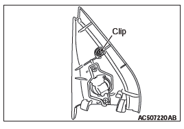
FRONT DOOR SASH TRIM INSTALLATION
Install it with the clip attached as shown in the figure.
LIFTGATE TRIM
REMOVAL AND INSTALLATION
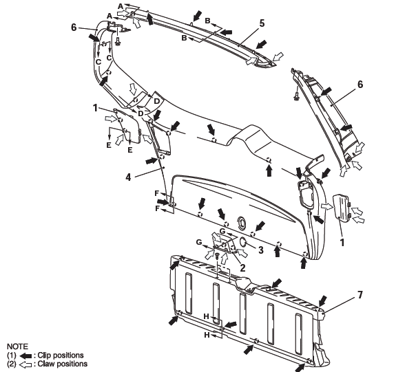
Removal steps
- Liftgate cover garnish
- Liftgate pull handle
- Liftgate trim cap
- Liftgate trim
- Liftgate upper trim
- Liftgate opening side trim
- Lower liftgate trim
Headlining
REMOVAL AND INSTALLATION
CAUTION For the removal of the headlining, refer to GROUP 52B − Service Precautions and Curtain Air Bag Module.
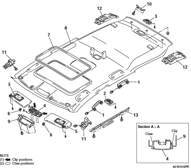
Removal steps
- Quarter trim upper, center pillar trim upper, and front pillar trim
- Rear display
- Assist grip
- Rear dome light assembly
- Cargo dome light assembly
- Front dome light connector
- Sunroof switch connector <vehicles with sunroof>
- Front dome light assembly
- Sun visor
- Sun visor holder
- Sunroof lid inner weather strip rear <vehicles with sunroof>
- Headlining
- Front dome light bracket
- Luggage compartment light bracket
- Front energy absorber roof side box
- Rear energy absorber roof side box <vehicles without curtain air bag>
- Front energy absorber roof bracket <vehicles wit sunroof>
REMOVAL SERVICE POINTS
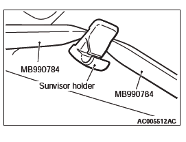
SUN VISOR HOLDER REMOVAL
Insert the special tools into the sun visor holder from its left and right sides to disengage the claws on the sun visor holder sides.
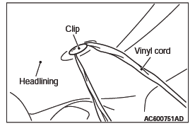
HEADLINING ASSEMBLY REMOVAL
To remove the clip, insert a vinyl cord into a clearance between the clip and the headlining, and pass it around the clip. Then, pull out the clip downwards while pulling the vinyl cord.
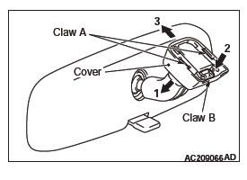
Interior Mirror
REMOVAL SERVICE POINT
1. Disengage the claw A and lower the cover toward arrow 1 direction.
2. Push the claw B toward arrow 2 direction to unlock, and pull out the mirror toward arrow 3 direction.
READ NEXT:
 Seat Assembly
FRONT SEAT ASSEMBLY
REMOVAL AND INSTALLATION
CAUTION
To remove the front seat assembly of vehicle with side air bag, refer to
GROUP 52B - Service Precautions and Curtain Air Bag Module.
Removal step
Specifications, General Information, Service Precautions
Fastener Tightening Specifications
General Information
DANGER
The SRS-ECU adopts the rollover specification
that the curtain airbag and seat belt
pre-tensioner operate at the occurrence of
rollover.
SEE MORE:
Rear Suspension Diagnosis
INTRODUCTION TO REAR SUSPENSION DIAGNOSIS
If the rear suspension is faulty, the vehicle will not run
straightforward or noise will occur. Incorrect wheel
alignment, malfunction of shock absorber, stabilizer
bar, coil spring, control arms or worn or out-of-balance
will cause these problems.
REAR SUSP
DTC B1B1A, B1B1B, B1B20, B1B21, B1B22, B1B23
DTC B1B1A: Curtain Air Bag Module (LH) (Squib) System (Squib Circuit
Open)
Curtain Air Bag Module (Squib) (LH) Circuit
CAUTION
If DTC B1B1A is set in the SRS-ECU, always diagnose
the CAN main bus line.
CIRCUIT OPERATION
The SRS-ECU judges how severe a collision is
by detecting signals from the
