Mitsubishi Outlander: Transaxle Assembly
REMOVAL AND INSTALLATION
Pre-removal operation
- Engine compartment under cover and side cover removal
- Transmission fluid draining
- Air cleaner bracket removal
- Battery and Battery Tray Removal
- ECM removal
- Wiper arm blade assembly and front deck garnish removal
- Strut Tower Bar Removal
- Drive shaft removal
- Starter assembly Removal
- Transfer assembly Removal
Post-installation operation
- Drive shaft installation
- Strut Tower Bar Installation
- Wiper arm and blade assembly and front deck garnish installation
- Battery and battery tray installation
- ECM installation
- Air cleaner assembly installation
- Engine compartment under cover and side cover installation
- Transmission fluid refilling
- Starter assembly installation
- Transfer assembly installation
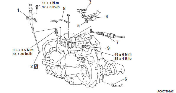
Removal steps
- Transmission fluid filler tube assembly
- O-ring
- A/T control solenoid valve assembly connector
- Input shaft speed sensor connector
- Transmission range switch connector
- Output shaft speed sensor connector
- Transaxle control cable connection
- Battery ground
- Harness clamp
- Transaxle assembly upper part coupling bolt
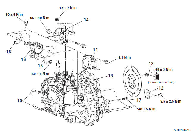
Removal steps
- Transmission fluid cooler hose assembly connection
- Water return hose A, Water return tube, Water return hose B
- Water-cooled transmission fluid cooler
- Oil pan cover
- Torque converter and drive plate coupling bolt
- Air intake plenum
- Raise the engine and transaxle assembly to the position where the engine weight is not applied to the transaxle mounting insulator
- Transaxle mounting bracket
- Transaxle mounting insulator stopper
- Transaxle mounting insulator
- Engine assembly holding
- transaxle assembly lower part coupling bolt
- transaxle assembly
REMOVAL SERVICE POINTS
TRANSAXLE ASSEMBLY UPPER PART COUPLING BOLT REMOVAL
Only loosen the bolts from the engine and transaxle assembly (do not remove).
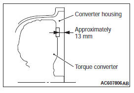
TORQUE CONVERTER AND DRIVE PLATE COUPLING BOLT REMOVAL
1. Remove the coupling bolts while turning the crankshaft.
2. Fully push the torque converter into the transaxle side so that it does not remain on the engine side.
TRANSAXLE MOUNTING BRACKET REMOVAL
1. Place a garage jack against the transaxle case with a piece of wood in between to support the engine and transaxle assembly.
2. Operate a garage jack so that the weight of the engine and transaxle assembly is not applied to the transaxle mounting insulator, and remove the transaxle mounting bracket.
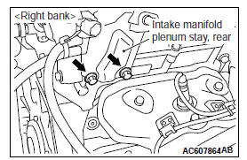
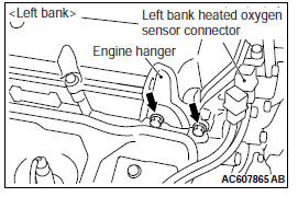
ENGINE ASSEMBLY HOLDING
CAUTION The engine hanger plate (special tool: MB992208)should be secured by tightening bolts with the engine hanger plate to the specified torque (If the other bolts are used, the engine assembly may fall down when it is raised.) Tightening torque: 22 +- 4 N*m (16 +- 2 ft-lb)
1. Remove the intake manifold plenum stay, rear on the right bank and the engine hanger on the left bank, and then install the engine hanger plate (Special tool: MB992208) to the place.
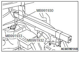
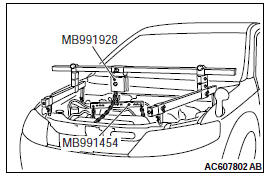
2. When engine hanger (Special tool: MB991928) is used
- Assemble the engine hanger (Special tool: MB991928).
(Set the components below to the base hanger.)
- Slide bracket (HI)
- Foot x 2 (standard) (MB991932)
- Foot x 2 (short) (MB991933)
- Joint x 2 (90) (MB991930)
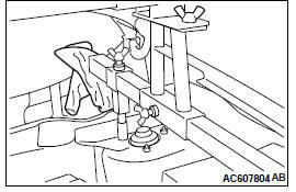
- Set the feet of the special tool as shown in the figure.
NOTE: Adjust the engine hanger balance by sliding the slide bracket (HI).
- Set the chains of the engine hanger (Special tool: MB991527) and the engine hanger balancer (Special tool: MB991454) to support the engine and transaxle assembly. Remove the garage jack and then remove the transaxle assembly upper part coupling bolts that have been loosened previously.
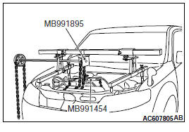
3. When using engine mechanical hanger (Special tool: MB991895)
- Set the foot of the engine mechanical hanger (Special tool: MB991895) as shown in the figure.
NOTE: Slide the front foot of the engine mechanical hanger (Special tool: MB991895) to balance the engine hanger.
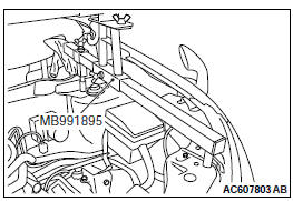
CAUTION Place rag between the engine mechanical hanger (Special tool: MB991895) and the windshield to prevent the special tool from interfering with the windshield.
- Set the chains of the engine hanger (Special tool: MB991527) and the engine hanger balancer (Special tool: MB991454) to support the engine and transaxle assembly. Remove the garage jack and then remove the transaxle assembly upper part coupling bolts that have been loosened previously.
INSTALLATION SERVICE POINTS
TRANSAXLE ASSEMBLY INSTALLATION
Fully push the torque converter into the transaxle side, and then assemble the transaxle assembly to the engine.
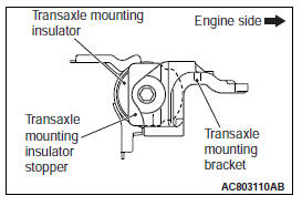
TRANSAXLE MOUNTING INSULATOR STOPPER INSTALLATION
Install the transaxle mounting insulator stopper as shown in the figure.
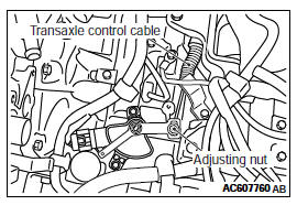
TRANSAXLE CONTROL CABLE (TRANSAXLE SIDE) INSTALLATION
1. Move the selector lever and manual control lever to the "N" position.
2. Use the adjusting nut to tighten the transaxle control cable to the specified torque.
Tightening torque: 9.5 +- 3.5 N*m (84 +- 30 in-lb)
Transfer Assembly <AWD>
REMOVAL AND INSTALLATION <VEHICLES WITH S-AWC>
Pre-removal and post-installation operation
- Under cover removal and installation
- Transmission fluid draining and refilling
- Transfer oil draining and refilling
- Propeller shaft removal and installation
- Front axle crossmember assembly removal and installation
- Drive shaft assembly <RH> removal and installation
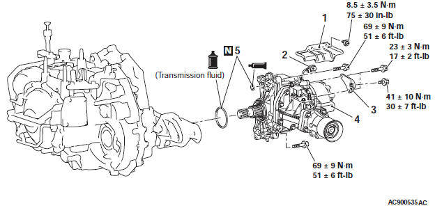
Removal steps
- Heat protector
- Connector connection
- Exhaust manifold bracket
- Transfer assembly
- O-ring
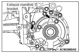
REMOVAL SERVICE POINT
EXHAUST MANIFOLD BRACKET
CAUTION Do not loosen the bolts other than shown.
REMOVAL AND INSTALLATION <Vehicles without S-AWC>
Pre-removal and post-installation operation
- Under cover removal and installation
- Transmission fluid draining and refilling
- Transfer oil draining and refilling
- Front exhaust pipe removal and installation
- Propeller shaft removal and installation
- Center member removal and installation
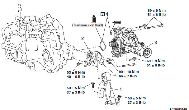
Removal steps
- Pressure hose assembly, return tube B, Hose bracket
- Rear roll stopper
- Transaxle case rear roll stopper bracket
- Drive shaft RH and output shaft
- Transfer assembly
- O-ring
REMOVAL SERVICE POINT
TRANSFER ASSEMBLY REMOVAL
Move the engine and transaxle assembly toward the front of the vehicle to make a gap between the engine/transaxle assembly and the crossmember. Pull out the transfer assembly through this gap.
Transaxle Control Module (TCM)
REMOVAL AND INSTALLATION
Pre-removal and post-installation operation
- Bottom cover assembly (driver's side) removal and installation
- Glove box assembly removal and installation
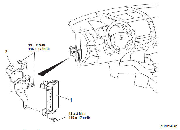
Removal steps
- TCM
- TCM bracket
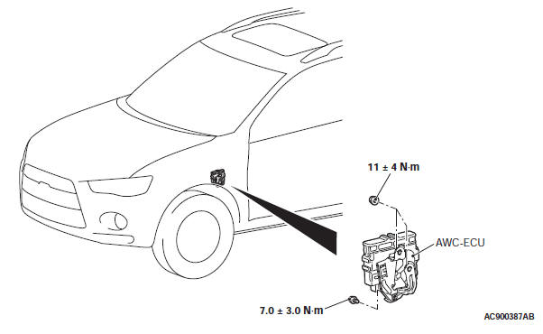
AWC-ECU <Vehicles With S-AWC>
REMOVAL AND INSTALLATION
Pre-removal and post-installation operation
- Removal and installation of the bottom cover assembly (driver's side)
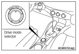
S-AWC CONTROL MODE SELECTOR <Vehicles with S-AWC>
REMOVAL AND INSTALLATION
Refer to GROUP 52A − Floor Console Assembly.
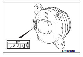
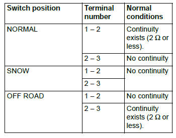
S-AWC CONTROL MODE SELECTOR INSPECTION
A/T Fluid Cooler Line
REMOVAL AND INSTALLATION
Pre-removal and post-installation operation
- Engine room under cover front, engine room side cover
- Front bumper extension A, B, transmission fluid cooler duct
- Engine coolant draining and refilling
- Transmission fluid draining and refilling
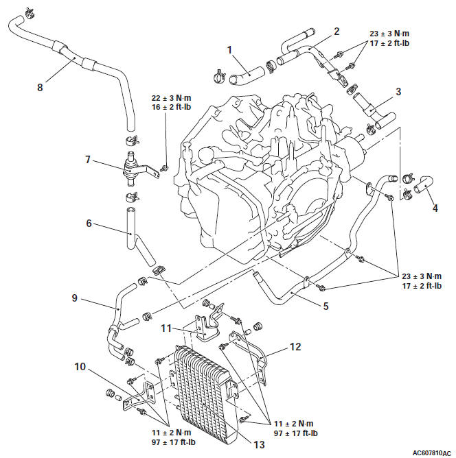
Removal steps
- Water return hose A
- Water return tube
- Water return hose B
- Water feed hose A
- Water feed tube
- Water feed hose B
- Thermo valve assembly
- Water feed hose C
- Transmission fluid cooler hose assembly
- Transmission fluid cooler bracket A
- Transmission fluid cooler bracket B
- Transmission fluid cooler bracket C
- Transmission fluid cooler assembly
THERMO VALVE CHECK
1. Obtain a container filled with water and place the thermo valve in it with a stick (approximately 6 mm in diameter) inserted. Gradually warm up the water while stirring, and check that the thermo valve opening temperature is within the standard value. The stick rises when the thermo valve opens.
Standard value: 75 +- 1.5ºC (167 +- 34.7 ºF)
2. Warm up the water to the full-open temperature of the thermo valve, and check that the valve lift amount is within the standard value.
Standard value: Full-open temperature 95ºC (203ºF)
or more
Valve lift amount when it is fully opened: 3 mm or
more
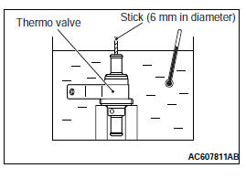
NOTE: Measure the height of the fully closed valve in advance, and then measure the valve height at fully open temperature to calculate the lift amount.
READ NEXT:
 Automatic Transaxle Overhaul
Transaxle Models
General Specifications
Service Specifications
Torque Specifications
Transaxle
Transfer
Size of torque wrench used
Adjusting Plate, Snap Ring,
Shim, Spacer, Needle Bearing,
Thrus
Transaxle
DISASSEMBLY AND ASSEMBLY
CAUTION
Use a fluid of the designated brand for transmission fluid. Use of
transmission fluid not specified
by the manufacturer can affect driveability and the durability
Side Cover
DISASSEMBLY AND ASSEMBLY
Side cover
D-ring
2-6 brake piston
D-ring
Spring retainer
Snap ring
Seal ring
Required special tools:
MB992196: Spring compressor
DISASSEMBLY
1. Remove the seal r
SEE MORE:
DTC P0741, P0742, P0743, P0748, P0753, P0758, P0763, P0768, P0815,
P0816, P0826, P0846
DTC P0741: Torque Converter Clutch System (Stuck Off), P0742 Torque
Converter Clutch System
(Stuck ON)
DESCRIPTIONS OF MONITOR METHODS
<P0741>
When the input shaft speed sensor is normal, the
engine speed signal is normal, and within the
lock-up operation range, the slip speed of the
tor
Automatic Transaxle Overhaul
Transaxle Models
General Specifications
Service Specifications
Torque Specifications
Transaxle
Transfer
Size of torque wrench used
Adjusting Plate, Snap Ring,
Shim, Spacer, Needle Bearing,
Thrust Washer and
Bearing Race
Retaining plate (For adjustment of Low-reverse brake clearance)
Retaining
