Mitsubishi Outlander: Side Cover
DISASSEMBLY AND ASSEMBLY
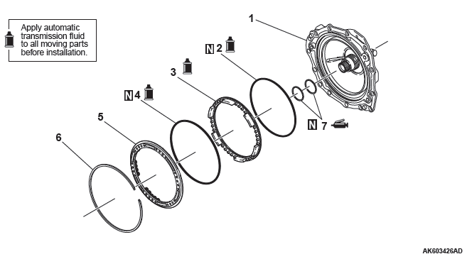
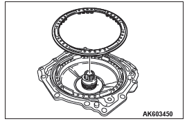
- Side cover
- D-ring
- 2-6 brake piston
- D-ring
- Spring retainer
- Snap ring
- Seal ring
Required special tools:
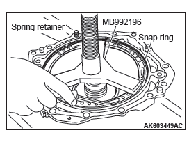
- MB992196: Spring compressor
DISASSEMBLY
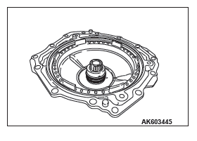
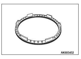
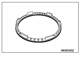
1. Remove the seal rings from the side cover.
CAUTION Ensure that the special tool MB992196 is correctly set, directly above the return springs of the spring retainer assembly.
2. Using the special tool MB992196, remove the snap ring while pushing the spring retainer assembly.
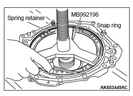
CAUTION Do not remove the return springs from the spring retainer assembly.
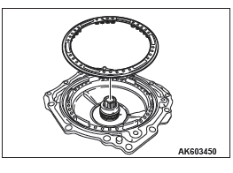
3. Remove the spring retainer assembly from the 2-6 brake piston.
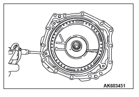
CAUTION Do not feed air abruptly. Otherwise, the 2-6 brake piston may become stuck in the side cover.
4. Feed air through the oil hole as indicated in the illustration to remove the 2-6 brake piston from the side cover.
5. Remove the D-rings from the 2-6 reverse brake piston.
ASSEMBLY
CAUTION
- Never reuse the D-rings.
- Apply transmission fluid to the D-rings before installation.
1. Install D-rings onto the 2-6 brake piston.
CAUTION Apply transmission fluid to the 2-6 brake piston before installation.
2. Install the 2-6 brake piston onto the side cover.
3. Install the spring retainer assembly onto the 2-6 brake piston.
CAUTION Ensure that the special tool MB992196 is correctly set, directly above the return springs of the spring retainer assembly.
4. Using the special tool MB992196, install the snap ring while pushing the spring retainer assembly.
CAUTION
- Never reuse the seal rings.
- Apply vaseline to the seal rings before installation.
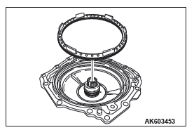
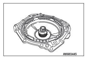
5. Install seal rings onto the side cover.
READ NEXT:
 Differential
DISASSEMBLY AND ASSEMBLY
Disassembly Steps
Final gear
Differential side bearing
(transmission case side)
Differential side bearing (converter
housing side)
Differential sub-assembly
Required
Transfer
DISASSEMBLY AND ASSEMBLY
<Vehicles with S-AWC>
Disassembly steps
Dust seal guard
Oil seal
O-ring
Dust seal
Oil seal
Cover
Transfer
<Vehicles without S-AWC>
Disassembly steps
Propeller Shaft
General Information
The 2-piece, 3-joint type propeller shaft with a center
bearing is adopted.
It has the following features:
The DOJ, which is of less sliding resistance, is
used for the No.2 jo
SEE MORE:
Brake fluid/Clutch fluid
The brake fluid and the clutch fluid share reservoir tank.
To check the fluid level
The fluid level must be between the “MAX” and “MIN” marks on the reservoir.
The fluid level is monitored by a float. When the fluid level falls below the
“MIN” mark, the brake fluid warning lamp li
Battery
GENERAL INFORMATION
The 80D26L battery has been adopted for 3.0L
engine.
The 75D23L battery has been adopted for 2.4L
engine.
ON-VEHICLE SERVICE
BATTERY CHECK
WARNING
Battery posts, terminals and related accessories contain
lead and lead compounds. WASH HANDS AFTER
HANDLING.
BATTERY VISUAL I
