Mitsubishi Outlander: Transfer
DISASSEMBLY AND ASSEMBLY
<Vehicles with S-AWC>
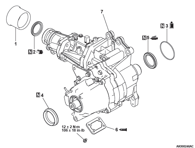
Disassembly steps
- Dust seal guard
- Oil seal
- O-ring
- Dust seal
- Oil seal
- Cover
- Transfer
<Vehicles without S-AWC>
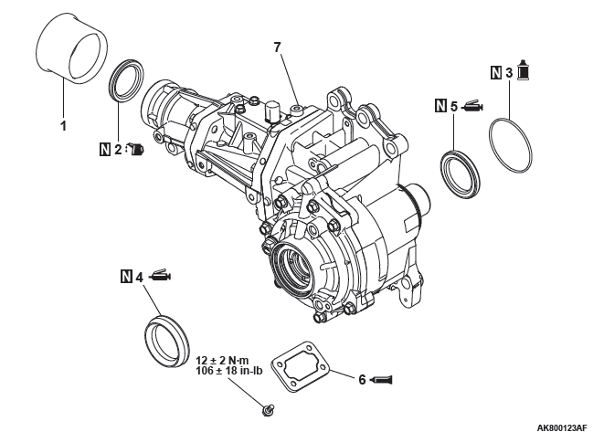
Disassembly steps
- Dust seal guard
- Oil seal
- O-ring
- Oil seal
- Oil seal
- Cover
- Transfer
Required special tools:
- MD998812: Installer cap
- MB992154: Oil seal installer
- MB992075: Handle
- MD998777: Camshaft oil seal installer adapter
- MD998713: Camshaft oil seal installer
- MB992142: Oil seal installer
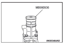
- MB990936: Installer adapter
ASSEMBLY SERVICE POINT
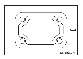
COVER INSTALLATION
1. Apply a 1.5 mm diameter bead of sealant as illustrated onto the cover.
3MATD Part No.8660 or equivalent
2. Attach the cover to the transfer and tighten it to the specified torque.
Tightening torque: 12 +- 2 N*m (106 +- 18 in-lb)
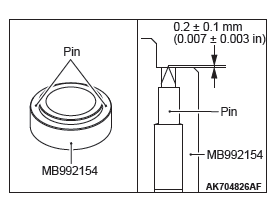
OIL SEAL INSTALLATION
CAUTION Pay attention to the transfer case that can possibly twist when the pin projection is too large.
1. Adjust the projection allowances of the two pins of the special tool, Oil Seal Installer (MB992154) to be 0.2 +- 0.1 mm (0.007 +- 0.003 in).
NOTE: The two pins are inserted into the special tool, Oil Seal Installer (MB992154). When the oil seal is replaced, the traces are found on the transfer case so that the replacement using the specified special tool can be recognized.
2. Apply specified grease to the oil seal lip area.
Specified grease: Retinax A
3. Using the special tool MD998812 and MB992154, install the oil seal.
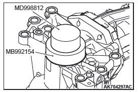
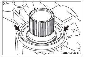
4. Check whether the two traces are found on the transfer case.
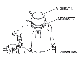
DUST SEAL INSTALLATION
1. Using the special tool MD998777 and MD998713, install the oil seal.
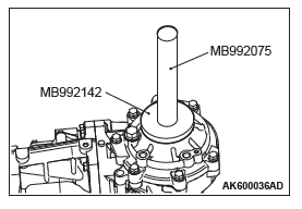
OIL SEAL INSTALLATION
1. Using the special tool MB992075 and MB992142, install the oil seal.
2. Apply specified grease to the oil seal lip area.
Specified grease: Retinax A
OIL SEAL INSTALLATION
1. Using the special tool MB990936, install the oil seal.
2. Apply transfer oil to the lip of oil seal.
READ NEXT:
 Propeller Shaft
General Information
The 2-piece, 3-joint type propeller shaft with a center
bearing is adopted.
It has the following features:
The DOJ, which is of less sliding resistance, is
used for the No.2 jo
Wheel and Tire
Specifications
The wheels and tires of the following specifications
have been established.
SPECIFICATIONS
ROAD WHEEL AND TIRE
<EXCEPT FOR CANADA>
<VEHICLES FOR CANADA>
SPARE WHEEL AND TI
Power Plant Mount
General Information
For the power plant support, the inertial axis
four-point mounting system is utilized, and the system
has the following features.
For the engine and transaxle mountings, the
cyl
SEE MORE:
Diagnostic Trouble Code Procedures
DTC 15: Cruise Control Switch System
Cruise Control Switch Circuit
CIRCUIT OPERATION
This circuit judges the signals of each switch
("ON/OFF", "CANCEL", "COAST/SET" and
"ACC/RES") of the cruise control switch. The ECM
detects the state of the cruise control switch by sensing
the voltages shown bel
On-vehicle Service
CHECK AT A/C-ECU TERMINAL
1. Disconnect the A/C compressor clutch connector to the A/C
compressor clutch.
2. Connect positive battery voltage directly to the connector for
the A/C compressor clutch.
3. If the A/C compressor clutch is normal, there will be a "click".
If the pulley and armature do
