Mitsubishi Outlander: Heater Unit, Heater Core, Blower Assembly and Evaporator Unit
HEATER UNIT AND FRONT DECK CROSSMEMBER ASSEMBLY REMOVAL AND INSTALLATION
Pre-removal operation
- Engine Coolant Draining
- Discharging refrigerant
- Front seat assembly removal
- Rear heater duct removal
- Instrument panel assembly removal
Post-installation Operation
- Instrument panel assembly installation
- Rear heater duct installation
- Front seat assembly installation
- Engine Coolant Refilling
- Charging refrigerant
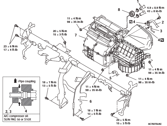
Removal steps
- Wiring harness and clamps
- Heater hose
- Heat protector
- Suction pipe
- Liquid pipe B
- O-ring
- Drain hose
- Front deck crossmember
- Heater unit assembly
REMOVAL SERVICE POINTS
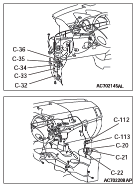
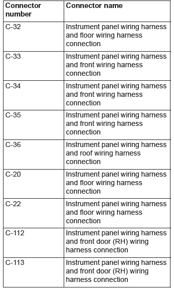
CONNECTOR DISCONNECTION
Disconnect the following connectors to remove the front deck crossmember.
SUCTION FLEXIBLE HOSE / LIQUID PIPE B DISCONNECTION
CAUTION Use the plug which is not breathable because A/C compressor oil or receiver have high hygroscopicity.
Plug the removed nipple of the pipe, hose and expansion valve to prevent the entry of dust and dirt.
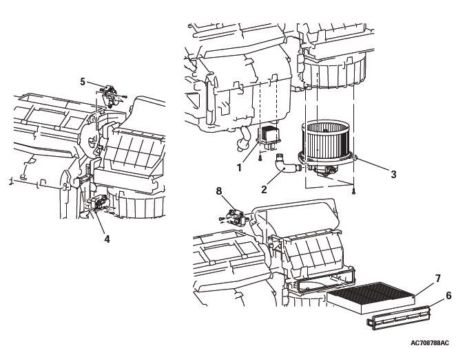
DISASSEMBLY AND ASSEMBLY
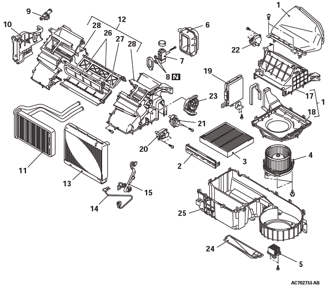
Disassembly steps
- Air intake duct
- Clean air filter cover
- Clean air filter
- Blower motor
- Power transistor
- Expansion valve cover
- Expansion valve
- O-ring
- Aspirator
- Heater pipe cover
- Heater core
- Upper case assembly
- Evaporator
- Air thermo sensor
- Wiring harness
- Blower case assembly
- Blower case, upper
- Blower case, lower
- A/C-ECU
- Air mixing damper control motor
- Mode selection damper control motor
- Outside/inside air selection damper control motor
- Mode selection damper lever
- Insulator
- Lower case
- Air mix damper
- Mode selection damper
- Upper case
INSPECTION
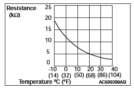
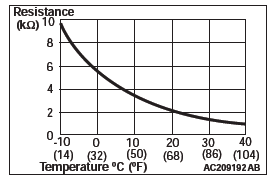
AIR THERMO SENSOR CHECK
Check that the resistance shown in the graph is almost satisfied when measuring the resistance between the terminals under two or more different temperature conditions.
NOTE: The temperature condition in checking should be within the range shown.
Motors and Transistor
REMOVAL AND INSTALLATION
Power transistor removal steps
- Bottom cover assembly (front passenger's seat)
- Power transistor
Blower motor removal steps
- Bottom cover assembly (front passenger's seat)
- Hose
- Blower motor
Air mixing damper control motor, mode selection damper control motor and outside/inside air selection damper control motor removal steps
- Glove box assembly
- Rear heater duct A
- A/C-ECU
- Air mixing damper control motor
- Mode selection damper control motor
- Clean air filter cover
- Clean air filter
- Outside/inside air selection damper control motor
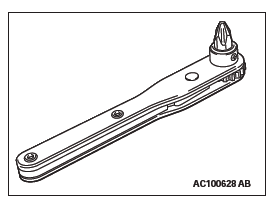
REMOVAL SERVICE POINT
AIR MIXING DAMPER CONTROL MOTOR, OUTSIDE/INSIDE AIR SELECTION DAMPER MOTOR, MODE SELECTION DAMPER CONTROL MOTOR REMOVAL
NOTE: A normal plate-type ratchet driver is recommended.
INSTALLATION SERVICE POINT
OUTSIDE/INSIDE AIR SELECTION DAMPER MOTOR INSTALLATION
Adjust the position of the outside/inside air selection damper while supporting it from the lower side through the hole which the clean air filter and the blower motor were removed.
INSPECTION
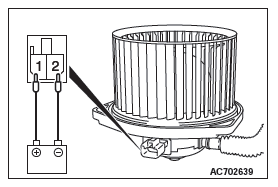
BLOWER MOTOR CHECK
Check that the motor turns when applying battery power between the connector terminals. Also check to see that there is no abnormal sound emitted from the motor at this time.
Ambient Air Temperature Sensor
REMOVAL AND INSTALLATION
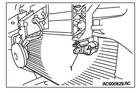
Removal steps
- Front bumper
- Ambient air temperature sensor
INSPECTION
AMBIENT AIR TEMPERATURE SENSOR CHECK
Measure the resistance between the sensor terminals under at least two temperatures. The resistance values should meet the values shown.
NOTE: The temperature should be within the shown range.
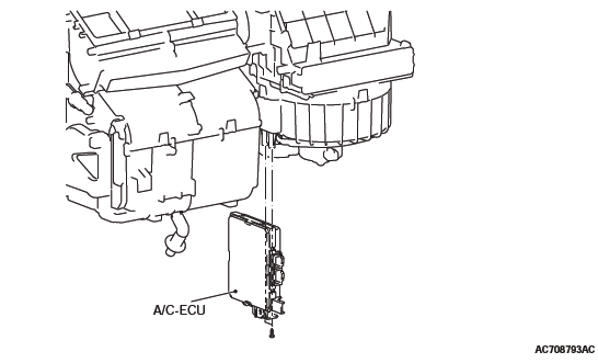
A/C-ECU
REMOVAL AND INSTALLATION
Pre-removal and Post-installation Operation
- Glove Box and Bottom Cover Assembly (passenger's side) Removal and Installation
- Foot duct Removal and Installation
READ NEXT:
 Compressor Assembly
REMOVAL AND INSTALLATION
Pre-removal Operation
Refrigerant Discharging
Front bumper under cover
Front under cover RH
Drive belt removal <2.4L>
Drive belt removal <3.0L>
Post-instal
Automatic Air Conditioning
General Information
The blower, heater, and evaporator have been integrated
with the heater and A/C system to achieve
greater fan power and noise reduction.
SAFETY PRECAUTIONS
WARNING
Wear safety gog
SEE MORE:
Engine oil
To check and refill engine oil
The engine oil used has a significant effect on the engine’s performance, service
life and startability. Be sure to use oil of the recommended quality and appropriate
viscosity.
All engines consume a certain amount of oil during normal operation. Therefore,
Antenna
Roof antenna
To remove
Turn the pole (A) anticlockwise.
To install
Screw the pole (A) clockwise into the base (B) until it is securely retained.
NOTE:
● Be sure to remove the roof antenna in the following cases:
• When going into an automatic car wash.
• When placing a car cover
