Mitsubishi Outlander: Driveshaft Assembly
REMOVAL AND INSTALLATION
CAUTION
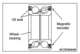
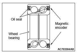
- The magnetic encoder collects metallic particles easily, because it is magnetized. Make sure that the magnetic encoder should not collect metallic particles. Check that there is not any trouble prior to reassembling it.
- When removing and installing the driveshaft assembly, make sure that the magnetic encoder (integrated with the inner oil seal) does not contact with surrounding parts to avoid damage.
- When removing and installing the front wheel speed sensor, make sure that the sensor head at the end does not contact with surrounding parts to avoid damage.
- The parts indicated by * are the nuts with friction coefficient stabilizer. In removal, ensure there is no damage, clean dust and soiling from the bearing and thread surfaces, and tighten them to the specified torque.
Pre-removal operation
- Transmission Fluid Draining <2.4 L engine>
- Automatic Transmission Fluid Draining <3.0 L engine>
Post-installation operation
- Using your fingers, press the Ball Joint Dust Cover to check for a crack or damage
- Transmission Fluid Filling <2.4 L engine>
- Automatic Transmission Fluid Filling <3.0 L engine>
<FWD>
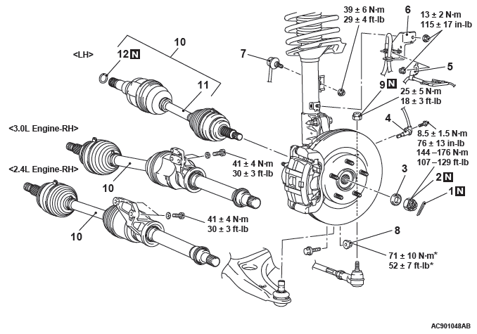
Removal steps
- Cotter pin
- Driveshaft nut
- Washer
- Front wheel speed sensor
- Front wheel speed sensor harness bracket
- Brake hose bracket
- Stabilizer link connection
- Self-locking nut (lower arm ball joint connection)
- Self-locking nut (tie-rod end connection)
- Driveshaft assembly
- Driveshaft
- Circlip
<AWD>
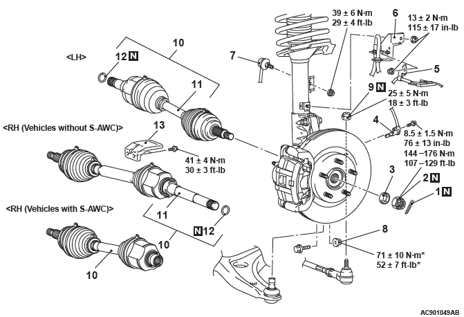
Removal steps
- Cotter pin
- Driveshaft nut
- Washer
- Front wheel speed sensor
- Front wheel speed sensor harness bracket
- Brake hose bracket
- Stabilizer link connection
- Self-locking nut (lower arm ball joint connection)
- Self-locking nut (tie-rod end connection)
- Driveshaft assembly
- Driveshaft
- Circlip
- Heat protector <3.0L engine without S-AWC>
Required Special Tools:
- MB990242: Puller Shaft
- MB990244: Puller Bar
- MB990767: Front Hub and Flange Yoke Holder
- MB991000: Spacer
- MB991017: Front Hub Remover and Installer
- MB991354: Puller Body
- MB991897 or MB992011: Ball Joint Remover
REMOVAL SERVICE POINTS
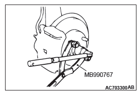
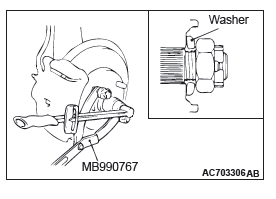
DRIVESHAFT NUT REMOVAL
CAUTION Do not apply the vehicle weight on the wheel bearing with the driveshaft nut loosened. Otherwise, the wheel bearing may be broken.
Use special tool MB990767 to counter the hub as shown in the figure to remove the driveshaft nut.
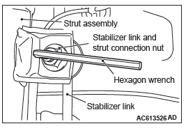
STABILIZER LINK DISCONNECTION
Use a hexagon wrench to remove the stabilizer link and strut connection nut as shown in the figure.

SELF-LOCKING NUT (TIE-ROD END CONNECTION) REMOVAL
CAUTION
- Loosen the self-locking nut (tie-rod end connection) from the ball joint, but do not remove here. Use the special tool.
- To prevent the special tool from dropping off, suspend it with a cord.
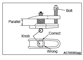
1. Install special tool MB991897 or MB992011, as shown in the figure.
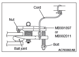
2. Turn the bolt and knob to make the special tool jaws parallel, then hand-tighten the bolt. After tightening, check that the jaws are still parallel.
NOTE: To adjust the special tool jaws to be parallel, set the orientation of the knob as shown in the figure.
3. Unscrew the bolt to disconnect the ball joint.
DRIVESHAFT ASSEMBLY REMOVAL
CAUTION
- The magnetic encoder collects metallic particles easily, because it is magnetized. Make sure that the magnetic encoder does not collect metallic particles.
- When removing the driveshaft, make sure that it does not contact with the magnetic encoder (integrated with the inner oil seal) to avoid damage.
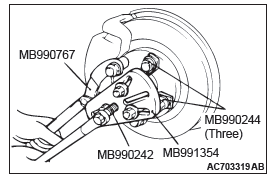
1. If the driveshaft is seized with the hub, use special tools MB990242 and MB990244, MB990767 and MB991354 to push the driveshaft assembly out from the hub.
2. While pulling the lower side of the brake disk toward you, remove the driveshaft assembly from the hub.
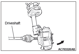
CAUTION
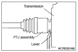
- Never pull out the driveshaft assembly from the EBJ assembly side. Otherwise, the PTJ assembly may be damaged. Always pull out from the PTJ side with a lever.
- Care must be taken to ensure that the oil seal of the transaxle is not damaged by the spline part of the driveshaft assembly.
3. For driveshafts other than FWD-RH driveshafts, insert a lever between the transaxle case or transfer and driveshaft assembly, and then pull the driveshaft assembly out from the transaxle.
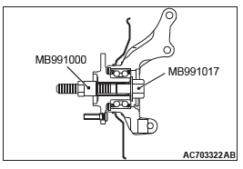
CAUTION
Do not apply the vehicle weight to the wheel bearing with the driveshaft assembly removed. If, however, the vehicle weight shall be applied to the bearing (in order to move the vehicle), tighten the following special tools MB991000 and MB991017 to the specified torque 144 − 176 N*m (107 − 129 ft-lb).
INSTALLATION SERVICE POINTS
DRIVESHAFT ASSEMBLY INSTALLATION
CAUTION
- The magnetic encoder collects metallic particles easily, because it is magnetized. Make sure that the magnetic encoder should not collect metallic particles. Check that there is not any trouble prior to reassembling it.
- When installing the driveshaft, make sure that it does not contact with the magnetic encoder (integrated with the inner oil seal) to avoid damage.
- Care must be taken to ensure that the oil seal of the transaxle is not damaged by the spline part of the driveshaft assembly.
STABILIZER LINK CONNECTION
Use a hexagon wrench to install the stabilizer link and strut connection nut as shown in the figure.
WASHER/DRIVESHAFT NUT INSTALLATION
CAUTION Do not apply the vehicle weight on the front wheel hub assembly before fully tightening the driveshaft nut. Otherwise, the wheel bearing may be broken.
1. Incorporate the driveshaft assembly washer as shown in the illustration.
2. Use special tool MB990767 to tighten the driveshaft nuts. At this time, tighten the nuts within the specified torque range considering the final tightening.
Tightening torque: 144 − 176 N*m (107 − 129 ft-lb)
3. If the pin holes do not align with the pins, tighten the driveshaft nut [less than 200 N*m(147 ft-lb) ] and find the nearest hole then bend the cotter pin to fit it.
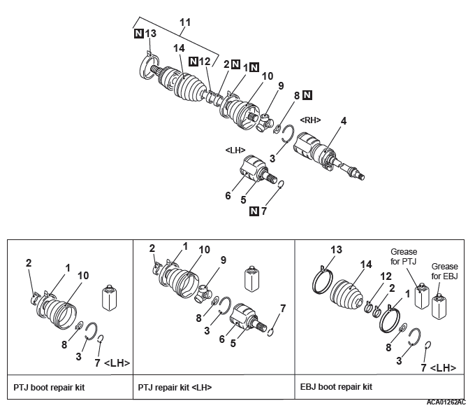
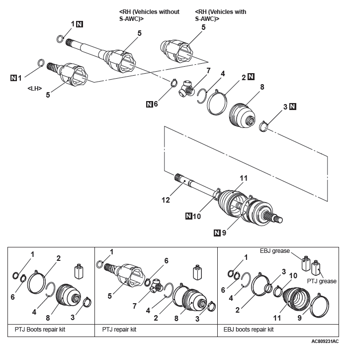
DISASSEMBLY AND ASSEMBLY <2.4L ENGINE- FWD>
CAUTION As for the EBJ assembly, only the EBJ boot can be replaceable, and other parts cannot be disassembled.
Disassembly steps
- PTJ boot band (large)
- PTJ boot band (small)
- Circlip
- PTJ case/Inner shaft assembly
- Dust cover <LH>
- PTJ case <LH>
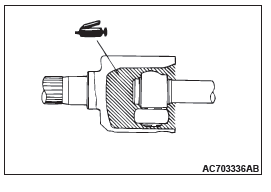
- Circlip
- Snap ring
- Spider assembly
- PTJ boot
- EBJ assembly
- EBJ boot band (small)
- EBJ boot band (large)
- EBJ boot
Required Special Tools:
- MB990810: Side Bearing Puller
- MB990890: Rear Suspension Bushing Base
- MB990930: Installer Adapter
- MB990932: Installer Adapter
- MB990934: Installer Adapter
- MB990938: Installer bar (snap-in type)
- MB991172: Inner Shaft Installer Base
- MD998369: Bearing Installer
- MD998801: Remover
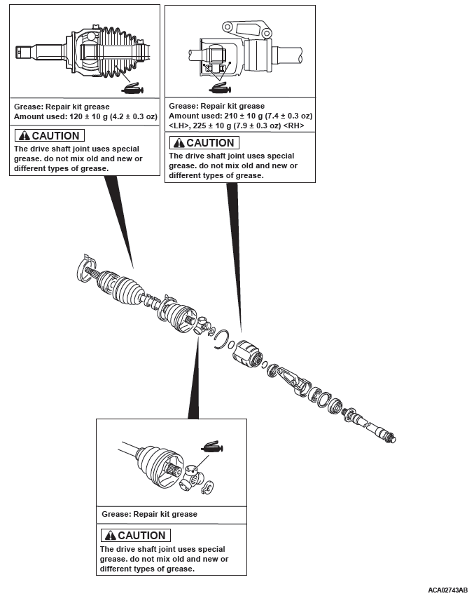
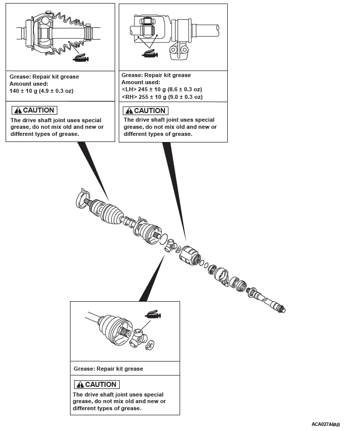
LUBRICATION POINTS
DISASSEMBLY SERVICE POINTS
PTJ CASE/INNER SHAFT ASSEMBLY REMOVAL
CAUTION When removing the PTJ case and inner shaft assembly, be careful not to drop off the roller part of spider assembly, because it easily departs from the spider assembly.
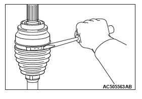
PTJ BOOT REMOVAL
1. Wipe off grease from the shaft spline.
2. When reusing the PTJ boot, wrap plastic tape around the shaft spline to avoid damaging the boot.
ASSEMBLY SERVICE POINTS
EBJ BOOT INSTALLATION
Wrap plastic tape around the shaft spline, and then install the EBJ boot.
PTJ BOOT INSTALLATION
Wrap plastic tape around the shaft spline, and then install the PTJ boot.
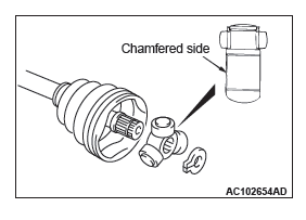
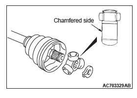
SPIDER ASSEMBLY INSTALLATION
CAUTION
- The drive shaft joint use special grease. Do not mix old and new or different types of grease.
- If the spider assembly has been cleaned, take special care to apply the specified grease.
1. Apply the specified grease furnished in the repair kit to the spider assembly between the spider axle and the roller.
Specified grease: Repair kit grease
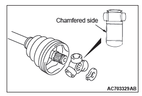
2. Install the spider assembly to the shaft from the direction of the spline chamfered side.
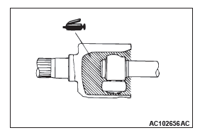
PTJ CASE/INNER SHAFT ASSEMBLY INSTALLATION
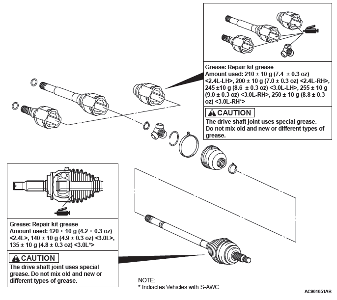
CAUTION The driveshaft joint uses special grease. Do not mix old and new or different types of grease.
After applying the specified grease to the PTJ case, insert the driveshaft and apply grease again.
Specified grease: Repair kit grease
Amount to use: 210 +- 10 g (7.4 +- 0.3 ounce) <LH>,
225 +- 10 g (7.9 +- 0.3 ounce) <RH>
NOTE: The grease in the repair kit should be divided in half for use, respectively, at the joint and inside the boot.
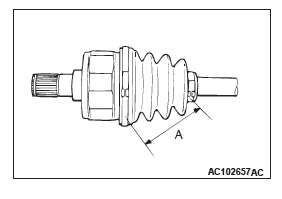
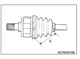
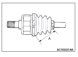
PTJ BOOT BAND (SMALL)/PTJ BOOT BAND (LARGE) INSTALLATION
Set the PTJ boot bands at the specified distance in order to adjust the amount of air inside the PTJ boot, and then tighten the PTJ boot band (small), PTJ boot band (large) securely.
Standard value (A): 85 +- 3 mm (3.35 +- 0.12 inches)
DISASSEMBLY AND ASSEMBLY <3.0L ENGINE- FWD>
CAUTION As for the EBJ assembly, only the EBJ boot can be replaceable, and other parts cannot be disassembled.
Disassembly steps
- PTJ boot band (large)
- PTJ boot band (small)
- Circlip
- PTJ case and inner shaft assembly <RH>
- Dust cover <LH>
- PTJ case <LH>
- Circlip
- Snap ring
- Spider assembly
- PTJ boot
- EBJ assembly
- EBJ boot band (small)
- EBJ boot band (large)
- EBJ boot
Required Special Tools:
- MB990810: Side Bearing Puller
- MB990890: Rear Suspension Bushing Base
- MB990930: Installer Adapter
- MB990932: Installer Adapter
- MB990934: Installer Adapter
- MB990938: Installer Bar (snap-in type)
- MB991172: Inner Shaft Installer Base
- MD998369: Bearing Installer
- MD998801: Remover
LUBRICATION POINTS
DISASSEMBLY SERVICE POINTS
PTJ CASE/INNER SHAFT ASSEMBLY REMOVAL
CAUTION When removing the PTJ case and inner shaft assembly, be careful not to drop off the roller part of spider assembly, because it easily departs from the spider assembly.
PTJ BOOT REMOVAL
1. Wipe off grease from the shaft spline.
2. When reusing the PTJ boot, wrap plastic tape around the shaft spline to avoid damaging the boot.
ASSEMBLY SERVICE POINTS
EBJ BOOT INSTALLATION
Wrap plastic tape around the shaft spline, and then install the EBJ boot.
PTJ BOOT INSTALLATION
Wrap plastic tape around the shaft spline, and then install the PTJ boot.
SPIDER ASSEMBLY INSTALLATION
CAUTION
- The driveshaft joint use special grease. Do not mix old and new or different types of grease.
- If the spider assembly has been cleaned, take special care to apply the specified grease.
1. Apply the specified grease furnished in the repair kit to the spider assembly between the spider axle and the roller.
Specified grease: Repair kit grease 2. Install the spider assembly to the shaft from the direction of the spline chamfered side.
PTJ CASE AND INNER SHAFT ASSEMBLY INSTALLATION
CAUTION The driveshaft joint use special grease. Do not mix old and new or different types of grease.
After applying the specified grease the PTJ case, insert the driveshaft and apply grease one more time.
Specified grease: Repair kit grease
Amount to use:
245 +- 10 g (8.6 +- 0.3 ounce) <LH>
255 +- 10 g (9.0 +- 0.3 ounce) <RH>
NOTE: The grease in the repair kit should be divided in half for use, respectively, at the joint and inside the boot.
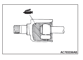
PTJ BOOT BAND (SMALL)/PTJ BOOT BAND (LARGE) INSTALLATION
Set the PTJ boot bands at the specified distance in order to adjust the amount of air inside the PTJ boot, and then tighten the PTJ boot band (small), PTJ boot band (large) securely.
Standard value (A):
95 +- 3 mm (3.74 +- 0.12 inches)
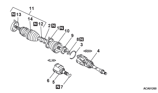
DISASSEMBLY AND ASSEMBLY <AWD>
CAUTION
- As for the EBJ assembly, only the EBJ boot can be replaceable, and other parts cannot be disassembled.
- The EBJ boot for 3.0L Engine-RH is not replaceable.
Disassembly steps
- Circlip
- PTJ boot band (large)
- PTJ boot band (small)
- Circlip
- PTJ case
- Snap ring
- Spider assembly
- PTJ boot
- EBJ boot band (large)
- EBJ boot band (small)
- EBJ boot
- EBJ assembly
LUBRICATION POINTS
DISASSEMBLY SERVICE POINT
PTJ CASE/SPIDER ASSEMBLY REMOVAL
CAUTION
When removing the PTJ case, be careful not to drop off the roller part of spider assembly, because it easily departs from the spider assembly.
1. Wipe off grease from the spider assembly and the inside of the PTJ case.
2. Always clean the spider assembly when the grease contains water or foreign material.
PTJ BOOT REMOVAL
1. Wipe off the grease on the shaft spline.
2. When reusing the TJ boot, wrap plastic tape around the shaft spline to avoid damaging the boot.
ASSEMBLY SERVICE POINT
PTJ BOOT INSTALLATION
Apply a tape to the shaft spline area. Then incorporate the PTJ boot band (small) and PTJ boot.
SPIDER ASSEMBLY/PTJ CASE INSTALLATION
CAUTION
- The driveshaft joint use special grease. Do not mix old and new or different types of grease.
- If the spider assembly has been cleaned, take special care to apply the specified grease.
1. Apply the specified grease furnished in the repair kit to the spider assembly between the spider axle and the roller.
Specified grease: Repair kit grease
2. Install the spider assembly to the shaft from the direction of the spline chamfered side.
3. After applying the specified grease to the PTJ case, insert the driveshaft and apply grease one more time.
Specified grease: Repair kit grease
Amount to use:
210 +- 10 g (7.4 +- 0.3 ounce) <2.4L Engine-LH>
200 +- 10 g (7.0 +- 0.3 ounce) <2.4L Engine-RH>
245 +- 10 g (8.6 +- 0.3 ounce) <3.0L Engine-LH>
255 +- 10 g (9.0 +- 0.3 ounce) <3.0L Engine-RH>
250 +- 10 g (8.8 +- 0.3 ounce) <3.0L Engine-RH with
S-AWC>
NOTE: When using the repair kit grease, fill the half of the grease into the joint and the other half into the boot as a guideline, and consume the grease completely.
PTJ BOOT BAND (SMALL)/PTJ BOOT BAND (LARGE) INSTALLATION
Adjust the distance (A shown in the illustration) between the boot bands to the standard value to adjust the air volume inside the PTJ boot to the specified value, then be sure to tighten the PTJ boot band (large) and PTJ boot band (small).
Standard value (A):
85 +- 3 mm (3.35 +- 0.12 inches) <2.4L Engine>
95 +- 3 mm (3.74 +- 0.12 inches) <3.0L Engine>
INSPECTION
- Check the driveshaft for damage, bending or corrosion.
- Check the inner shaft for damage, bending or corrosion.
- Check the output shaft for damage, bending or corrosion.
- Check the driveshaft spline part for wear or damage.
- Check the inner shaft spline part for wear or damage.
- Check the output shaft spline part for wear or damage.
- Check the spider assembly for roller rotation, wear or corrosion.
- Check the groove inside PTJ case for wear or corrosion.
- Check the boots for deterioration, damage or cracking.
- Check the center bearing for seizure, discoloration or roughness of rolling surface.
- Check the dust cover for damage or deterioration.
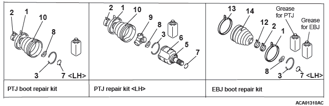
EBJ BOOT REPLACEMENT
Required Special Tool:
- MB991561:Boot Band Crimping Tool
1. Remove the boot bands (large and small).
NOTE: The boot bands cannot be re-used.
2. Remove the EBJ boot.
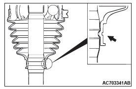
3. Wrap a plastic tape around the shaft spline, and assemble the boot band and EBJ boot.
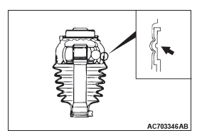
4. Align the center groove on the EBJ boot small end with the shaft groove.
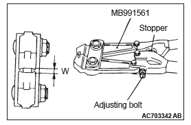
5. Turn the adjusting bolt on special tool MB991561 so that the size of the opening (W) is at the standard value.
Standard value (W): 2.9 mm (0.11 inch)
- If it is larger than 2.9 mm (0.11 inch)
Tighten the adjusting bolt. - If it is smaller than 2.9 mm (0.11 inch)
Loosen the adjusting bolt.
NOTE: The value of W will change by approximately 0.7 mm (0.03 inch) for each turn of the adjusting bolt.
NOTE: The adjusting bolt should not be turned more than once.
6. Position the EBJ boot band (small) so that there is even clearance at either end (A and B).
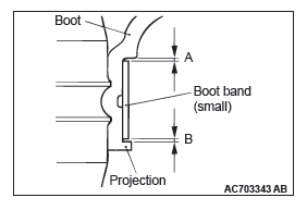
CAUTION
- Secure the driveshaft in an upright position and clamp part of the boot band to be crimped securely in the jaws of the special tool MB991561.
- Crimp the boot band until special tool MB991561 touches the stopper.
7. Use special tool MB991561 to crimp the boot band (small).

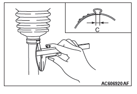
8. Check that the crimping amount (C) of the boot band is at the standard value.
Standard value (C): 2.4 − 2.8 mm (0.10 − 0.11 inch)
If the crimping amount is larger than 2.8 mm (0.11
inch)
Readjust the value of (W) in step 5 according to the
following formula, and then repeat the operation in
step 7.
W = 5.5 mm (0.22 inch) − C
Example: If C = 2.9 mm (0.11 inch), then W = 2.6 mm
(0.10 inch)
If the crimping amount is smaller than 2.4 mm (0.10
inch)
Remove the EBJ boot band, readjust the value of
(W) in step 5 according to the following formula,
and then repeat the operations in steps 6 and 7
using a new EBJ boot band.
W = 5.5 mm (0.22 inch) − C
Example: If C = 2.3 mm (0.09 inch), then W = 3.2
mm (0.13 inch)
9. Check that the boot band is not sticking out past the place where it has been installed. If the boot band is sticking out, remove it and then repeat steps 6 to 8, using a new boot band.
CAUTION The driveshaft joint uses special grease. Do not mix old and new or different types of grease.
10.Fill the inside of the boot with the specified amount of the specified grease.
Specified grease: Repair kit grease
Amount to use: 120 +- 10 g (4.2 +- 0.3 ounces) <2.4L
Engine>
Amount to use: 140 +- 10 g (4.9 +- 0.3 ounces) <3.0L
Engine>
11.Align the center groove on the EBJ boot big end with the EBJ case groove.
12.Follow the same procedure as in step 5 to adjust the size of the opening (W) on the special tool so that it is at the standard value.
Standard value (W): 3.2 mm (0.13 inch)
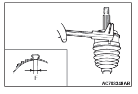
13.Position the EBJ boot band (large) so that there is even clearance at either end (D and E).
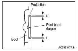
14.Use special tool MB991561 to crimp the EBJ boot band (large) in the same way as in step 7.
15.Check that the crimping amount (F) of the boot band is at the standard value.
Standard value (F): 2.4 − 2.8 mm (0.10 − 0.11 inch)
If the crimping amount is larger than 2.8 mm (0.11
inch)
Readjust the value of (W) in step 12 according to
the following formula, and then repeat the operation
in step 14.
W = 5.8 mm (0.23 inch) − F
Example: If F = 2.9 mm (0.11 inch), then W = 2.9 mm
(0.11 inch)
If the crimping amount is smaller than 2.4 mm (0.10
inch)
Remove the EBJ boot band, readjust the value of
(W) in step 12 according to the following formula,
and then repeat the operations in steps 13 and 14
using a new EBJ boot band.
W = 5.8 mm (0.23 inch) − F
Example: If F = 2.3 mm (0.09 inch), then W = 3.5 mm
(0.14 inch)
16.Check that the boot band is not sticking out past the place where it has been installed. If the boot band is sticking out, remove it and then repeat steps 13 to 15, using a new boot band.
READ NEXT:
 Basic Brake
General Information
Brake systems with higher reliability and durability
have achieved distinguished braking performance.
FEATURES
IMPROVEMENT OF BRAKING PERFORMANCE
In addition to the 10-inch singl
Basic Brake System
Diagnosis
INTRODUCTION TO BASIC BRAKE SYSTEM DIAGNOSIS
Hydraulic brakes are composed of the brake pedal,
master cylinder, brake booster and disc brakes. Malfunctions
such as insufficient braking power or the
ge
SEE MORE:
Wheel and Tire
Specifications
The wheels and tires of the following specifications
have been established.
SPECIFICATIONS
ROAD WHEEL AND TIRE
<EXCEPT FOR CANADA>
<VEHICLES FOR CANADA>
SPARE WHEEL AND TIRE
NOTE: The * mark indicates optional item.
NOTE: PCD (Pitch Circle Diameter) indicates the pitch
Hands-free Bluetooth® cellular phoneinterface system with voice recognition
The Hands-free Bluetooth® cellular phone interface system with voice recognition
uses a wireless communication technology known as Bluetooth® to allow you to make
hands-free calls in your vehicle using your Bluetooth® compatible cellular phone
with Hands-free profile.
The system is equippe
