Mitsubishi Outlander: Stabilizer Bar
REMOVAL AND INSTALLATION
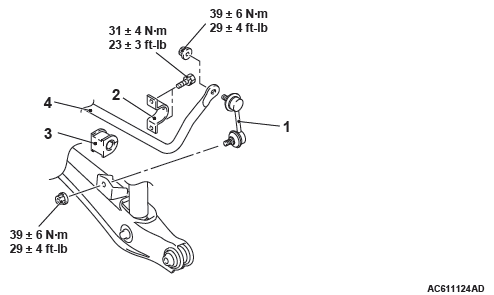
<2.4L Engine: 5 persons seat>
<2.4L Engine: 7 persons seat, 3.0L Engine>
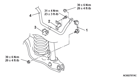
Removal steps
- Stabilizer link
- Stabilizer bracket
- Bushing
- Rear differential carrier assembly
- Stabilizer bar
INSTALLATION SERVICE POINT
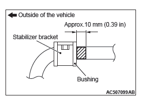
STABILIZER BAR/BUSHING/STABILIZER BRACKET INSTALLATION
<2.4L Engine: 5 persons seat>
Position the identification mark of the stabilizer bar at the left side of the vehicle as shown in the figure, and tighten the stabilizer bracket mounting nut.
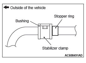
<2.4L Engine: 7 persons seat, 3.0L Engine>
Install the stabilizer bracket as shown in the figure, and tighten the stabilizer bracket mounting nut.
INSPECTION
- Check the bushings for wear and deterioration.
- Check the stabilizer bar for deterioration or damage.
- Check all bolts for condition and straightness.
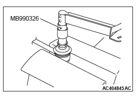
STABILIZER LINK BALL JOINT ROTATION TORQUE CHECK
1. Move the stabilizer link ball joint stud back and forth for several times, install the stud with nut, and measure the stabilizer link ball joint rotation torque using the preload socket (Special tool: MB990326).
Standard value: 0.5 − 2.9 N*m (4.4 − 25.7 in-lb)
2. When the measured value exceeds the standard range, replace the stabilizer link.
3. When the measured value is lower than the standard value, check the stabilizer link ball joint that there is no looseness or gritty feeling. If there is no looseness or gritty feeling, it is judged as usable.
STABILIZER LINK BALL JOINT COVER CHECK
1. Using your fingers, press the dust cover to check for a crack or damage.
2. If the dust cover has a crack or damage, replace the stabilizer link.
NOTE: If the dust cover has a crack or damage, the ball joint could be damaged. If the dust cover is damaged during maintenance, replace it.
Rear Suspension Crossmember
REMOVAL AND INSTALLATION
CAUTION
- The parts indicated by * are the bolts with friction coefficient stabilizer. In removal, ensure there is no damage, clean dust and soiling from the bearing and thread surfaces, and tighten them to the specified torque.
Pre-removal operation
- Control link arm removal
- Upper arm removal
- Rear suspension stabilizer bar removal
- Center exhaust pipe removal
- Driveshaft removal
- Rear differential assembly removal
Post-installation operation
- Rear differential assembly installation
- Driveshaft installation
- Center exhaust pipe installation
- Rear suspension stabilizer bar installation
- Upper arm installation
- Control link installation
- Rear wheel alignment check and adjustment
<FWD>, <AWD>
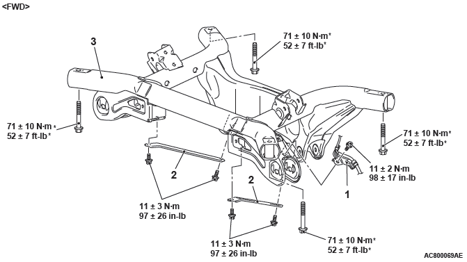
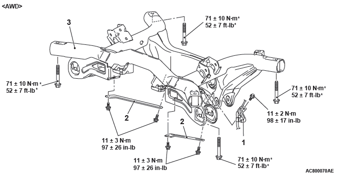
Removal steps
- Rear wheel speed sensor clamp
- Rear suspension crossmember stay
- Rear suspension crossmember
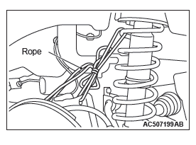
REMOVAL SERVICE POINT
REAR SUSPENSION CROSSMEMBER REMOVAL <2.4 L ENGINE: 5 PERSONS SEAT>
To avoid the break hose load, fix the trailing arm assembly with a rope as shown in the figure.
READ NEXT:
 Front Axle
General Information
For the front axle, the unit ball bearing (double-row
angular contact ball bearing) with an integral oil seal
is used as a wheel bearing, and EBJ-PTJ type constant
velocity joint a
Front Axle Diagnosis
TROUBLESHOOTING STRATEGY
Use these steps to plan your diagnostic strategy. If
you follow them carefully, you will be sure that you
have exhausted most of the possible ways to find a
front axle fault.
Front Axle Hub Assembly
REMOVAL AND INSTALLATION
CAUTION
The magnetic encoder collects metallic particles easily, because it
is magnetized. Make sure that
the magnetic encoder should not collect metallic particles. Che
SEE MORE:
Transaxle Control
REMOVAL AND INSTALLATION
CAUTION
Before removing the clock spring connector, refer to GROUP 52B − SRS Air Bag
Service Precautions
and Air Bag Module and Clock Spring.
Pre-removal operation
Front floor console assembly removal
Post-installation operation
Front floor console assembly ins
Power steering system
When the engine is stopped, the power steering system will not function and it
will require greater manual effort to operate the steering wheel. Keep this in mind
in particular when towing the vehicle. Never turn off the engine while driving.
Periodically check the power steering fluid level.
