Mitsubishi Outlander: Front Axle Hub Assembly
REMOVAL AND INSTALLATION
CAUTION
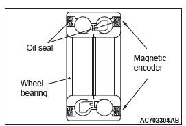
- The magnetic encoder collects metallic particles easily, because it is magnetized. Make sure that the magnetic encoder should not collect metallic particles. Check that there is not any trouble prior to reassembling it.
- When removing and installing the front wheel hub assembly, make sure that the magnetic encoder (integrated with the inner oil seal) does not contact with surrounding parts to avoid damage.
- When removing and installing the front wheel speed sensor, make sure that the sensor head at the end does not contact with surrounding parts to avoid damage.
- The parts indicated by * are the nuts with friction coefficient stabilizer. In removal, ensure there is no damage, clean dust and soiling from the bearing and thread surfaces, and tighten them to the specified torque.
Post-installation operation
- Using your fingers, press the Ball Joint Dust Cover to check for a crack or damage.
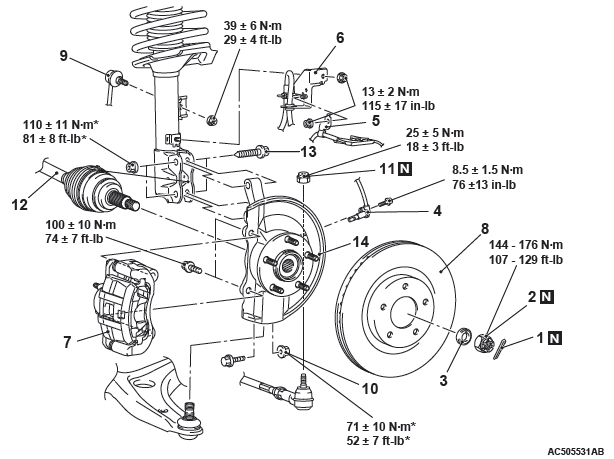
Removal steps
- Cotter pin
- Driveshaft nut
- Washer
- Front wheel speed sensor
- Front wheel speed sensor harness bracket
- Brake hose bracket
- Caliper assembly
- Brake disk
- Stabilizer link connection
- Self-locking nut (lower arm ball joint connection)
- Self-locking nut (tie-rod end connection)
- Driveshaft and hub knuckle assembly connection
- Hub knuckle assembly and strut mounting bolt and nuts
- Hub knuckle assembly
Required Special Tools:
- MB990242: Puller Shaft
- MB990244: Puller Ball
- MB990767: Front Hub and Flange Yoke Holder
- MB991354: Puller Body
- MB991897 or MB992011: Ball Joint Remover
REMOVAL SERVICE POINTS
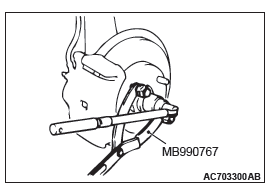
DRIVESHAFT NUT REMOVAL
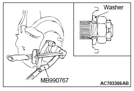
CAUTION Do not apply the vehicle weight on the front wheel hub assembly with the driveshaft nut loosened. Otherwise, the wheel bearing may be broken.
Use special tool MB990767 to counter the hub as shown in the figure to remove the driveshaft nut.
CALIPER ASSEMBLY REMOVAL
1. Remove the caliper assembly with brake hose.
2. Secure the removed caliper assembly with a wire or other similar material at a position where it will not interfere with the removal and installation of the hub knuckle assembly.
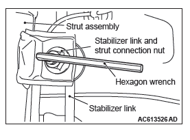
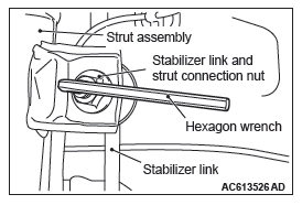
STABILIZER LINK DISCONNECTION
Use a hexagon wrench to remove the stabilizer link and strut connection nut as shown in the figure.
SELF-LOCKING NUT (TIE-ROD END CONNECTION) REMOVAL
CAUTION
- Loosen the self-locking nut (tie-rod end connection) from the ball joint, but do not remove here. Use the special tool.
- To prevent the special tool from dropping off, suspend it with a cord.
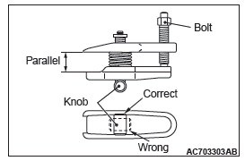
1. Install special tool MB991897 or MB992011 as shown in the figure.
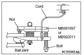
2. Turn the bolt and knob to make the special tool jaws parallel, then hand-tighten the bolt. After tightening, check that the jaws are still parallel.
NOTE: To adjust the special tool jaws to be parallel, set the orientation of the knob as shown in the figure.
3. Unscrew the bolt to disconnect the ball joint.
DRIVESHAFT AND HUB KNUCKLE ASSEMBLY DISCONNECTION
CAUTION
- The magnetic encoder collects metallic particles easily, because it is magnetized. Make sure that the magnetic encoder does not collect metallic particles.
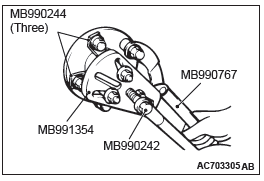
- When removing the driveshaft, make sure that it does not contact with the magnetic encoder (integrated with the inner oil seal) to avoid damage.
If the driveshaft is seized, use special tools MB990242 and MB990244, MB991354 and MB990767 to push the driveshaft out from the hub.
INSTALLATION SERVICE POINTS
STABILIZER LINK CONNECTION
Use a hexagon wrench to install the stabilizer link and strut connection nut as shown in the figure.
WASHER/DRIVESHAFT NUT INSTALLATION
CAUTION
- The magnetic encoder collects metallic particles easily, because it is magnetized. Make sure that the magnetic encoder should not collect metallic particles. Check that there is not any trouble prior to reassembling it.
- When installing the driveshaft, make sure that it does not contact with the magnetic encoder (integrated with the inner oil seal) to avoid damage.
- Do not apply the vehicle weight on the wheel bearing before fully tightening the driveshaft nut. Otherwise, the wheel bearing may be broken.
1. Be sure to install the driveshaft washer in the illustrated direction.
2. Use special tool MB990767 to tighten the driveshaft nuts. At this time, tighten the nuts within the specified torque range considering the final tightening.
Tightening torque: 144 − 176 N*m (107 − 129 ft-lb)
3. If the pin holes do not align with the pins, tighten the driveshaft nut [less than 200 N*m(147 ft-lb) ] and find the nearest hole then bend the cotter pin to fit it.
INSPECTION
- Check the hub for cracks and spline for wear.
- Check the knuckle for cracks.
- Check for defective bearing.
NOTE: If the meshing of the wheel bearing outer race and the knuckle, or of the wheel bearing inner race and the hub, is loose, replace the bearing or damaged parts.
DISASSEMBLY AND ASSEMBLY
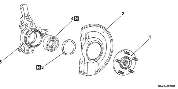
Disassembly steps
- Hub
- Dust shield
- Snap ring
- Wheel bearing
- Knuckle
Assembly steps
- Knuckle
- Wheel bearing
- Snap ring
- Dust shield
- Hub
- Hub starting torque check
- Wheel bearing end play check
Required Special Tools:
- MB990326: Preload Socket
- MB990890: Rear Suspension Bushing Base
- MB990935: Installer Adapter
- MB990938: Installer Bar
- MB991000: Spacer
- MB991017: Front Hub Remover and Installer
- MB991355: Knuckle Arm Bridge
- MB991388: Bush Remover Base
- MB991576: Base
- MB992150: Oil Seal Installer
- MB992250: Knuckle Arm Bridge Attachment
- MD999528: Adapter
- MD998801: Remover
- MD998812: Installer Cap
- MD998813: Installer
DISASSEMBLY SERVICE POINTS
HUB REMOVAL
CAUTION In the hub removal operation, make sure to replace the wheel bearing with new one.
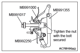
1. Replace special tool MB992250 with a guide of special MB991355 as shown in the figure.
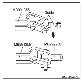
2. Insert special tool MB992250 in the knuckle and tighten it with a bolt and nut.
NOTE: Set the spacers of special tool MB992250 as shown in the figure.
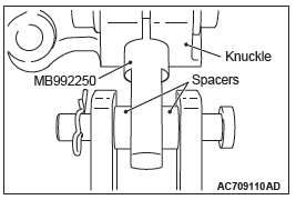
3. Use special tools MB991000, MB991017, MB991355 and MB992250 to remove the hub.
WHEEL BEARING REMOVAL
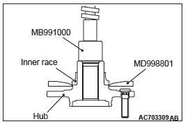
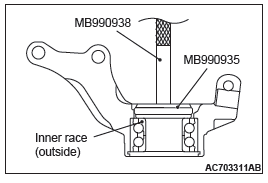
1. Use special tools MD998801 and MB991000 to remove the wheel bearing inner race (outside) from the hub.
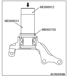
2. Use special tools MB992150, MD998812 and MD998813 to assemble the inner race (outside) removed from the hub to the wheel bearing.
3. Use special tools MB990935 and MB990938 to remove the wheel bearing.
ASSEMBLY SERVICE POINTS
WHEEL BEARING INSTALLATION
CAUTION
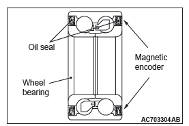
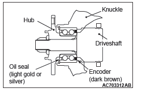
- The magnetic encoder for wheel speed sensor is installed in the wheel bearing. Install the wheel bearing so that the encoder is positioned in the direction shown in the figure.
- When press-fit the wheel bearing, push the outer race.
- After press-fit the wheel bearing, wipe off the extra grease in order not to remain on the magnetic encoder.
1. Remove grease and foreign material cleanly from the inside of knuckle bore.
2. Apply the specified grease thinly and evenly to the inside of knuckle as shown in the figure.
Specified grease: Dowcorning/Molykote BR2 Plus Amount to use: as required {1.0 − 1.5 g (0.04 −0.05 ounce) }
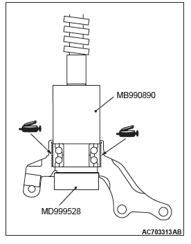
3. Use special tools MB990883 and MB 990890 to press-fit the wheel bearing.
4. Remove excessive grease seeped out between knuckle and wheel bearing outer race after press-fitting the wheel bearing.
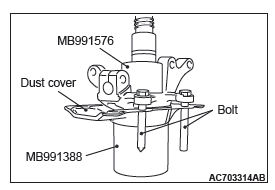
DUST SHIELD INSTALLATION
Use special tools MB991388 and MB991576 to press-fit the knuckle into the dust shield.
NOTE: Use the bolts (M12) to align the caliper mounting holes.
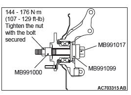
HUB ROTATION STARTING TORQUE CHECK
1. Set special tools MB991000 and MB991017 as shown in the figure, tighten the nut to the specified torque, and press-fit the hub into the knuckle.
Tightening torque: 144 − 176 N*m (107 − 129 ft-lb)
2. Rotate the hub to make the bearing well-greased.
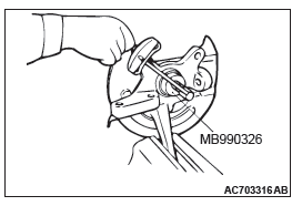
3. Use Special tool MB990326 to measure the hub rotation starting torque.
Limit: 1.5 N*m (13 in-lb)
4. Hub rotation starting torque should be within the limit value, and there should be no roughness and gritty feeling in rotation.
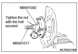
WHEEL BEARING END PLAY CHECK
1. Use special tools MB991000 and MB991017 to measure to determine whether the wheel bearing end play is within the specified limit or not.
Limit: 0.05 mm(0.002 inch)
2. If the end play is not within the limit range while the nut is tightened to specified torque, the bearing, hub and/or knuckle have probably not been installed correctly. Replace the bearing and re-install.
Tightening torque: 144 − 176 N*m (107 − 129 ft-lb)
INSPECTION
- Check the front hub and brake disc mounting surfaces for galling and contamination.
- Check the knuckle inner surface for galling and cracks.
READ NEXT:
 Driveshaft Assembly
REMOVAL AND INSTALLATION
CAUTION
The magnetic encoder collects metallic particles easily, because it
is magnetized. Make sure that
the magnetic encoder should not collect metallic particles. Che
Basic Brake
General Information
Brake systems with higher reliability and durability
have achieved distinguished braking performance.
FEATURES
IMPROVEMENT OF BRAKING PERFORMANCE
In addition to the 10-inch singl
SEE MORE:
Diagnostic Function
WARNING INDICATOR
When any malfunction occurs in the items related to the CVT
system, which are described below, the symbol (A) continues
being displayed in the information screen in the multi information
display.
Check if the diagnostic trouble code is set when the symbol (A)
continues being displ
Seat
1-Front seat
● To adjust forward or backward → P. 2-6.
● To recline the seatback → P. 2-7.
● To adjust seat height (driver’s seat only) → P. 2-8.
● Armrest → P. 2-10.
● Heated seats → P. 2-10.
2- Second seat
● To adjust for
