Mitsubishi Outlander: Front Axle Diagnosis
TROUBLESHOOTING STRATEGY
Use these steps to plan your diagnostic strategy. If you follow them carefully, you will be sure that you have exhausted most of the possible ways to find a front axle fault.
1. Gather information from the customer.
2. Verify that the condition described by the customer exists.
3. Find the malfunction by following the Symptom Chart.
4. Verify malfunction is eliminated.
SYMPTOM CHART
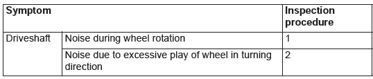
SYMPTOM PROCEDURE
INSPECTION PROCEDURE 1: Noise during Wheel Rotation
DIAGNOSIS
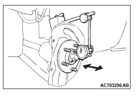
STEP 1. Check the wheel bearing end play.
- Remove the caliper assembly and suspend it with a wire.
- Remove the brake disc from the front hub.
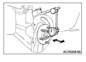
- Attach a dial gauge as shown in the illustration, and then measure the end play while moving the hub in the axial direction.
Limit: 0.05 mm (0.002 inch)
Q: Is the wheel bearing end play within the limit?
YES : Go to step 2.
NO : Replace the part, then go to Step 5.
STEP 2. Check the driveshaft and inner shaft for bending.
Q: Is the driveshaft and inner shaft bent?
YES : Go to step 3.
NO : Replace the part. Then go to Step 5.
STEP 3. Check the center bearing for wear.
Q: Is the center bearing worn?
YES : Replace the bearing. Then go to Step 5.
NO : Go to step 4.
STEP4. Check the driveshaft assembly for wear or damage.
Q: Is the driveshaft assembly worn or damaged?
YES : Replace the driveshaft assembly. Then go to Step 5.
NO : There is no action to be taken.
STEP 5. Retest the system.
Q: Is the abnormal noise eliminated?
YES : The procedure is complete.
NO : Repeat from Step 1.
INSPECTION PROCEDURE 2: Noise Due to Excessive Play of Wheel in Turning Direction
DIAGNOSIS
STEP 1. Check for play in the inner shaft and side gear serration, the driveshaft and side gear serration, or the driveshaft and front hub serration.
Q: Is the play found?
YES : Replace the part. Then go to Step 2.
NO : The procedure is complete.
STEP 2. Retest the system.
Q: Is the abnormal noise eliminated?
YES : The procedure is complete.
NO : Repeat from Step 1.
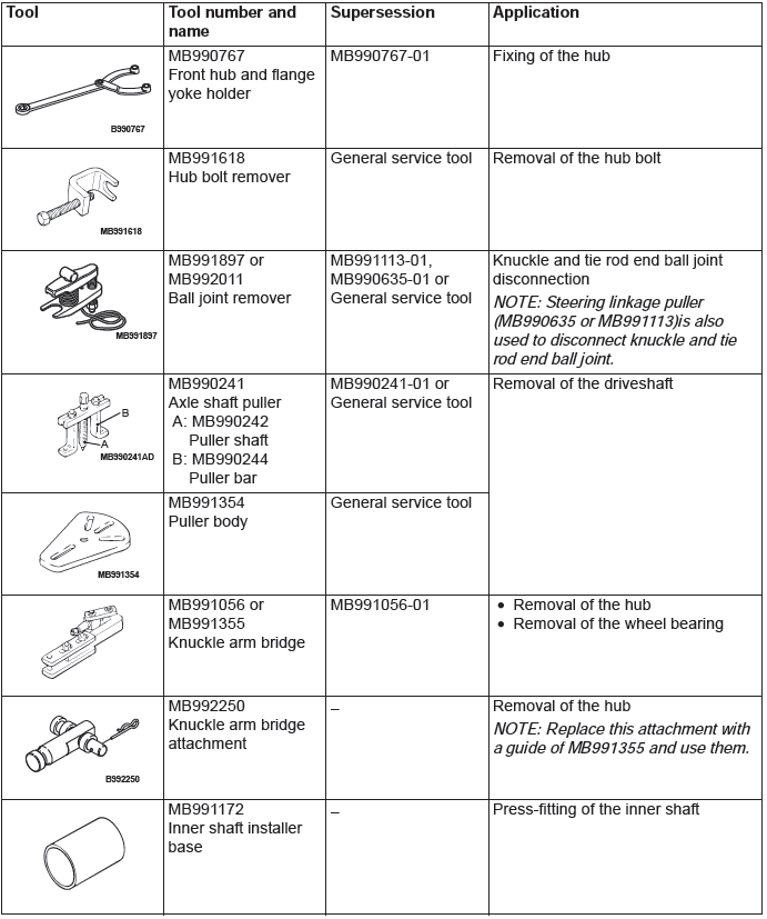
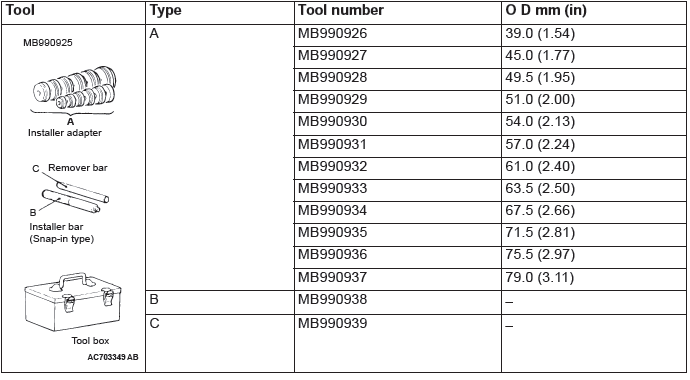
Special Tools
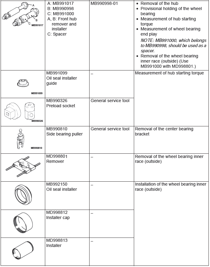
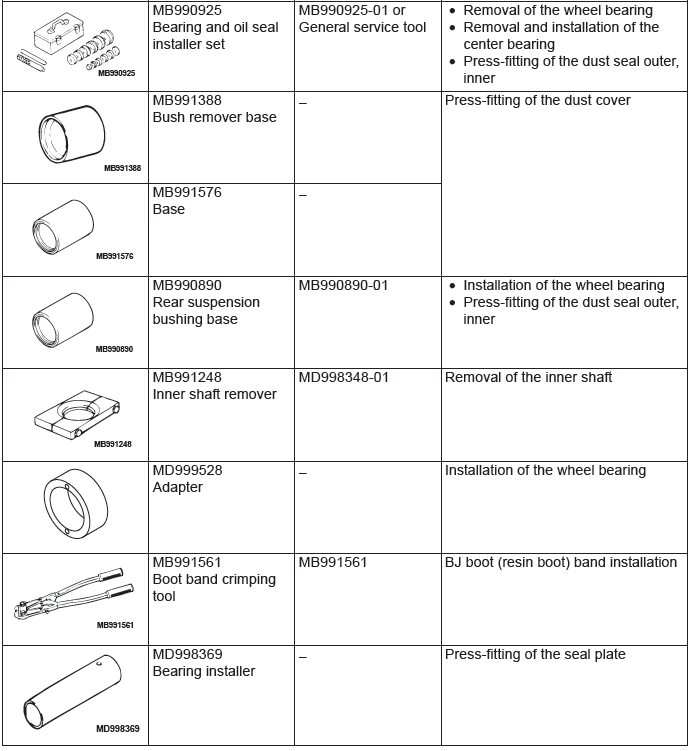
MB990925 BEARING AND OIL SEAL INSTALLER SET
On-vehicle Service
WHEEL BEARING END PLAY CHECK
1. Remove the front caliper assembly and front brake disc, and retain the front caliper assembly with a wire and the like to prevent from falling.
2. Set a dial gauge as shown in the figure. Move the hub in the axial direction and measure the end play.
Limit: 0.05 mm (0.002 inch)
3. If the play exceeds the limit, disassemble hub knuckle to check each component. If the front hub bearing is faulty, replace it.
4. After checking, install the front brake disc and the front caliper assembly.
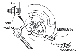
HUB BOLT REPLACEMENT
Required Special Tools:
- MB990767: Front Hub and Flange Yoke Holder
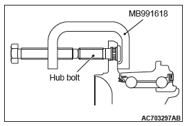
- MB991618: Hub Bolt Remover
1. Remove the front caliper assembly and front brake disc, and retain the front caliper assembly with a wire and the like to prevent from falling.
2. Use special tool MB991618 to remove the hub bolts.
3. Install the plain washer to the new hub bolt, and install the bolt with a nut while holding the hub with special tool MB990767.
4. Install the front brake disc and the front caliper assembly.
READ NEXT:
 Front Axle Hub Assembly
REMOVAL AND INSTALLATION
CAUTION
The magnetic encoder collects metallic particles easily, because it
is magnetized. Make sure that
the magnetic encoder should not collect metallic particles. Che
Driveshaft Assembly
REMOVAL AND INSTALLATION
CAUTION
The magnetic encoder collects metallic particles easily, because it
is magnetized. Make sure that
the magnetic encoder should not collect metallic particles. Che
SEE MORE:
Service Reminder Function Set
HOW TO SET BY OPERATING THE SCAN
TOOL MB991958
CAUTION
If the combination meter needs to be
replaced, the current driving distance and
elapsed days must be entered into the meter
after the replacement in order to be used for
service reminder function. Therefore, read
"Integrated mileage for r
Rear Suspension
General Information
A trailing arm type multi-link suspension is used. The
main features are listed as follows:
The wheel tread is enlarged to improve cornering
ability.
The roll center height is reviewed with regard to
the vehicle specifications to improve the steering
ability.
A double cros
