Mitsubishi Outlander: Rear Suspension
Mitsubishi Outlander 2007-2013 Service Manual / Suspension and Axle / Rear Suspension
General Information
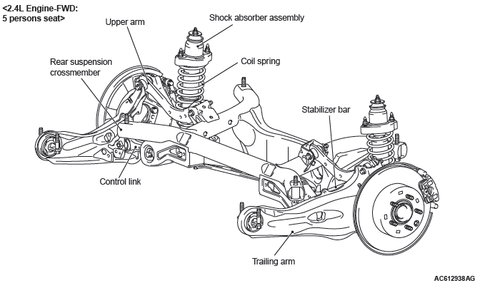
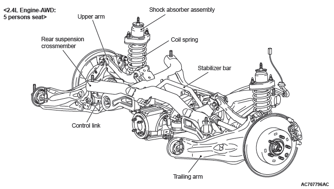
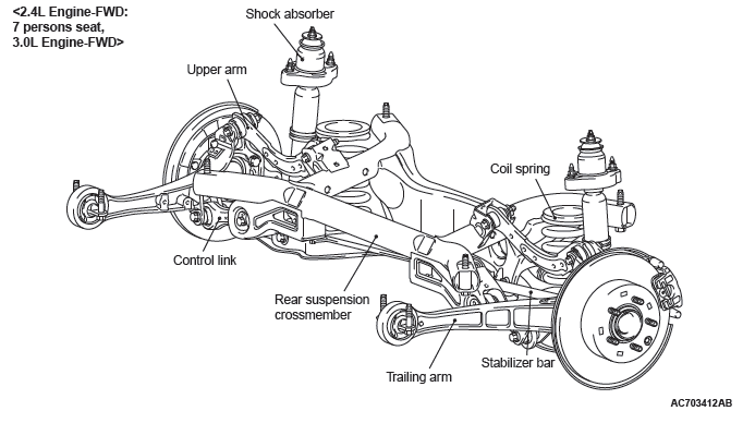
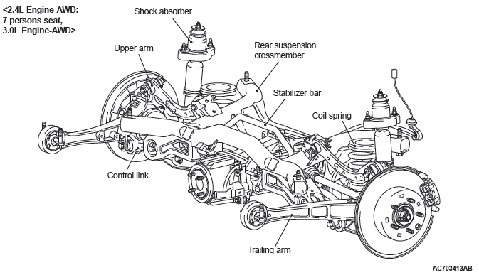
A trailing arm type multi-link suspension is used. The main features are listed as follows:
- The wheel tread is enlarged to improve cornering ability.
- The roll center height is reviewed with regard to the vehicle specifications to improve the steering ability.
- A double crossmember is utilized and the upper arm, lower arm, toe control arm are jointed to the crossmember to improve the suspension alignment accuracy and maintenance performance.
- Improvement of arms installation accuracy eliminates the camber adjustment to improve maintenance performance.
- The trailing arm bushings are installed in the upper position to improve the movement of the suspension when the vehicle negotiates bumps and increase the riding comfort.
- The control link is installed in the lower position to increase the toe and camber rigidity and improve the steering ability.
CONSTRUCTION DIAGRAM
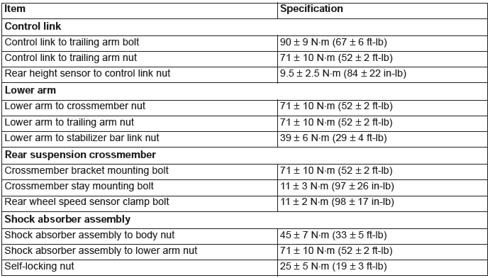
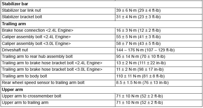
Fastener Tightening Specifications
General Specifications
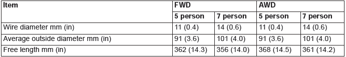
COIL SPRING <2.4L ENGINE>
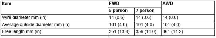
COIL SPRING <3.0L ENGINE>
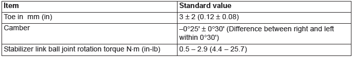
Service Specifications
- Rear Suspension Diagnosis
- Control Link, Upper Arm and Lower Arm
- Trailing Arm Assembly
- Shock Absorber Assembly
- Stabilizer Bar
READ NEXT:
 Rear Suspension Diagnosis
INTRODUCTION TO REAR SUSPENSION DIAGNOSIS
If the rear suspension is faulty, the vehicle will not run
straightforward or noise will occur. Incorrect wheel
alignment, malfunction of shock absorber, stab
Control Link, Upper Arm and Lower Arm
REMOVAL AND INSTALLATION
CAUTION
The parts indicated by *1 should be temporarily tightened, and then
fully tightened with the vehicle
standing on the ground and the curb weight condition.
The p
Trailing Arm Assembly
REMOVAL AND INSTALLATION <2.4L ENGINE: 5 PERSONS SEAT>
CAUTION
The parts indicated by *1 should be temporarily tightened, and then
fully tightened with the vehicle
standing on the ground an
SEE MORE:
Instrument Panel Assembly
Adhesive
NOTE: The symbol in parentheses indicates a part
number.
Special Tool
Instrument Panel Assembly
REMOVAL AND INSTALLATION
The following bolts and screws are used for installing
the instrument panel: The bolts and screws are indicated
by symbols in the illustrations in sections
"REMOVAL AN
Information screen display
Brake warning display
When “RELEASE PARKING BRAKE” is displayed This warning is displayed if you drive
with the parking brake still applied. The warning lamp in the instrument cluster
only illuminates when the parking brake is applied.
CAUTION:
● If a vehicle is driven without rel
© 2010-2026 Copyright www.mioutlander.com
