Mitsubishi Outlander: Propeller Shaft
General Information
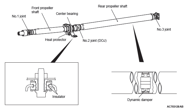
The 2-piece, 3-joint type propeller shaft with a center bearing is adopted.
It has the following features:
- The DOJ, which is of less sliding resistance, is used for the No.2 joint to reduce idling vibration.
- An insulator is installed to the vehicle body joint of the center bearing to reduce vibration.
- The heat protector is adopted to the center bearing bracket.
- Inside the rear propeller shaft, the dynamic damper is integrated to reduce a booming noise caused by the resonance at the high engine speed.
- Adopting the friction welding method, the installation structure is streamlined to reduce weight.
- Lead-free grease is used for the universal joint.
CONSTRUCTION DIAGRAM
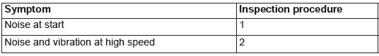
General Specifications
NOTE: *: Indicates the distance between each joint center.
Service Specifications
Lubricant

Propeller Shaft Diagnosis
INTRODUCTION TO PROPELLER SHAFT DIAGNOSIS
If an abnormal noise is heard from the propeller shaft while driving, some parts of the propeller shaft may be worn or damaged, or some mounting bolts may be loose.
PROPELLER SHAFT DIAGNOSTIC TROUBLESHOOTING STRATEGY
Use these steps to plan your diagnostic strategy. If you follow them carefully, you will be sure that you have exhausted all of the possible ways to find a propeller shaft fault.
1. Gather information from the customer.
2. Verify that the condition described by the customer exists.
3. Find the malfunction by following the Symptom Chart.
4. Verify malfunction is eliminated.
SYMPTOM CHART
SYMPTOM PROCEDURES
INSPECTION PROCEDURE 1: Noise at Start
DIAGNOSIS
STEP 1. Check if the propeller shaft mounting nuts and the center bearing mounting nuts are loose.
Q: Are the mounting nuts tightened to the specified torque?
YES : Go to Step 2.
NO : Tighten the propeller shaft mounting nuts to 54 +- 5 N*m (40 +- 3 ft-lb). Tighten the center bearing mounting nuts to 41 +- 5 N*m (30 +- 3 ft-lb). Then go to Step 4.
STEP 2. Check the sleeve yoke's spline of the front propeller shaft for wear.
Q: Is wear apparent? YES : Replace the propeller shaft. Then go to Step 4.
NO : Go to Step 3.
STEP 3. Check the propeller shaft for looseness.
Q: Is looseness recognized?
YES : Replace the propeller shaft. Then go to Step 4.
NO : Go to Step 4.
STEP 4. Retest the system.
Q: Is the abnormal noise eliminated?
YES : The procedure is complete.
NO : Recheck from Step 1.
INSPECTION PROCEDURE 2: Noise and Vibration at High Speed
DIAGNOSIS
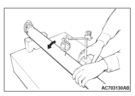
STEP 1. Check the propeller shaft runout.
Q: Is the measured value within the limit; Front :0.5 mm (0.02 inch) or Rear: 0.8 mm (0.03 inch) ? YES : Go to Step 2.
NO : Replace the propeller shaft. Then go to Step 3.
STEP 2. Check the propeller shaft for looseness.
Q: Is looseness recognized?
YES : Replace the propeller shaft. Then go to Step 3.
NO : Go to Step 3.
STEP 3. Retest the system.
Q: Is the abnormal noise eliminated?
YES : The procedure is complete.
NO : Recheck from Step1.
Special Tool
On-vehicle Service
PROPELLER SHAFT UNIVERSAL JOINT CHECK
PROPELLER SHAFT VISUAL CHECK
1. Place the selector lever to the "N" position.
2. Then place the drive mode selector to the "2WD" position.
3. Check the propeller shaft for dent, damage or crack.
4. Check the propeller shaft universal joint, oil seal for crack or damage. If abnormality is recognized, replace the propeller shaft with a new one.
PROPELLER SHAFT UNIVERSAL JOINT PLAY CHECK
1. Place the selector lever to the "N" position.
2. Then place the drive mode selector to the "2WD" position.
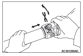
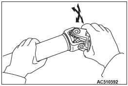
3. Hold the tube of propeller shaft by one hand, and apply force by the other hand to the flange yoke or sleeve yoke in rotating direction, axial direction, and perpendicular direction for checking looseness. If looseness is recognized, replace the propeller shaft with a new one.
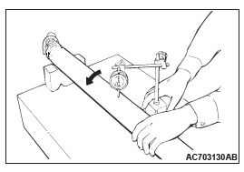
PROPELLER SHAFT UNIVERSAL JOINT FLECTION CHECK
1. Place the selector lever to the "N" position.
2. Then place the drive mode selector to the "2WD" position.
3. Make phase alignment marks on the flange yoke and differential companion flange and disconnect the flange yoke.
4. Hold the tube of propeller shaft by one hand, and apply force by the other hand to the flange yoke in flection direction for checking flection. If showing a sign of catch in the flection direction is recognized, replace the propeller shaft with a new one.
Propeller Shaft
REMOVAL AND INSTALLATION
Pre-removal and Post-installation operation
- Engine Room Under Cover Removal and Installation
- Transfer Oil Draining and Filling
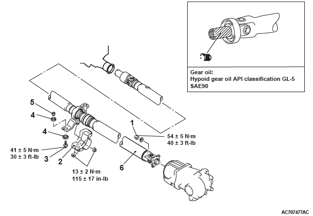
Removal steps
- Flange yoke and electronic control coupling connecting nut
- Heat protector
- Bolt
- Insulator
- Spacer
- Propeller shaft assembly
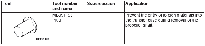
Required Special Tool:
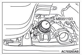
- MB991193: Plug
REMOVAL SERVICE POINT
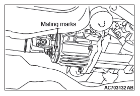
FLANGE YOKE AND ELECTRONIC CONTROL COUPLING CONNECTING NUT REMOVAL
1. Put mating marks on the flange yoke and the electronic control coupling.
PROPELLER SHAFT ASSEMBLY REMOVAL
CAUTION If the joint assembly is bent, it may be damaged when pinching the joint boots.
1. Insert a waste or similar materials into the joint boots, and remove the propeller shaft assembly by aligning the front propeller shaft with the rear shaft.
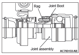
2. Using special MB991193, cover the transfer case to prevent the entry of foreign materials.
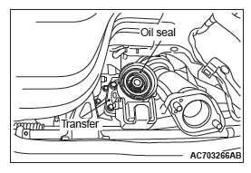
INSTALLATION SERVICE POINT
PROPELLER SHAFT ASSEMBLY INSTALLATION
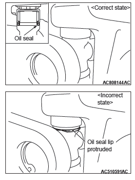
CAUTION
- Do not damage the oil seal lip of the transfer.
- The mounting bolt and nut may be loosened if oil or
grease is stuck on the threads of the bolt and nut.
Tighten them after degreasing the threads.
- If the joint assembly is bent, it may be damaged when pinching the joint boots.
FLANGE YOKE AND ELECTRONIC CONTROL COUPLING CONNECTING NUT INSTALLATION
If the propeller shaft is reused, align the mating marks and install the connecting nuts.
Tightening torque: 54 +- 5 N*m (40 +- 3 ft-lb)
INSPECTION
PROPELLER SHAFT RUNOUT
Limit
- Front: 0.5 mm (0.02 inch)
- Rear: 0.8 mm (0.03 inch)
READ NEXT:
 Wheel and Tire
Specifications
The wheels and tires of the following specifications
have been established.
SPECIFICATIONS
ROAD WHEEL AND TIRE
<EXCEPT FOR CANADA>
<VEHICLES FOR CANADA>
SPARE WHEEL AND TI
Power Plant Mount
General Information
For the power plant support, the inertial axis
four-point mounting system is utilized, and the system
has the following features.
For the engine and transaxle mountings, the
cyl
SEE MORE:
Camshaft
REMOVAL AND INSTALLATION
Removal steps
Engine oil control valve (OCV)
exhaust
O-ring
Engine oil control valve (OCV)
intake
O-ring
Front camshaft bearing cap
Oil feeding camshaft bearing cap
Camshaft bearing cap
Thrust camshaft bearing cap
Bearing
Camshaft intake
Camshaft exhaust
Bear
How To Diagnose (Electrical)
HOW TO DIAGNOSE
The most important point in troubleshooting is to
determine "Probable Cause". Once the probable
causes are determined, parts to be checked can be
limited to those associated with such probable
causes. The determination of the probable causes
must be based on a theory and be supported
