Mitsubishi Outlander: Differential
DISASSEMBLY AND ASSEMBLY
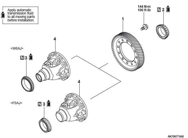
Disassembly Steps
- Final gear
- Differential side bearing (transmission case side)
- Differential side bearing (converter housing side)
- Differential sub-assembly
Required special tools:
- MB990801: Real axle bearing puller
- MB990811: Side bearing puller cap
- MB990956: Needle bearing installer
- MB990810: Side bearing puller
- MD999566: Claw
- MD998761: Cam oil seal installer
- MD998812: Installer cap
- MD998813: Installer-100
- MD998826: Installer adapter
- MB991559: Cam oil seal installer adapter
- MB992213: Bearing installer
- MB992150: Oil seal installer
DISASSEMBLY SERVICE POINT
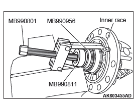
DIFFERENTIAL SIDE BEARING REMOVAL
1. Break and remove the roller of the differential side bearing.
2. Using the special tools MB990801, MB990811 and MB990956, remove the inner race of differential side bearing (transmission case side) from the differential sub-assembly.
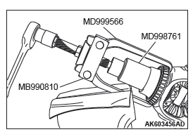
DIFFERENTIAL SIDE BEARING REMOVAL
1. Using the special tools MB990810, MD999566 and MD998761, remove the inner race of differential side bearing (converter housing side) from the differential sub-assembly.
ASSEMBLY SERVICE POINT
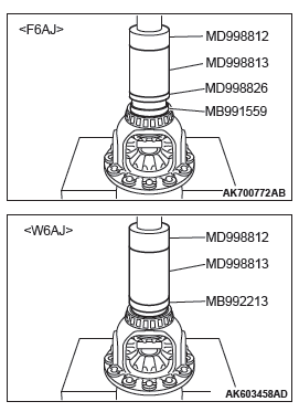
DIFFERENTIAL SIDE BEARING INSTALLATION
CAUTION
- Do not re-use the inner race.
- Replace the inner race together with the outer race.
Using the special tools MD998812, MD998813, MD998826 <F6AJ> and MB991559 <F6AJ> or MB992213 <W6AJ>, install the differential side bearing (converter housing side) on the differential sub-assembly.
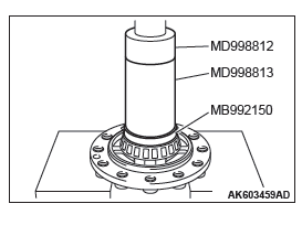
DIFFERENTIAL SIDE BEARING INSTALLATION
CAUTION
- Do not re-use the inner race.
- Replace the inner race together with the outer race.
Using the special tools MD998812, MD998813 and MB992150, install the inner race of differential side bearing (transmission case side) on the differential sub-assembly.
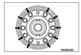
FINAL GEAR INSTALLTION
CAUTION
- The differential sub-assembly can be only assembled, but not disassembled.
- Assemble the final gear to the differential assembly in the chamfer direction in the inside diameter of the final gear.
- Tighten bolts diagonally.
Install the final gear on the differential assembly. Refer to the following or the exploded view for the tightening torque.

Tightening torque: 144 N*m (106 ft-lb)
READ NEXT:
 Transfer
DISASSEMBLY AND ASSEMBLY
<Vehicles with S-AWC>
Disassembly steps
Dust seal guard
Oil seal
O-ring
Dust seal
Oil seal
Cover
Transfer
<Vehicles without S-AWC>
Disassembly steps
Propeller Shaft
General Information
The 2-piece, 3-joint type propeller shaft with a center
bearing is adopted.
It has the following features:
The DOJ, which is of less sliding resistance, is
used for the No.2 jo
Wheel and Tire
Specifications
The wheels and tires of the following specifications
have been established.
SPECIFICATIONS
ROAD WHEEL AND TIRE
<EXCEPT FOR CANADA>
<VEHICLES FOR CANADA>
SPARE WHEEL AND TI
SEE MORE:
Check Procedure For Each Multi Information Display Screen
CHECK PROCEDURE FOR EACH MULTI INFORMATION DISPLAY SCREEN
<VEHICLES WITHOUT COLOR LIQUID CRYSTAL DISPLAY>
CAUTION
When there are TV towers, substations, or broadcasting
stations which emit strong radio waves
in proximity, on rare occasions, a warning is displayed
on the multi information scree
DTC B1000, B1003, B1018, B1021, B1031, B1032, B1034, B1035, B1079,
B2214, B223B
DTC B1000: Control Panel Communication Error
DTC SET CONDITION
DTC B1000 will be set when the communication
between A/C-ECU and A/C control panel cannot be
performed.
TECHNICAL DESCRIPTION (COMMENT)
Current trouble
The A/C-ECU, the A/C control panel, or connector(
s) or wiring between the two m
