Mitsubishi Outlander: KOS-ECU, Keyless Operation Key, TPMS Transmitter
KOS-ECU
REMOVAL AND INSTALLATION
CAUTION If KOS-ECU is replaced, refer to ID code registration need judgment table P.42B to complete the registration of each ID code.
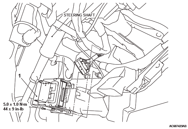
Removal
- KOS-ECU
Exterior Transmitter Antenna Assembly, Interior Transmitter Antenna Assembly, Receiver Antenna Module
REMOVAL AND INSTALLATION
<EXTERIOR TRANSMITTER ANTENNA ASSEMBLY, INTERIOR TRANSMITTER ANTENNA ASSEMBLY, ANTENNA AND BUZZER ASSEMBLY>
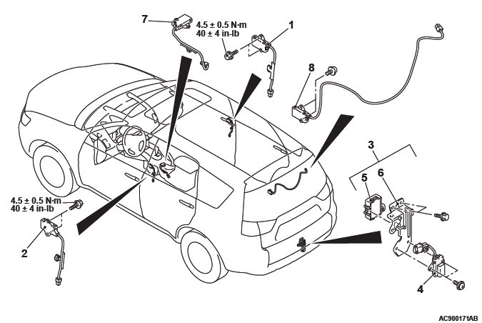
Exterior transmitter antenna assembly (front passenger's side) removal steps
- Center pillar trim, upper <RH>
- Exterior transmitter antenna assembly (front: passenger's side)
Exterior transmitter antenna assembly (driver's side) removal steps
- Center pillar trim, upper <LH>
- Exterior transmitter antenna assembly (driver's side)
Antenna and outer tone alarm assembly removal steps
- Rear bumper assembly
- Antenna and outer tone alarm assembly
- Exterior transmitter antenna assembly (liftgate)
- Outer tone alarm
- Bracket
Interior transmitter antenna assembly (front) removal steps
- Rear floor console assembly
- Interior transmitter antenna assembly (front)
Interior transmitter antenna assembly (rear: RH) removal steps
- Quarter trim, lower <RH>
- Interior transmitter antenna assembly (rear: RH)
<RECEIVER ANTENNA MODULE>
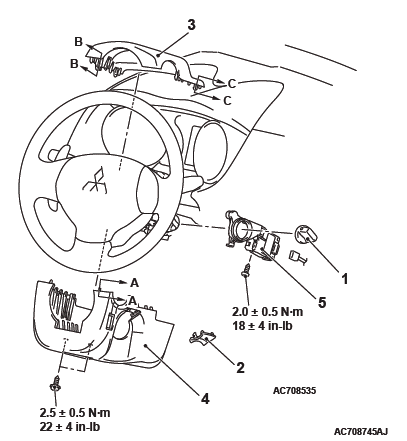
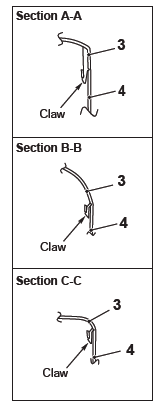
NOTE: Claw position is symmetrical
Receiver antenna module removal
- IG knob cap
- Ignition key cover
- Steering column upper cover
- Steering column lower cover
- Receiver antenna module
INSTALLATION SERVICE POINT
RECEIVER ANTENNA MODULE INSTALLATION
Check that the top claw of receiver antenna module is fixed securely to the boss of steering lock and the antenna is not floated on the key cylinder.
Keyless Operation Key
DISASSEMBLY AND ASSEMBLY
Post-installation operation
Operation check of the keyless operation key
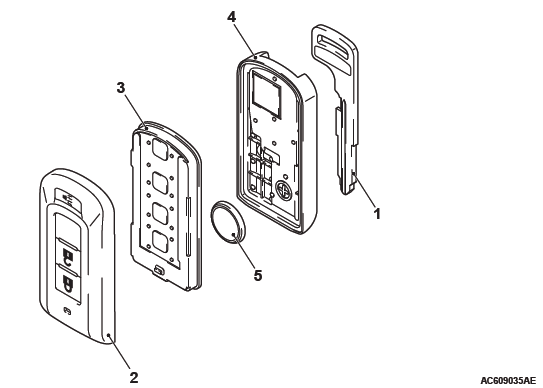
Disassembly steps
- Emergency key
- Upper cover
- Transmitter assembly
- Lower cover
- Battery
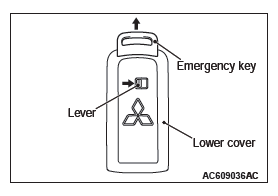
DISASSEMBLY SERVICE POINTS
EMERGENCY KEY REMOVAL
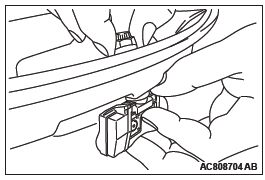
Move the lever on the lower cover to the direction shown by the arrow to remove the emergency key from the keyless operation key.
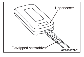
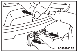
UPPER COVER REMOVAL
CAUTION Do not allow water or dust to enter the inside of the transmitter assembly when it is open. Also, do not touch the precision electronic device.
Set a flat-tipped screwdriver wrapped with protective tape as shown in the figure, and pry off the keyless operation key.
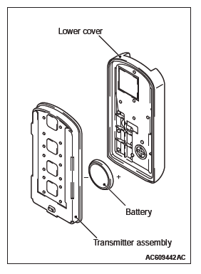
ASSEMBLY SERVICE POINT
BATTERY INSTALLATION
CAUTION Do not allow water or dust to enter the inside of the transmitter assembly when it is open. Also, do not touch the precision electronic device.
Install a battery with the positive side facing toward the lower cover.
Replacement battery: Coin-type lithium battery CR2032
TPMS Transmitter
REMOVAL AND INSTALLATION
WARNING Certain components of this vehicles, such as TPMS transmitters, may contain perchlorate materials. Special handling may apply. For additional information, see www.dtsc.ca.gov/hazardouswaste/ perchlorate.
CAUTION
- Do not vary the angle of valve except at mounting on the rim.
- Ensure valve cap is always in place except when adjusting tire pressure.
- If the valve core and valve cap are replaced, use a genuine replacement part. The valve core is similar to a conventional one, but uses nickel plating to avoid corrosion.
- Replace the seal washer with a new one every five years or when the tire is replaced.
- Do not drop the TPMS transmitter from height greater than 1 meter (3.3 feet).
- Do not expose the TPMS transmitter to extraneous magnetic fields.
- TPMS transmitter should not be stored at temperatures above 80ºC (176ºF).
- TPMS transmitter should not be exposed to temperatures above 100ºC (212ºF).
- If the TPMS transmitter is replaced, execute "Tire Pressure Sensor ID Registration" on scan tool MB991958 "Special Function".
- Be careful not to damage the TPMS transmitter.
Pre-removal Operation
- Wheel and Tire Removal
Post-installation Operation
- Wheel and Tire Installation
- Tire Pressure Sensor ID Registration If a new TPMS transmitter is installed
- After the tire pressure sensor ID registration, check that the TPMS warning light does not illuminate or flash
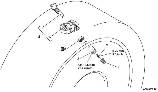
Removal steps
- Cap
- Valve core
- Nut
- Let TPMS transmitter fall into tire
- Tire bead
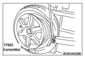
- TPMS transmitter
- Seal washer
- Housing <In case of removing the valve>
- Valve <In case of removing the valve>
Installation steps
- Valve <In case of installing the valve>
- Housing <In case of installing the valve>
- Seal washer
- TPMS transmitter
- Nut
- Tire bead mounting
- Valve core
- Tire pressure inflation
- Valve nut retightening
- Cap
REMOVAL SERVICE POINTS
CAP/VALVE CORE/NUT REMOVAL
CAUTION Ensure cap is always in place except when adjusting tire pressure.
1. Remove the valve cap.
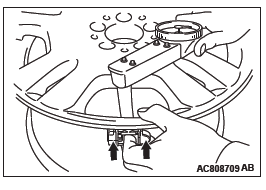
2. Rotate tire so that valve stem is in the 6 o'clock position.
3. Use a long-reach 17.2 mm (0.68 inch) socket to unscrew the valve nut a few turns. Slowly push valve stem into tire so that tire pressure is relieved.
4. Once tire pressure is released, remove nut and let TPMS transmitter fall into tire.
TPMS TRANSMITTER REMOVAL
CAUTION Be careful not to damage the TPMS transmitter.
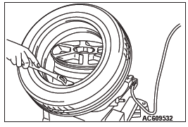
1. Place on tire changing machine and break both tire beads ensuring that the TPMS transmitter remains in the bottom of the tire.
2. Lubricate tire well and remove outer side of the tire.
3. Reach inside the tire and remove the TPMS transmitter.
4. Remove tire from rim using proper tire changing equipment procedures.
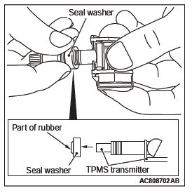
SEAL WASHER/VALVE REMOVAL
CAUTION Remove the seal washer to prevent scratching the valve of the TPMS transmitter.
1. Hold the TPMS transmitter and the seal washer, then extract the seal washer. Take care to not damage the valve thread.
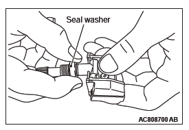
2. Clean the TPMS transmitter and the valve stem. <In case of not removing the valve>
NOTE: If the valve comes out from transmitter, install it to where it was. (This is not failure)
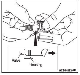
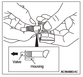
3. Removal the valve from housing as shown.
INSTALLATION SERVICE POINTS
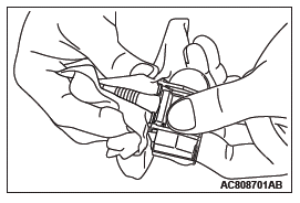
VALVE/SEAL WASHER/TPMS TRANSMITTER/ NUT INSTALLATION
CAUTION Install the seal washer to prevent scratching the valve of the TPMS transmitter.
1. Install the valve to housing as shown.
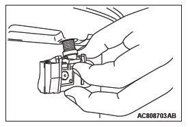
2. Insert the seal washer up to the base of the TPMS transmitter, making sure to secure the valve base with a thumb as shown.
Wipe the seal and threading.
CAUTION
- Visually check that TPMS transmitter is not deformed or damaged.
- When installing the TPMS transmitter, be sure the rim, seal valve and nut are clean.
- Ensure the grommet is located inside the valve hole before installing the nut.
- While installing the nut, push the TPMS transmitter to maintain the lower lip of the transmitter case is in contact with the rim without clearance.
- While installing the valve nut, ensure the tool is kept aligned to the valve and the valve hole.
3. Install the valve, in the valve hole, without modifying the angle of the stem (retain position of delivery). The laser marking should be visible at the operator.
4. When the valve is completely inserted, maintain the TPMS transmitter in contact with the rim, then screw manually the nut until the contact with the wheel.
5. While maintaining the TPMS transmitter contact with the rim by applying pressure to the back of the valve, slightly press on the cap to wards the center of the wheel in order to adapt the angle of the valve/TPMS transmitter to the profile of the rim.
It is mandatory to guarantee the contact of the housing unit on the rim drop center.
6. While maintaining the TPMS transmitter and valve in position, screw the nut with a torque wrench.
Take care that the wrench socket is correctly inserted on the nut.
Specified torque: 8.0 +- 0.5 N*m (71 +- 4 in-lb)
TIRE BEAD MOUNTING
1. Prepare the tire and fix the rim as usual.
2. Put the tire on the rim, so that the cross point of the belt with the rim is approximately 20 cm (7.9 inch) away from the valve.
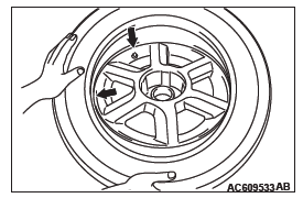
3. Engage the shoe and make sure that 20 cm (7.9 inch) is maintained between the cross point and the valve.
The arrow shows the direction of rotation of the wheel.
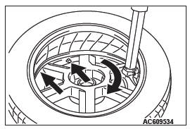
4. Turn the wheel in order to engage all the first side of the tire.
NOTE: The standard shoes can pass over the sensor without damaging it.
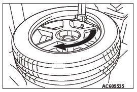
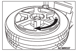
5. Put the second side of the tire in position, so that the cross point of the belt with the rim is approximately 20 cm (7.9 inch) away from the valve. The curved arrow shows the direction of rotation of the wheel.
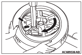
6. Turn the wheel in order to engage all of the second side of the tire.
NOTE: The standard shoes can pass over the sensor without damaging it.
TIRE PRESSURE INFLATION/NUT RETIGHTENING
CAUTION After tire inflation, retighten the valve nut to 8.0 +- 0.5 N*m (71 +- 4 in-lb). This is necessary, because the TPMS transmitter is secured to the wheel with the valve nut and rubber grommet. The rubber grommet will be depressed by tire pressure or deteriorate over a period of time, which requires the valve nut to be retightened.
Inflate tire to required pressure, then retorque the valve nut to 8.0 +- 0.5 N*m (71 +- 4 in-lb).
READ NEXT:
 Wireless Control Module (WCM)
General Information
The wireless control module (WCM) is a system that
integrates the keyless entry function, with which
remote operation (opening/closing of all doors and
the liftgate and operation o
Diagnosis
STANDARD FLOW OF DIAGNOSTIC
TROUBLESHOOTING
Refer to GROUP 00 − How to Use Troubleshooting/Inspection
Service Points, Contents of Troubleshooting.
DIAGNOSTIC FUNCTION
HOW TO CONNECT THE SCAN TO
DTC B1731, B1761, B1A08, B1A09, B1A0A, B1A0B, B1A0C, B1A0D, B1A0E, B1A0F,
B1A10, B1A11, B1A12, B1A13, B1A14, B1A15, B1A16, B1A17, B1A24, B1A25, B1A28,
B1A35, B2101, B2102
DTC B1731: Engine control module communication timeout
CAUTION
When the DTC B1731 is set, be sure to diagnose
the CAN bus line.
When replacing the ECU, always check that
the communication circuit
SEE MORE:
On-vehicle Service
WHEEL SPEED SENSOR OUTPUT CURRENT
MEASUREMENT
Required Special Tools:
MB991709: Wiring harness set
The relevant wheel, on which the wheel speed sensor is fitted,
should be free to run.
1. Remove the wheel speed sensor connector to be checked.
CAUTION
For precise measurement, do not connect to th
Central door locks
Vehicles without the keyless entry system and vehicles without the keyless
operation system
Using the key on driver’s door locks or unlocks driver’s doors and the tailgate.
1- Lock.
2- Unlock.
NOTE:
● If the vehicle has a Dead Lock System and the Dead Lock System is set, turning
