Mitsubishi Outlander: DTC B1731, B1761, B1A08, B1A09, B1A0A, B1A0B, B1A0C, B1A0D, B1A0E, B1A0F, B1A10, B1A11, B1A12, B1A13, B1A14, B1A15, B1A16, B1A17, B1A24, B1A25, B1A28, B1A35, B2101, B2102
DTC B1731: Engine control module communication timeout
CAUTION
- When the DTC B1731 is set, be sure to diagnose the CAN bus line.
- When replacing the ECU, always check that the communication circuit is normal.
DTC SET CONDITION
WCM checks that the engine control module data has been received via the CAN bus lines, and if not, sets the DTC No. B1731.
TECHNICAL DESCRIPTION (COMMENT)
If no data [ETACS transmits engine random number data to WCM via the CAN bus lines] is received from the engine control module via the CAN bus lines when the ignition switch is turned to ON position, it is judged as abnormal.
TROUBLESHOOTING HINTS
- Malfunction of CAN bus line
- Malfunction of WCM
- Malfunction of engine control module
- Malfunction of ETACS-ECU
DIAGNOSIS
Required Special Tools:
- MB991958: Scan Tool (M.U.T.-III Sub Assembly)
- MB991824: Vehicle Communication Interface (V.C.I.)
- MB991827: M.U.T.-III USB Cable
- MB991910: M.U.T.-III Main Harness A (Vehicles with CAN communication system)
STEP 1. Using scan tool MB991958, diagnose the CAN bus line.
CAUTION To prevent damage to scan tool (MB991958), always turn the ignition switch to the "LOCK" (OFF) position before connecting or disconnecting scan tool (MB991958).
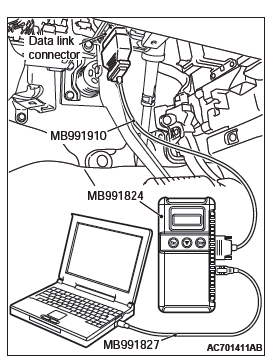
- Connect scan tool MB991958 to the data link connector.
- Turn the ignition switch to the "ON" position.
- Diagnose the CAN bus line.
- Turn the ignition switch to the "LOCK" (OFF) position.
Q: Is the CAN bus line found to be normal?
YES : Go to Step 2.
NO : Repair the CAN bus line. On completion, go to Step 2.
STEP 2. Using scan tool MB991958, read the engine control module diagnostic trouble code.
Check again if the DTC is set to the engine control module.
Q: Is the DTC set?
YES : Troubleshoot the MFI system.
NO : Go to Step 3.
STEP 3. Using scan tool MB991958, read the other system diagnostic trouble code.
Check if DTC U0100 is set to ETACS-ECU.
Q: Is the DTC set?
YES : Go to Step 5.
NO : Go to Step 4.
STEP 4. Recheck for diagnostic trouble code.
Check again if the DTC is set to the WCM.
- Turn the ignition switch from "LOCK" (OFF) position to "ON" position.
- Check if DTC is set.
- Turn the ignition switch to the "LOCK" (OFF) position.
Q: Is the DTC set?
YES : Replace WCM and register the ID codes. After registering the ID codes, go to Step 6.
NO : The trouble can be an intermittent malfunction.
STEP 5. Recheck for diagnostic trouble code.
Check again if the DTC is set to the WCM.
- Turn the ignition switch from "LOCK" (OFF) position to "ON" position.
- Check if DTC is set.
- Turn the ignition switch to the "LOCK" (OFF) position.
Q: Is the DTC set?
YES : Replace the engine control module and record the VIN. Then go to Step 6.
NO : The procedure is complete.
STEP 6. Recheck for diagnostic trouble code.
Check again if the DTC is set to the WCM.
- Turn the ignition switch from "LOCK" (OFF) position to "ON" position.
- Check if DTC is set.
- Turn the ignition switch to the "LOCK" (OFF) position.
Q: Is the DTC set?
YES : Replace the ETACS-ECU.
NO : The procedure is complete.
DTC B1761: VIN code not programmed
CAUTION
- When the DTC No. B1761 is set, be sure to diagnose the CAN bus line.
- When replacing the ECU, always check that the communication circuit is normal.
DTC SET CONDITION
WCM sets DTC B1761 when no VIN is recorded in it.
TECHNICAL DESCRIPTION (COMMENT)
WCM determines that the abnormality is present when no VIN is recorded in it.
TROUBLESHOOTING HINTS
- VIN not programmed
- Malfunction of the WCM
DIAGNOSIS
Required Special Tools:
- MB991958: Scan Tool (M.U.T.-III Sub Assembly)
- MB991824: Vehicle Communication Interface (V.C.I.)
- MB991827: M.U.T.-III USB Cable
- MB991910: M.U.T.-III Main Harness A (Vehicles with CAN communication system)
STEP 1. Using scan tool MB991958, diagnose the CAN bus line.
CAUTION To prevent damage to scan tool (MB991958), always turn the ignition switch to the "LOCK" (OFF) position before connecting or disconnecting scan tool (MB991958).

- Connect scan tool MB991958 to the data link connector.
- Turn the ignition switch to the "ON" position.
- Diagnose the CAN bus line.
- Turn the ignition switch to the "LOCK" (OFF) position.
Q: Is the CAN bus line found to be normal?
YES : Go to Step 2.
NO : Repair the CAN bus line.
STEP 2. Register the VIN and recheck the diagnostic trouble code.
Register VIN in WCM (Refer to GROUP 00 − How to Perform Vehicle Identification Number (VIN) Writing) and recheck if the DTC is set.
- Turn the ignition switch from the "LOCK" (OFF) position to the "ON" position.
- Check if DTC is set.
- Turn the ignition switch to the "LOCK" (OFF) position.
Q: Is the DTC set?
YES : Replace WCM and register the ID codes. NO : The procedure is complete.
DTC B1A08: Keyless/KOS key1 performance
DTC B1A09: Keyless/KOS key2 performance
DTC B1A0A: Keyless/KOS key3 performance
DTC B1A0B: Keyless/KOS key4 performance
DTC B1A0C: Keyless key 5 performance
DTC B1A0D: Keyless key 6 performance
DTC B1A0E: Keyless key 7 performance
DTC B1A0F: Keyless key 8 performance
CAUTION When replacing the ECU, always check that the communication circuit is normal.
DTC SET CONDITION
The door locking/unlocking code is automatically updated every time the doors are locked (rolling code). WCM stores DTC B1A08, B1A09, B1A0A, B1A0B, B1A0C, B1A0D, B1A0E, or B1A0F when it receives wrong signal (rolling code out of synchronization) from the transmitter.
TECHNICAL DESCRIPTION (COMMENT)
- B1A08: WCM determines that the abnormality is present when the rolling code received from the transmitter 1 (the first transmitter registered in WCM) greatly differs from the rolling code stored in WCM.
- B1A09: WCM determines that the abnormality is present when the rolling code received from the transmitter 2 (the second transmitter registered in WCM) greatly differs from the rolling code stored in WCM.
- B1A0A: WCM determines that the abnormality is present when the rolling code received from the transmitter 3 (the third transmitter registered in WCM) greatly differs from the rolling code stored in WCM.
- B1A0B: WCM determines that the abnormality is present when the rolling code received from the transmitter 4 (the fourth transmitter registered in WCM) greatly differs from the rolling code stored in WCM.
- B1A0C: WCM determines that the abnormality is present when the rolling code received from the transmitter 5 (the fifth transmitter registered in WCM) greatly differs from the rolling code stored in WCM.
- B1A0D: WCM determines that the abnormality is present when the rolling code received from the transmitter 6 (the sixth transmitter registered in WCM) greatly differs from the rolling code stored in WCM.
- B1A0E: WCM determines that the abnormality is present when the rolling code received from the transmitter 7 (the seventh transmitter registered in WCM) greatly differs from the rolling code stored in WCM.
- B1A0F: WCM determines that the abnormality is present when the rolling code received from the transmitter 8 (the eighth transmitter registered in WCM) greatly differs from the rolling code stored in WCM.
TROUBLESHOOTING HINTS
- Rolling code out of synchronization
- Malfunction of the transmitter
- Malfunction of the WCM
DIAGNOSIS
STEP 1. Synchronize the rolling code and recheck the diagnostic trouble code.
- Synchronize the rolling code.
- Push the lock button or unlock button of transmitter twice or more.
- If the keyless operation does not resume by the procedure above, register the key again.
- Recheck if the diagnostic trouble code is set.
- Push the lock button or unlock button of transmitter.
- Check if the diagnostic trouble code is set.
Q: Is the DTC set?
YES : Go to Step 2.
NO : The diagnosis is complete.
STEP 2. Check whether the diagnostic trouble code is reset.
Replace the transmitter by which the diagnostic trouble code is set with a new one, register the key, and recheck if the diagnostic trouble code is set.
- Push the lock button or unlock button of transmitter.
- Check if the diagnostic trouble code is set.
Q: Is the DTC set?
YES : Replace WCM and register the ID codes.
NO : The diagnosis is complete.
Code No.B1A10 Keyless/KOS key 1 low battery
Code No.B1A11 Keyless/KOS key 2 low battery
Code No.B1A12 Keyless/KOS key 3 low battery
Code No.B1A13 Keyless/KOS key 4 low battery
Code No.B1A14 Keyless key 5 low battery
Code No.B1A15 Keyless key 6 low battery
Code No.B1A16 Keyless key 7 low battery
Code No.B1A17 Keyless key 8 low battery
CAUTION When replacing the ECU, always check that the communication circuit is normal.
DIAGNOSTIC FUNCTION
WCM sets the diagnostic trouble code No. B1A10, B1A11, B1A12, B1A13, B1A14, B1A15, B1A16, or B1A17 when it receives low battery voltage signal from the transmitter.
JUDGEMENT CRITERIA
- B1A10: WCM determines that the abnormality is present when it receives low battery voltage signal from the transmitter 1 (the first transmitter registered in WCM) five consecutive times.
- B1A11: WCM determines that the abnormality is present when it receives low battery voltage signal from the transmitter 2 (the second transmitter registered in WCM) five consecutive times.
- B1A12: WCM determines that the abnormality is present when it receives low battery voltage signal from the transmitter 3 (the third transmitter registered in WCM) five consecutive times.
- B1A13: WCM determines that the abnormality is present when it receives low battery voltage signal from the transmitter 4 (the fourth transmitter registered in WCM) five consecutive times.
- B1A14: WCM determines that the abnormality is present when it receives low battery voltage signal from the transmitter 5 (the fifth transmitter registered in WCM) five consecutive times.
- B1A15: WCM determines that the abnormality is present when it receives low battery voltage signal from the transmitter 6 (the sixth transmitter registered in WCM) five consecutive times.
- B1A16: WCM determines that the abnormality is present when it receives low battery voltage signal from the transmitter 7 (the seventh transmitter registered in WCM) five consecutive times.
- B1A17: WCM determines that the abnormality is present when it receives low battery voltage signal from the transmitter 8 (the eighth transmitter registered in WCM) five consecutive times.
PROBABLE CAUSES
- Battery failure in the transmitter
- Malfunction of the transmitter
- Malfunction of WCM
DIAGNOSTIC PROCEDURE
STEP 1. Replace the battery in the transmitter and recheck the diagnostic trouble code.
Replace the battery in the transmitter with a new one, and recheck if the diagnostic trouble code is set.
- Replace the battery in the transmitter.
- Use the transmitter to lock/unlock the doors.
- Check if the diagnostic trouble code is set.
Q: Is the diagnostic trouble code set?
YES : Go to Step 2.
NO : The procedure is complete. (Discharged battery)
STEP 2. Replace the transmitter and recheck the diagnostic trouble code.
Replace the transmitter with a new one, register the encrypted code and the keyless entry secret code, and recheck if the diagnostic trouble code is set.
- Use the transmitter to lock/unlock the doors.
- Check if the diagnostic trouble code is set.
Q: Is the diagnostic trouble code set?
YES : Replace WCM and register the ID codes.
NO : The procedure is complete.
DTC B1A24: Key ID not registered
CAUTION
- When the DTC B1A24 is set, be sure to diagnose the CAN bus line.
- When replacing the ECU, always check that the communication circuit is normal.
DTC SET CONDITION
WCM sets DTC B1A24 when the encrypted code was not registered in it.
TECHNICAL DESCRIPTION (COMMENT)
WCM determines that the abnormality is present, if the ignition key's key ID is not registered in WCM when the ignition switch is turned ON.
TROUBLESHOOTING HINTS
- Key ID not registered
- Malfunction of the ignition key
- Malfunction of WCM
DIAGNOSIS
Required Special Tools:
- MB991958: Scan Tool (M.U.T.-III Sub Assembly)
- MB991824: Vehicle Communication Interface (V.C.I.)
- MB991827: M.U.T.-III USB Cable
- MB991910: M.U.T.-III Main Harness A (Vehicles with CAN communication system)
STEP 1. Using scan tool MB991958, diagnose the CAN bus line.
CAUTION To prevent damage to scan tool (MB991958), always turn the ignition switch to the "LOCK" (OFF) position before connecting or disconnecting scan tool (MB991958).
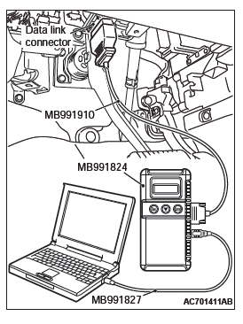
- Connect scan tool MB991958 to the data link connector.
- Turn the ignition switch to the "ON" position.
- Diagnose the CAN bus line.
- Turn the ignition switch to the "LOCK" (OFF) position.
Q: Is the CAN bus line found to be normal?
YES : Go to Step 2.
NO : Repair the CAN bus line.
TEP 2. Register the key ID and recheck the diagnostic trouble code.
Register the key ID of the ignition key, and recheck if the DTC is set.
- Turn the ignition switch from the "LOCK" (OFF) position to the "ON" position.
- Check if the DTC is set.
Q: Is the DTC set?
YES : Replace WCM and register the ID codes. NO : The procedure is complete.
DTC B1A25: Key ID unmatched
CAUTION When the DTC B1A25 is set, be sure to diagnose the CAN bus line.When replacing the ECU, always check that the communication circuit is normal.
DTC SET CONDITION
WCM sets DTC B1A25 when the received key ID is different from the one registered in it.
TECHNICAL DESCRIPTION (COMMENT)
WCM determines that the abnormality is present, if the key ID for the ignition key does not match the one registered in WCM when the ignition switch is turned ON.
TROUBLESHOOTING HINTS
- Malfunction of the ignition key
- Accessory key not registered
- Accessory WCM not registered
- Key is registered to another vehicle
- Malfunction of WCM
DIAGNOSIS
Required Special Tools:
- MB991958: Scan Tool (M.U.T.-III Sub Assembly)
- MB991824: Vehicle Communication Interface (V.C.I.)
- MB991827: M.U.T.-III USB Cable
- MB991910: M.U.T.-III Main Harness A (Vehicles with CAN communication system)
STEP 1. Using scan tool MB991958, diagnose the CAN bus line.
CAUTION To prevent damage to scan tool (MB991958), always turn the ignition switch to the "LOCK" (OFF) position before connecting or disconnecting scan tool (MB991958).
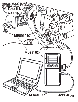
- Connect scan tool MB991958 to the data link connector.
- Turn the ignition switch to the "ON" position.
- Diagnose the CAN bus line.
- Turn the ignition switch to the "LOCK" (OFF) position.
Q: Is the CAN bus line found to be normal?
YES : Go to Step 2.
NO : Repair the CAN bus line.
STEP 2. Register the key ID and recheck the diagnostic trouble code.
Register the key ID of the ignition key, and recheck if the DTC is set.
- Turn the ignition switch from the "LOCK" (OFF) position to the "ON" position.
- Check if the DTC is set.
Q: Is the DTC set?
YES : Go to Step 3.
NO : The procedure is complete.
STEP 3. Replace the ignition key and recheck the diagnostic trouble code.
Replace the ignition key by which the DTC is set with the other key, and recheck if the DTC is set.
- Turn the ignition switch from the "LOCK" (OFF) position to the "ON" position.
- Check if the DTC is set.
Q: Is the DTC set?
YES : Go to Step 4.
NO : Go to Step 5.
STEP 4. Register the key ID and recheck the diagnostic trouble code.
Register the key ID of the ignition key, and recheck if the DTC is set.
- Turn the ignition switch from the "LOCK" (OFF) position to the "ON" position.
- Check if the DTC is set.
Q: Is the DTC set?
YES : Go to Step 5.
NO : The procedure is complete.
STEP 5. Replace the ignition key and recheck the diagnostic trouble code.
Replace the ignition key with a new one, register the key ID and keyless ID of the new key, and recheck if the DTC is set.
- Turn the ignition switch from the "LOCK" (OFF) position to the "ON" position.
- Check if the DTC is set.
Q: Is the DTC set?
YES : Replace WCM and register the ID codes.
NO : The procedure is complete.
DTC B1A28: Engine control module authenticate error
CAUTION
- When the DTC B1A28 is set, be sure to diagnose the CAN bus line.
- When replacing the ECU, always check that the communication circuit is normal.
DTC SET CONDITION
WCM sets DTC B1A28 when the ignition key certification result and the engine control module starting condition do not match.
TECHNICAL DESCRIPTION (COMMENT)
WCM determines that the abnormality is present, if the key certification result and the engine control module starting condition do not match after the engine start permission communication is completed.
TROUBLESHOOTING HINTS
- Malfunction of CAN bus line
- Malfunction of WCM
- Engine control module malfunction
- VIN registered in engine control module unmatched
DIAGNOSIS
Required Special Tools:
- MB991958: Scan Tool (M.U.T.-III Sub Assembly)
- MB991824: Vehicle Communication Interface (V.C.I.)
- MB991827: M.U.T.-III USB Cable
- MB991910: M.U.T.-III Main Harness A (Vehicles with CAN communication system)
STEP 1. Using scan tool MB991958, diagnose the CAN bus line.
CAUTION To prevent damage to scan tool (MB991958), always turn the ignition switch to the "LOCK" (OFF) position before connecting or disconnecting scan tool (MB991958).
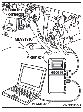
- Connect scan tool MB991958 to the data link connector.
- Turn the ignition switch to the "ON" position.
- Diagnose the CAN bus line.
- Turn the ignition switch to the "LOCK" (OFF) position.
Q: Is the CAN bus line found to be normal?
YES : Go to Step 2.
NO : Repair the CAN bus line.
STEP 2. Using scan tool MB991958, read the engine control module diagnostic trouble code.
Check again if the DTC is set to the engine control module.
Q: Is the DTC set?
YES : Troubleshoot the MFI system (Refer to GROUP 13A, Diagnostic trouble code chart <2.4L Engine> or GROUP 13B, Diagnostic trouble code chart <3.0L Engine>).
NO : Go to Step 3.
STEP 3. Using scan tool MB991958, read the diagnostic trouble code.
Check if the DTC is set to the WCM.
- Turn the ignition switch from the "LOCK" (OFF) position to the "ON" position.
- Check if the DTC is set.
Q: Is DTC B1761 or B2206 set other than B1A28?
YES : Perform the troubleshooting for each DTC.
NO : Go to Step 4.
STEP 4. Recheck for diagnostic trouble code.
Check again if the DTC is set to the WCM.
- Turn the ignition switch from the "LOCK" (OFF) position to the "ON" position.
- Check if the DTC is set.
Q: Is the DTC set?
YES : Replace WCM and register the ID codes. Then go to Step 5.
NO : The diagnosis is complete.
STEP 5. Recheck for diagnostic trouble code.
Check again if the DTC is set to the WCM.
- Turn the ignition switch from the "LOCK" (OFF) position to the "ON" position.
- Check if the DTC is set.
Q: Is the DTC set?
YES : Replace the engine control module and record VIN.
NO : The procedure is complete.
DTC B1A35: Transponder read error
CAUTION
- When DTC B1A35 is set, be sure to diagnose the CAN bus line.
- When replacing the ECU, always check that the communication circuit is normal.
DTC SET CONDITION
WCM sets DTC B1A35 when it cannot receive data from the transponder.
TECHNICAL DESCRIPTION (COMMENT)
WCM determines that the abnormality is present, if it cannot receive the key ID for the ignition key when the ignition switch is turned ON.
TROUBLESHOOTING HINTS
- Malfunction of the ignition key
- Malfunction of WCM
- Interference of the encrypted code
DIAGNOSIS
Required Special Tools:
- MB991958: Scan Tool (M.U.T.-III Sub Assembly)
- MB991824: Vehicle Communication Interface (V.C.I.)
- MB991827: M.U.T.-III USB Cable
- MB991910: M.U.T.-III Main Harness A (Vehicles with CAN communication system)
STEP 1. Using scan tool MB991958, diagnose the CAN bus line.
CAUTION To prevent damage to scan tool (MB991958), always turn the ignition switch to the "LOCK" (OFF) position before connecting or disconnecting scan tool (MB991958).
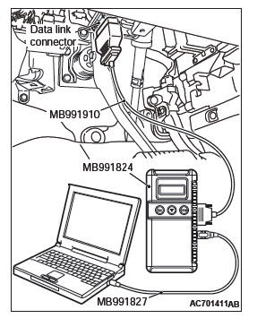
- Connect scan tool MB991958 to the data link connector.
- Turn the ignition switch to the "ON" position.
- Diagnose the CAN bus line.
- Turn the ignition switch to the "LOCK" (OFF) position.
Q: Is the CAN bus line found to be normal?
YES : Go to Step 2.
NO : Repair the CAN bus line.
STEP 2. Check the ignition key inserted in the key cylinder for interference.
Q: Are there other ignition keys or anything that interferes with the communication (things that generate radio waves such as magnets or air-cleaning device that has a power plug) near the ignition key inserted in the key cylinder?
YES : Move away or remove other ignition keys or anything that interferes with the communication, and go to Step 3.
NO : Go to Step 3.
STEP 3. Recheck for diagnostic trouble code.
Check again if the DTC is set to the WCM.
- Turn the ignition switch from the "LOCK" (OFF) position to the "ON" position.
- Check if the DTC is set.
Q: Is the DTC set?
YES : Go to Step 4.
NO : The procedure is complete.
STEP 4. Replace the ignition key and recheck the diagnostic trouble code.
Replace the ignition key by which the DTC is set with the other key, and recheck if the DTC is set.
- Turn the ignition switch from the "LOCK" (OFF) position to the "ON" position.
- Check if the DTC is set.
Q: Is the DTC set?
YES : Go to Step 5.
NO : Go to Step 6.
STEP 5. Register the key ID and recheck the diagnostic trouble code.
Register the key ID of the ignition key, and recheck if the DTC is set.
- Turn the ignition switch from the "LOCK" (OFF) position to the "ON" position.
- Check if the DTC is set.
Q: Is the DTC set?
YES : Go to Step 6.
NO : The procedure is complete.
STEP 6. Replace the ignition key and recheck the diagnostic trouble code.
Replace the ignition key by which the DTC is set with a new one, register the key ID of the new key, and recheck if the DTC is set.
- Turn the ignition switch from the "LOCK" (OFF) position to the "ON" position.
- Check if the DTC is set.
Q: Is the DTC set?
YES : Replace WCM and register the ID codes.
NO : The procedure is complete.
DTC B2101: IG SW start POS.circuit low
DTC B2102: IG SW start POS.circuit high
CAUTION
- If DTC B2101 or B2102 is set, be sure to diagnose the CAN bus line.
- Before replacing the ECU, ensure that the communication circuit is normal.
WCM Communication Circuit
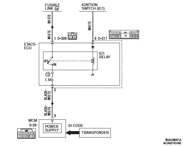

DTC SET CONDITION
WCM sets DTC B2101 or B2012 when the actual state of the ignition switch and the ignition switch position information received from ETACS-ECU via CAN do not match.
TECHNICAL DESCRIPTION (COMMENT)
WCM determines that the abnormality is present, if it has detected discrepancy in the ignition switch level shown below ten consecutive times when WCM has received the CAN message (ignition switch position information) from ETACS-ECU with the ignition switch turned to the ON or START position.
B2101
- Status of ignition switch: OFF position
- Ignition switch position information from the ETACS-ECU: ON
B2102
- Status of ignition switch: ON position
- Ignition switch position information from the ETACS-ECU: OFF
TROUBLESHOOTING HINTS
- Malfunction of CAN bus line
- Malfunction of the WCM
- Malfunction of the ignition switch
- Damaged wiring harness and connectors
- Malfunction of ETACS-ECU
DIAGNOSIS
Required Special Tools:
- MB991958: Scan Tool (M.U.T.-III Sub Assembly)
- MB991824: Vehicle Communication Interface (V.C.I.)
- MB991827: M.U.T.-III USB Cable
- MB991910: M.U.T.-III Main Harness A (Vehicles with CAN communication system)
STEP 1. Using scan tool MB991958, diagnose the CAN bus line.
CAUTION To prevent damage to scan tool (MB991958), always turn the ignition switch to the "LOCK" (OFF) position before connecting or disconnecting scan tool (MB991958).
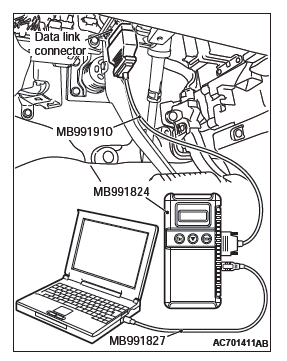
- Connect scan tool MB991958 to the data link connector.
- Turn the ignition switch to the "ON" position.
- Diagnose the CAN bus line.
- Turn the ignition switch to the "LOCK" (OFF) position.
Q: Is the CAN bus line found to be normal?
YES : Go to Step 2.
NO : Repair the CAN bus line.
STEP 2. Check ETACS-ECU connector C-317 and WCM connector C-29 for loose, corroded or damaged terminals, or terminals pushed back in the connector.
Q: Is ETACS-ECU connector C-317 and WCM connector C-29 in good condition?
YES : Go to Step 3.
NO : Repair the defective connector.
STEP 3. Check the wiring harness between WCM connector C-29 (terminal No.9) and ETACS-ECU connector C-317 (terminal No.5).
Check the power supply line for open circuit.
Q: Is the wiring harness between WCM connector C-29 (terminal No. 9) and ETACS-ECU connector C-317 (terminal No. 5) in good condition?
YES : Go to Step 4.
NO : The wiring harness may be damaged or the connector(s) may have loose, corroded or damaged terminals, or terminals pushed back in the connector.
STEP 4. Using scan tool MB991958, check data list.
Use the ETACS-ECU data list to check the signals related to the ignition voltage.
Turn the ignition switch from "LOCK" (OFF) position to "ON" position.

Q: Does scan tool MB991958 display the item "IG voltage" as normal condition?
YES : Go to Step 5.
NO : Diagnose the ETACS-ECU.
STEP 5. Recheck for diagnostic trouble code.
Check again if the DTC is set to the WCM.
- Erase the DTC.
- Turn the ignition switch from "LOCK" (OFF) position to "ON" position.
- Check if DTC is set.
- Turn the ignition switch to the "LOCK" (OFF) position.
Q: Is the DTC set?
YES : Replace WCM and register the ID codes. NO : The trouble can be an intermittent malfunction.

