Mitsubishi Outlander: Inspection Procedure
Inspection Procedure 1: Scan tool cannot communicate with WCM.
CAUTION Before replacing the ECU, ensure that the communication circuit is normal.
TECHNICAL DESCRIPTION (COMMENT)
If the scan tool cannot communicate with the WCM, the CAN bus lines may be defective. If the WCM does not work, the WCM or the power supply circuit may be defective.
TROUBLESHOOTING HINTS
- Malfunction of the power supply or ground of WCM
- Malfunction of CAN bus line
- Malfunction of WCM
DIAGNOSIS
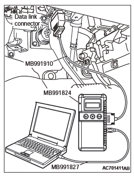
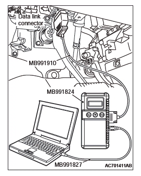
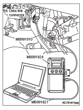
Required Special Tools:
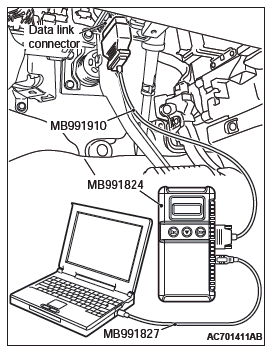
- MB991958: Scan Tool (M.U.T.-III Sub Assembly)
- MB991824: Vehicle Communication Interface (V.C.I.)
- MB991827: M.U.T.-III USB Cable
- MB991910: M.U.T.-III Main Harness A (Vehicles with CAN communication system)
STEP 1. Using scan tool MB991958, diagnose the CAN bus line.
CAUTION To prevent damage to scan tool MB991958, always turn the ignition switch to the "LOCK" (OFF) position before connecting or disconnecting scan tool MB991958.
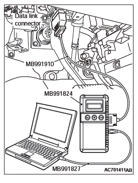
- Connect scan tool MB991958. Refer to "How to connect the Scan Tool (M.U.T.-III)".
- Turn the ignition switch to the "ON" position.
- Diagnose the CAN bus line.
- Turn the ignition switch to the "LOCK" (OFF) position.
Q: Is the CAN bus line found to be normal?
YES : Go to Step 2.
NO : Repair the CAN bus line.
STEP 2. Check the power supply circuit and the ground circuit to WCM.
Refer to Inspection Procedure 4 "Abnormality in WCM power supply and ground circuits".
Q: Are the power supply circuit and the ground circuit to WCM in good condition ?
YES : Go to Step 3.
NO : Repair the power supply circuit and the ground circuit to WCM.
STEP 3. Retest the system
Check if scan tool can communicate with WCM.
Q: Does the scan tool cannot communicate with WCM in good condition?
YES : The trouble can be an intermittent malfunction.
NO : Replace WCM and register the ID codes.
Inspection Procedure 2: The ignition key cannot be registered using scan tool.
TECHNICAL DESCRIPTION (COMMENT)
If only some ignition keys cannot be registered, the ignition key itself may be faulty. If no ignition key can be registered, the key assembly may have already been registered for another vehicle, or the WCM may be faulty.
TROUBLESHOOTING HINTS
- Malfunction of the ignition key
- Damaged wiring harness and connectors
- Malfunction of WCM
- Ignition key registered for other vehicle
DIAGNOSIS
Required Special Tools:
- MB991958: Scan Tool (M.U.T.-III Sub Assembly)
- MB991824: Vehicle Communication Interface (V.C.I.)
- MB991827: M.U.T.-III USB Cable
- MB991910: M.U.T.-III Main Harness A (Vehicles with CAN communication system)
STEP 1. Check the ignition key inserted in the key cylinder for interference.
Q: Are there other ignition keys or anything that interferes with the communication (things that generate radio waves such as magnets and an air-cleaning device that has a power plug) near the ignition key inserted in the key cylinder?
YES : Move away or remove other ignition keys or things that interfere with the communication (things that generate radio waves such as magnets and a air-cleaning device that has a power plug) near the ignition key. Then, go to step 2.
NO : Go to Step 3.
STEP 2. Retest the system
Check that the ignition key can be registered.
Q: Is the ignition key that cannot be registered using scan tool in good condition?
YES : The procedure is complete.
NO : Go to Step 3.
STEP 3. Check which ignition key cannot be registered.
Q: Can any one of the ignition keys be registered?
YES (Only some keys) : Replace the key that cannot be registered and register the ID codes. After registering the ID codes, go to Step 5.
NO (All keys) : Go to Step 4.
STEP 4. Retest the system
Check the scan tool screen when the key was not able to be registered.
Q: Is the error message of scan tool screen "Abnormality in key" ?
YES (Abnormality in key) : Carry out DTC B1A25: Transponder ID unmatched and DTC B1A35: Transponder read error. Then, go to Step 5.
NO (ECU internal error) : Replace WCM and register the ID codes. After registering the ID codes, go to Step 5.
STEP 5. Retest the system
Check that the ignition key can be registered.
Q: Is the ignition key cannot be registered using scan tool in good condition?
YES : The procedure is complete.
NO : Replace WCM and register the ID codes.
Inspection Procedure 3: Engine does not start.
TECHNICAL DESCRIPTION (COMMENT)
If the fuel injection does not work, WCM and the MFI system may have a problem. This symptom is not considered abnormal when the engine is started by an ignition key that has not been registered.
TROUBLESHOOTING HINTS
- Malfunction of battery
- Malfunction of the MFI system
- Malfunction of WCM
- Malfunction of CAN bus line
- Malfunction of the transponder
- VIN not programmed
DIAGNOSIS
Required Special Tools:
- MB991958: Scan Tool (M.U.T.-III Sub Assembly)
- MB991824: Vehicle Communication Interface (V.C.I.)
- MB991827: M.U.T.-III USB Cable
- MB991910: M.U.T.-III Main Harness A (Vehicles with CAN communication system)
STEP 1. Check the battery voltage.
Measure the battery voltage when cranking.
- The voltage should measure 8 volt or more.
Q: Is the measured voltage 8 volt or more?
YES : Go to Step 2.
NO : Check the battery.
STEP 2. Using scan tool MB991958, diagnose the CAN bus line.
CAUTION To prevent damage to scan tool MB991958, always turn the ignition switch to the "LOCK" (OFF) position before connecting or disconnecting scan tool MB991958.
- Connect scan tool MB991958. Refer to "How to connect the Scan Tool (M.U.T.-III)".
- Turn the ignition switch to the "ON" position.
- Diagnose the CAN bus line.
- Turn the ignition switch to the "LOCK" (OFF) position.
Q: Is the CAN bus line found to be normal?
YES : Go to Step 3.
NO : Repair the CAN bus line.
STEP 3. Using scan tool MB991958, read the MFI system diagnostic trouble code.
Check if DTC is set to the engine control module.
Q: Is the DTC set?
YES : Troubleshoot the MFI system.
NO : Go to Step 4.
STEP 4. Using scan tool MB991958, read the WCM diagnostic trouble code.
Check if DTC is set to the WCM.
Q: Is the DTC set?
YES : Troubleshoot the WCM.
NO : Go to Step 5.
STEP 5. Check that the engine starts.
Q: Does the engine start?
YES : The procedure is complete.
NO : Refer to GROUP 13A, Diagnosis <2.4L Engine> or GROUP 13B, Diagnosis <3.0L Engine>. When the cause of the failure cannot be tracked down by the troubleshooting in GROUP 13A <2.4L Engine> or GROUP 13B <3.0L Engine>, replace WCM and register the ID codes.
Inspection Procedure 4: Abnormality in WCM power supply and ground circuits.
CAUTION Before replacing the ECU, ensure that the power supply circuit, the ground circuit and the communication circuit are normal.
WCM Power Supply Circuit
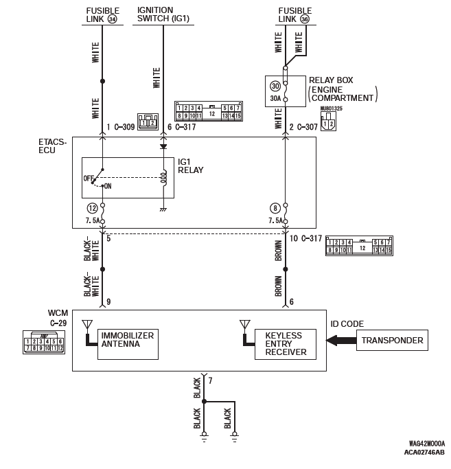
TECHNICAL DESCRIPTION (COMMENT)
If the WCM does not work at all or if the WCM cannot communicate with the scan tool, the WCM power supply or the ground circuit may be defective.
TROUBLESHOOTING HINTS
- Damaged wiring harness and connectors
- Malfunction of the WCM
DIAGNOSIS
Required Special Tools:
- MB992006: Extra fine probe
- MB991223: Harness set
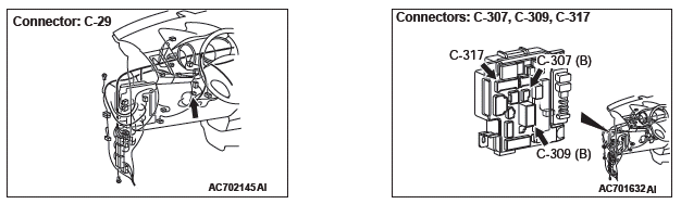
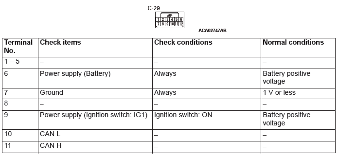
STEP 1. Check WCM connector C-29 and ETACS-ECU connector C-317 for loose, corroded or damaged terminals, or terminals pushed back in the connector.
Q: Is the WCM connector C-29 and ETACS-ECU connector C-317 in good condition?
YES : Go to Step 2.
NO : Repair the defective connector.
STEP 2. Check the wiring harness between WCM connector C-29 (terminal No.6, 9) and the ETACS-ECU connector C-317 (terminal No.10, 5) for open circuit.
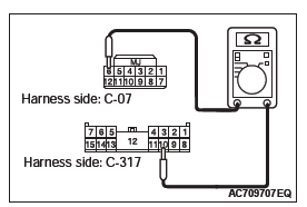
- Disconnect WCM connector C-29 and ETACS-ECU connector C-317, and check the wiring harness.
- Check the wiring harness between WCM connector C-29
(terminal No.6) and ETACS-ECU connector C-317 (terminal
No.10).
OK: Continuity exists (2 Ω or less)
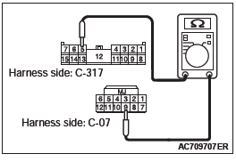
- Check the wiring harness between WCM connector C-29
(terminal No.9) and ETACS-ECU connector C-317 (terminal
No.5).
OK: Continuity exists (2 Ω or less)
Q: Is the wiring harness between WCM connector C-29 and the ETACS-ECU connector C-317 in good condition?
YES : Go to Step 3.
NO : Repair the wiring harness between WCM connector C-07 (terminal No.6, 9) and ETACS-ECU connector C-317 (terminal No.10, 5).
STEP 3. Check the wiring harness between the WCM connector C-29 (terminal No.7) and the ground for open circuit.
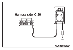
- Disconnect the connector and measure the resistance at the wiring harness side.
- Turn the ignition switch to the ON position.
- Measure the resistance between terminal No.7 and the
ground.
OK: Continuity exists (2 Ω or less)
Q: Is the wiring harness between WCM connector C-29 and the ground in good condition?
YES : Go to Step 4.
NO : Repair the wiring harness between WCM connector C-29 (terminal No.7) and ground.
STEP 4. Retest the system
Q: Does the abnormality in WCM power supply and ground circuits in good condition?
YES : The trouble can be an intermittent malfunction.
NO : Replace WCM and register the ID codes.
Inspection Procedure 5: Keyless entry system does not work.
CAUTION Before replacing the ECU, ensure that the power supply circuit, the ground circuit and the communication circuit are normal.
OPERATION
The lock/unlock signals from the transmitter are received by WCM, and then sent to ETACS-ECU from WCM. When ETACS-ECU receives signals from the key reminder switch and all the door switches, ETACS-ECU actuates the keyless entry system.
PROBABLE CAUSES
- Malfunction of the key reminder switch
- Malfunction of the door switches
- Malfunction of keyless entry transmitter
- Malfunction of the WCM
- Malfunction of ETACS-ECU
- Damaged wiring harness and connectors
- Option coding information
DIAGNOSTIC PROCEDURE
Required Special Tools:
- MB991223: Harness Set
- MB992006: Extra Fine Probe
- MB991958: Scan Tool (M.U.T.-III Sub Assembly)
- MB991824: V.C.I.
- MB991827: M.U.T.-III USB Cable
- MB991910: M.U.T.-III Main Harness A
STEP 1. Scan tool (M.U.T.-III) CAN bus diagnostics
Use scan tool MB991958 (M.U.T.-III), diagnose the CAN bus lines.
Q: Is the CAN bus normal?
YES : Go to Step 2.
NO : Repair the CAN bus line.
STEP 2. Using scan tool MB991958, read the diagnostic trouble code.
CAUTION To prevent damage to scan tool MB991958, always turn the ignition switch to the "LOCK" (OFF) position before connecting or disconnecting scan tool MB991958.
- Connect scan tool MB991958. Refer to "How to connect scan tool (M.U.T.-III)".
- Turn the ignition switch to the "ON" position.
- Check whether the ETACS-ECU related DTC is set.
- Turn the ignition switch to the "LOCK" (OFF) position.
Q: Is the DTC set?
YES : Diagnose the ETACS-ECU.
NO : Go to Step 3.
STEP 3. Check the power supply system
With the ignition switch in the LOCK (OFF) position, check if the following function operates normally:
- Headlight
- Hazard warning light
Q: Is the check result normal?
YES : Go to Step 4.
NO : Refer to GROUP 54A, Malfunction of ETACS-ECU power supply circuit.
STEP 4. Verify the central door locking system.
Q: Does the central door locking system work normally?
YES : Go to Step 5.
NO : Refer to GROUP 42A, Trouble Symptom Chart.
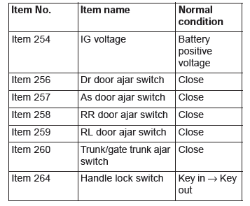
STEP 5. Using scan tool MB991958, check data list.
Check the signals related to the keyless entry system operation.
CAUTION To prevent damage to scan tool MB991958, always turn the ignition switch to the "LOCK" (OFF) position before connecting or disconnecting scan tool MB991958.
- Connect scan tool MB991958. Refer to "How to connect the Scan Tool (M.U.T.-III)".
- Turn the ignition switch to the "ON" position.
- Check the ETACS data list.
- Turn the ignition switch to the LOCK (OFF) position.
- Close the driver's door.
- Close the passenger's door.
- Close the RH-side rear door.
- Close the LH-side rear door.
- Close the liftgate.
- Remove the ignition key from the ignition key cylinder.
- Turn the ignition switch to the "LOCK" (OFF) position.
OK: Normal condition are displayed.
Q: Are the check result normal?
YES (Normal conditions are displayed for all the items.) : Go to Step 6.
NO (Normal condition is not displayed for item No. 254.) : Refer to GROUP 54A, Inspection Procedure 2: ETACS-ECU does not receive any signal from the ignition switch (IG1).
NO (Normal condition is not displayed for item No. 256.) : Refer to GROUP 54A, Inspection Procedure 5: ETACS-ECU does not receive any signal from the front door switch (LH).
NO (Normal condition is not displayed for item No. 257.) : Refer to GROUP 54A, Inspection Procedure 6: ETACS-ECU does not receive any signal from the front door switch (RH).
NO (Normal condition is not displayed for item No. 258.) : Refer to GROUP 54A, Inspection Procedure 8: ETACS-ECU does not receive any signal from the rear door switch (RH).
NO (Normal condition is not displayed for item No. 259.) : Refer to GROUP 54A, Inspection Procedure 7: ETACS-ECU does not receive any signal from the rear door switch (LH).
NO (Normal condition is not displayed for item No. 260.) : Refer to GROUP 54A, Inspection Procedure 9: ETACS-ECU does not receive any signal from the liftgate switch.
NO (Normal condition is not displayed for item No. 264.) : Refer to GROUP 54A, Inspection Procedure 3: ETACS-ECU does not receive any signal from the key reminder switch.
STEP 6. Retest the system.
Check if the keyless entry system works normally.
Q: Is the check result normal?
YES : Intermittent malfunction.
NO : Replace WCM and register the ID codes.
Inspection Procedure 6: The dome light, the turn-signal lights and the horn do not operate through the answerback function.
CAUTION Before replacing the ECU, ensure that the power supply circuit, the ground circuit and the communication circuit are normal.
COMMENTS ON TROUBLE SYMPTOM
If the hazard warning light, the dome light and the horn work normally, ETACS-ECU may be faulty. Also, the answerback function may have been disabled using the customization function.
If the theft alarm is defective, the keyless entry hazard answerback function may not operate normally.
PROBABLE CAUSES
- Malfunction of the turn signal light
- Malfunction of the dome light
- Malfunction of the horn
- Malfunction of the theft alarm sensor
- Malfunction of the theft alarm siren
- Malfunction of ETACS-ECU
- Damaged wiring harness and connectors
DIAGNOSTIC PROCEDURE
STEP 1. Verify the hazard warning lights.
Check that the hazard warning lights illuminate normally.
Q: Is the check result normal?
YES : Go to Step 2.
NO : Refer to GROUP 54A, Inspection Procedure 1: The Hazard Warning lights do not Illuminate.
STEP 2. Verify the dome light.
Check that the dome light illuminate normally.
Q: Is the check result normal?
YES : Go to Step 3.
NO : Refer to GROUP 54A, Trouble Symptom Chart.
STEP 3. Verify the horn.
Check that the horn normally.
Q: Is the check result normal?
YES : Go to Step 4.
NO : Replace the horn.
STEP 4. Check the operation of the keyless entry system.
Operate the transmitter and check that all doors (including the liftgate) lock and unlock.
Q: Is the check result normal?
YES : Go to Step 5.
NO : Refer to P.42C.
STEP 5. Check the customize function.
Check that any one of the followings other than "Lock: 0, Unlock: 0" is set for "Hazard answerback" with a customization function.
- Lock:1, Unlock:2
- Lock:1, Unlock:0
- Lock:0, Unlock:2
- Lock:2, Unlock:1
- Lock:2, Unlock:0
- Lock:0, Unlock:1
Q: Is the check result normal?
YES : Go to Step 6.
NO : Set "Hazard answerback" to any one other than "Lock: 0, Unlock: 0" with a customization function.
STEP 6. Check the customize function.
Check that any one of the followings other than "Not sound horn" is set for "Horn chirp by RKE" with a customization function.
- Lock any time
- W lock any time
Q: Is the check result normal?
YES : Go to Step 7.
NO : Set "Horn chirp by RKE" to any one other than "Not sound horn" with a customization function.
STEP 7. Using scan tool MB991958, read the diagnostic trouble code.
CAUTION To prevent damage to scan tool MB991958, always turn the ignition switch to the "LOCK" (OFF) position before connecting or disconnecting scan tool MB991958.
- Connect scan tool MB991958. Refer to "How to connect scan tool (M.U.T.-III)".
- Turn the ignition switch to the "ON" position.
- Check whether the theft alarm related DTC is set.
- Turn the ignition switch to the "LOCK" (OFF) position.
Q: Is the DTC set?
YES : Diagnose the theft alarm.
NO : Go to Step 8.
STEP 8. Check of the troubles.
Check if the keyless entry answerback function works normally.
Q: Is the check result normal?
YES : Intermittent malfunction.
NO : Replace ETACS-ECU.
Inspection Procedure 7: The timer lock function does not work after the doors have been unlocked by the keyless entry system.
CAUTION Before replacing the ECU, ensure that the power supply circuit, the ground circuit and the communication circuit are normal.
COMMENTS ON TROUBLE SYMPTOM
If the timer lock function does not work normally, the keyless entry transmitter input signal circuit or ETACS-ECU may be faulty.
PROBABLE CAUSES
- Malfunction of keyless entry transmitter
- Malfunction of ETACS-ECU
- Damaged wiring harness and connectors
DIAGNOSTIC PROCEDURE
STEP 1. Verify the keyless entry system.
Q: Does the keyless entry system work normally?
YES : Go to Step 2.
NO : Refer to P.42C.
STEP 2. Check the customize function.
The "Timer lock timer" has been set to one of the followings with the customization function. Check if the doors are locked at the set period.
- 30sec
- 60sec
- 120sec
- 180sec
Q: Is the check result normal?
YES : Go to Step 3.
NO : Set "Timer lock timer" to one of the time above with a customization function.
STEP 3. Check of the troubles
Check that the keyless entry system works normally.
Q: Is the check result normal?
YES : Intermittent malfunction.
NO : Replace ETACS-ECU.
Inspection Procedure 8: Power door locks with selective unlocking does not work.
CAUTION Before replacing the ECU, ensure that the power supply circuit, the ground circuit and the communication circuit are normal.
COMMENT ON TROUBLE SYMPTOM
If the keyless entry function works normally and only the power door locks with selective unlocking does not work normally, ETACS-ECU may be defective. In addition, it is possible that the function has been disabled by using the customization function.
PROBABLE CAUSES
- Malfunction of ETACS-ECU
- Damaged wiring harness and connectors
DIAGNOSIS PROCEDURE
STEP 1. Check the customization
Q: Are the power door locks with selective unlocking enabled by the customization function?
YES : Go to Step 2.
NO : Set the power door locks with selective unlocking to "Enabled" by using the customization function.
STEP 2. Keyless entry system operation check
Press the unlock switch of the transmitter and check that only the driver's door is unlocked. Then, press the unlock switch once again within 2 seconds after that to check that the front passenger's door, the rear doors and the liftgate are unlocked.
Q: Does the keyless entry system work normally?
YES : Go to Step 3.
NO (Only the driver's door is not unlocked.) : Replace the ETACS-ECU.
NO (The driver's door, front passenger's door, rear doors and liftgate are not unlocked.) : Refer to Inspection Procedure 5: "Keyless entry system does not work"
STEP 3. Check of the troubles
Check that the power door locks with selective unlocking works normally.
Q: Is the check result normal?
YES : Intermittent malfunction.
NO : Replace ETACS-ECU.
DATA LIST REFERENCE TABLE
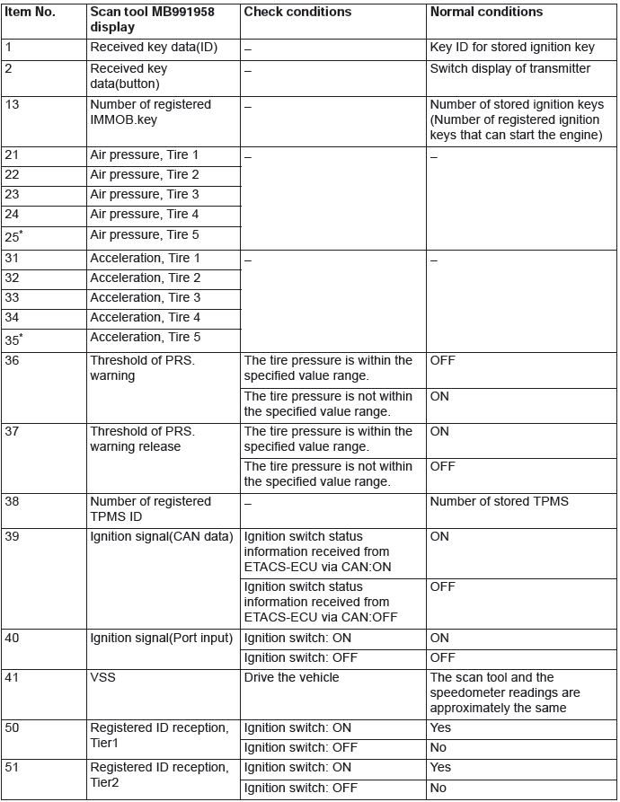
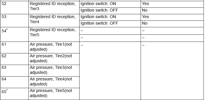
NOTE: * shows that it is displayed but not used.
CHECK AT ECU TERMINALS
READ NEXT:
 On-vehicle Service
ID CODES REGISTRATION PROCEDURE
REGISTRATION USING SCAN TOOL MB991958
(M.U.T.-III SUB ASSEMBLY)
Required Special Tools:
MB991958 Scan Tool (M.U.T.-III Sub Assembly)
MB991824: Vehicle Communication
WCM, Transmitter, TPMS Transmitter
WCM
REMOVAL AND INSTALLATION
CAUTION
When WCM has been replaced, all key ID codes should be registered, referring to
the ID code registration
judgment table.
NOTE: Claw position is symmetrical
Remo
SEE MORE:
Rear Disc Brake Assembly
REMOVAL AND INSTALLATION <2.4L ENGINE: 5 PERSONS SEAT>
Pre-removal operation
Brake Fluid Draining
Post-installation operation
Brake Fluid Refilling and Air Bleeding
Brake Disk Runout Inspection/Correction
Parking Brake Lining Seating Procedure
Removal steps
Brake tube (brake hose s
Replacement of lamp bulbs
Before replacing a bulb, ensure the lamp is off. Do not touch the glass part
of the new bulb with your bare fingers; the skin oil left on the glass will evaporate
when the bulb gets hot and the vapour will condense on the reflector and dim the
surface.
CAUTION:
● Bulbs are extremely ho
