Mitsubishi Outlander: WCM, Transmitter, TPMS Transmitter
WCM
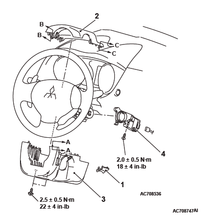
REMOVAL AND INSTALLATION
CAUTION When WCM has been replaced, all key ID codes should be registered, referring to the ID code registration judgment table.
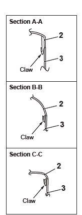
NOTE: Claw position is symmetrical
Removal steps
- Ignition key cover
- Steering column upper cover
- Steering column lower cover
- WCM
INSTALLATION SERVICE POINT
WCM INSTALLATION
Check that the top claw of WCM is fixed securely to the boss of steering lock and the antenna is not floated on the key cylinder.
Transmitter
DISASSEMBLY AND ASSEMBLY
Post-installation operation
- Transmitter operation check
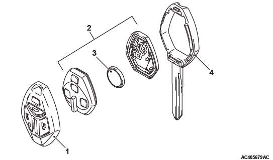
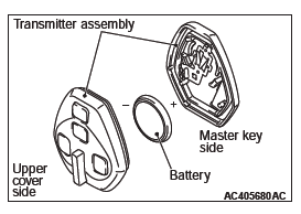
Disassembly steps
- Upper cover
- Transmitter assembly
- Battery
- Master key
DISASSEMBLY SERVICE POINTS
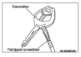
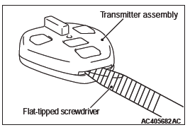
UPPER COVER REMOVAL
CAUTION To prevent damage to the transmitter, wrap a flat-tipped screwdriver with protective tape before prying.
Insert a flat-tipped screwdriver in the area shown, and remove the upper cover by prying it with the screwdriver.
BATTERY REMOVAL
CAUTION
- Do not allow water or dust to enter the inside of the transmitter assembly when it is open. Also, do not touch the precision electronic device.
- To prevent damage to the transmitter assembly, wrap a flat-tipped screwdriver with protective tape before prying.
Insert a flat-tipped screwdriver in the area shown, and remove the battery by prying it with the screwdriver.
ASSEMBLY SERVICE POINT
BATTERY INSTALLATION
CAUTION Do not allow water or dust to enter the inside of the transmitter assembly when it is open. Also, do not touch the precision electronic device.
Install a new battery to the transmitter assembly with its (+) side facing towards the master key side.
Battery required for replacement: Coin type battery CR1620
TPMS Transmitter
REMOVAL AND INSTALLATION
WARNING Certain components of this vehicles, such as TPMS transmitters, may contain perchlorate materials. Special handling may apply. For additional information, see www.dtsc.ca.gov/hazardouswaste/ perchlorate.
CAUTION
- Ensure valve cap is always in place except when adjusting tire pressure.
- If the valve core and valve cap are replaced, use a genuine replacement part. The valve core is similar to a conventional one, but uses nickel plating to avoid corrosion.
- Replace the seal washer with a new one when the tire is replaced.
- Do not drop the TPMS transmitter from height greater than 1 meter (3.3 feet).
- Do not expose the TPMS transmitter to extraneous magnetic fields.
- TPMS transmitter should not be stored at temperatures above 80ºC (176ºF).
- TPMS transmitter should not be exposed to temperatures above 100ºC (212ºF).
- If the TPMS transmitter is replaced, execute "Tire Pressure Sensor ID Registration" on scan tool MB991958 "Special Function".
- Be careful not to damage the TPMS transmitter.
Pre-removal Operation
- Wheel and Tire Removal
Post-installation Operation
- Wheel and Tire Installation
- Tire Pressure Sensor ID Registration If a new TPMS transmitter is installed
- After the tire pressure sensor ID registration, check that the TPMS warning light does not illuminate or flash
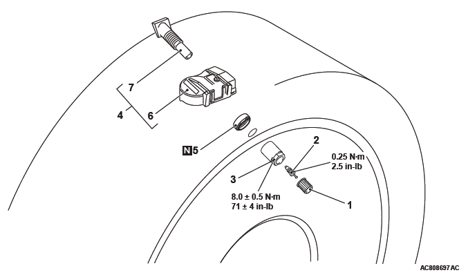
Removal steps
- Cap
- Valve core
- Nut
- Let TPMS transmitter fall into tire
- Tire bead
- TPMS transmitter
- Seal washer
- Housing <Incase of removing the valve>
- Valve <Incase of removing the valve>
Installation steps
- Housing <In case of installing the valve>
- Valve <In case of installing the valve>
- Seal washer
- TPMS transmitter
- Nut
- Tire bead mounting
- Valve core
- Tire pressure inflation
- Valve nut retightening
- Cap
REMOVAL SERVICE POINTS
CAP/VALVE CORE/NUT REMOVAL
CAUTION Ensure cap is always in place except when adjusting tire pressure.
1. Remove the valve cap.
2. Rotate tire so that valve stem is in the 6 o'clock position.
3. Use a long-reach 17.2 mm (0.68 inch) socket to unscrew the valve nut a few turns. Slowly push valve stem into tire so that tire pressure is relieved.
4. Once tire pressure is released, remove nut and let TPMS transmitter fall into tire.
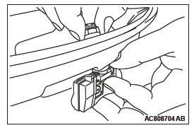
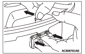
TPMS TRANSMITTER REMOVAL
CAUTION Be careful not to damage the TPMS transmitter.
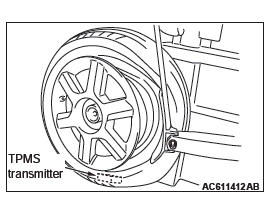
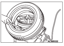
1. Place on tire changing machine and break both tire beads ensuring that the TPMS transmitter remains in the bottom of the tire.
2. Lubricate tire well and remove outer side of the tire.
3. Reach inside the tire and remove the TPMS transmitter.
4. Remove tire from rim using proper tire changing equipment procedures.
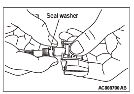
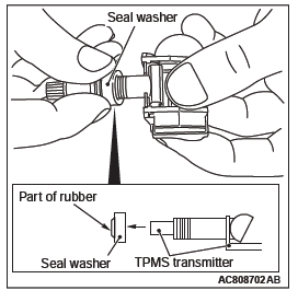
SEAL WASHER/VALVE REMOVAL
CAUTION Remove the seal washer to prevent scratching the valve of the TPMS transmitter.
1. Hold the TPMS transmitter and the seal washer, then extract the seal washer. Take care to not damage the valve thread.
2. Clean the TPMS transmitter and the valve stem. <In case of not removing the valve>
NOTE: If the valve comes out from the transmitter, install it to where it was. (This is not failure)
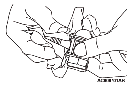
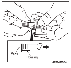
3. Removal the valve from housing as shown.
INSTALLATION SERVICE POINTS
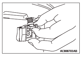
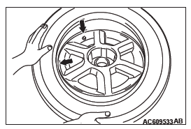
VALVE/SEAL WASHER/TPMS TRANSMITTER/ NUT INSTALLATION
CAUTION Install the seal washer to prevent scratching the valve of the TPMS transmitter.
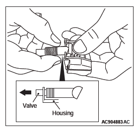
1. Install the valve to housing as shown.
2. Insert the seal washer up to the base of the TPMS transmitter, making sure to secure the valve base with a thumb as shown.
Wipe the seal and threading.
CAUTION
- Visually check that TPMS transmitter is not deformed or damaged.
- When installing the TPMS transmitter, be sure the rim, seal valve and nut are clean.
- Ensure the grommet is located inside the valve hole before installing the nut.
- While installing the nut, push the TPMS transmitter to maintain the lower lip of the transmitter case is in contact with the rim without clearance.
- While installing the valve nut, ensure the tool is kept aligned to the valve and the valve hole.
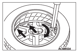
3. Install the valve, in the valve hole, without modifying the angle of the stem (retain position of delivery). The laser marking should be visible at the operator.
4. When the valve is completely inserted, maintain the TPMS transmitter in contact with the rim, then screw manually the nut until the contact with the wheel.
5. While maintaining the TPMS transmitter contact with the rim by applying pressure to the back of the valve, slightly press on the cap to wards the center of the wheel in order to adapt the angle of the valve/TPMS transmitter to the profile of the rim.
It is mandatory to guarantee the contact of the housing unit on the rim drop center.
6. While maintaining the TPMS transmitter and valve in position, screw the nut with a torque wrench.
Take care that the wrench socket is correctly inserted on the nut.
Specified torque: 8.0 +- 0.5 N*m (71 +- 4 in-lb)
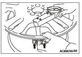
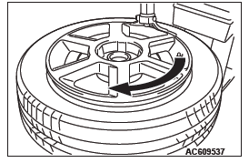
TIRE BEAD MOUNTING
1. Prepare the tire and fix the rim as usual.
2. Put the tire on the rim, so that the cross point of the belt with the rim is approximately 20 cm (7.9 inch) away from the valve.
3. Engage the shoe and make sure that 20 cm (7.9 inch) is maintained between the cross point and the valve.
The arrow shows the direction of rotation of the wheel.
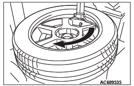
4. Turn the wheel in order to engage all the first side of the tire.
NOTE: The standard shoes can pass over the sensor without damaging it.
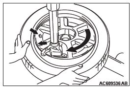
5. Put the second side of the tire in position, so that the cross point of the belt with the rim is approximately 20 cm (7.9 inch) away from the valve. The curved arrow shows the direction of rotation of the wheel.
6. Turn the wheel in order to engage all of the second side of the tire.
NOTE: The standard shoes can pass over the sensor without damaging it.
TIRE PRESSURE INFLATION/NUT RETIGHTENING
CAUTION After tire inflation, retighten the valve nut to 8.0 +- 0.5 N*m (71 +- 4 in-lb). This is necessary, because the TPMS transmitter is secured to the wheel with the valve nut and rubber grommet. The rubber grommet will be depressed by tire pressure or deteriorate over a period of time, which requires the valve nut to be retightened.
Inflate tire to required pressure, then retorque the valve nut to 8.0 +- 0.5 N*m (71 +- 4 in-lb).
READ NEXT:
 Specification(s), Front/Rear Bumper Assembly
Specification(s)
SERVICE SPECIVFICATIONS
ADHESIVES
LUBRICANT
Front Bumper Assembly
REMOVAL AND INSTALLATION
Pre-removal and post-installation operation
Headlight support panel cover removal and i
Radiator Grille, Moldings, Garnishes
Radiator Grille
REMOVAL AND INSTALLATION
Removal steps
Headlight support panel cover
Front bumper assembly
Radiator grille
Front-three diamond mark
Headlight support upper panel
cover
Mol
SEE MORE:
“Child-protection” rear doors
1- Lock.
2- Unlock.
Child protection helps prevent the rear doors from being opened accidentally
from the inside.
If the lever is set to the locked position, the rear doors cannot be opened using
the inside handle, but only with the outside handle.
If the lever is set to the “Unlock” p
Turn-signal lever
1- Turn-signals.
When making a normal turn, use position (1). The lever will return automatically
when cornering is completed.
2- Lane-change signals.
When moving the lever to (2) slightly to change a lane, the side turn-signal
lamps and indicator lamp in the instrument cluster will only fl
