Mitsubishi Outlander: Symptom Chart, Symptom Procedures
SYMPTOM CHART
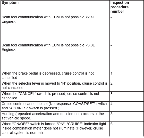
SYMPTOM PROCEDURES
Inspection Procedure 1: When the Brake Pedal is Depressed, Cruise Control System is not Cancelled.
COMMENT
- Malfunction of CAN bus line.
- The stoplight switch circuit is suspected.
TROUBLESHOOTING HINTS (THE MOST LIKELY CAUSES FOR THIS CASE:)
- Malfunction of CAN bus system.
- Damaged harness or connector.
- Malfunction of the stoplight switch.
- Malfunction of the ETACS-ECU
- Malfunction of the ECM.
DIAGNOSTIC PROCEDURE
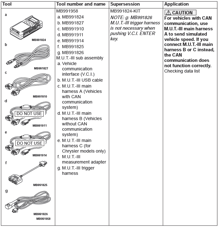
Required Special Tools:
- MB991958: Scan Tool (M.U.T.-III Sub Assembly)
- MB991824: V.C.I.
- MB991827: M.U.T.-III USB Cable
- MB991910: M.U.T.-III Main Harness A
CAUTION
If there is any problem in the CAN bus lines, an incorrect DTC may be set. Prior to this diagnosis, diagnose the CAN bus lines.
STEP 1. Using scan tool MB991958, diagnose the CAN bus line.
CAUTION
To prevent damage to scan tool MB991958, always turn the ignition switch to the "LOCK" (OFF) position before connecting or disconnecting scan tool MB991958.
- Connect scan tool MB991958 to the data link connector.
- Turn the ignition switch to the "ON" position.
- Set scan tool MB991958 to diagnose the CAN bus line.
Q: Is the check result satisfactory?
YES : Go to Step 2.
NO : Repair the CAN bus lines.
Then go to Step 4.
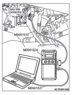
STEP 2. Using scan tool MB991958, check the data list item 74: Brake light switch, item 89: Normally closed brake switch.
- Connect scan tool MB991958 to the data link connector.
- Turn the ignition switch to the "ON" position.
- Set scan tool MB991958 to data reading mode for cruise control system.
- Item 74: Brake light switch.
- When the brake pedal is depressed, the display on scan tool MB991958 should be "ON".
- When the brake pedal is released, the display on scan tool MB991958 should be "OFF".
- Item 89: Normally closed brake switch.
- When the brake pedal is depressed, the display on scan tool MB991958 should be "ON".
- When the brake pedal is released, the display on scan tool MB991958 should be "OFF".
Q: Is the switch operating properly?
YES : Go to Step 3.
NO : Repair the stoplight switch system. Then go to Step 4.
STEP 3. Check the symptom.
Q: When the brake pedal is depressed, is the cruise control cancelled?
YES : It can be assumed that this malfunction is intermittent (Refer to GROUP 00, How to Use Troubleshooting/Inspection Service Points − How to Cope with Intermittent Malfunctions).
NO : Replace the ECM [Refer to GROUP 13A, Engine Control Module (ECM) ] <2.4L Engine> or [Refer to GROUP 13B, Engine Control Module (ECM) ] <3.0L Engine>. Then go to Step 4.
STEP 4. Check the symptom.
Q: When the brake pedal is depressed, is the cruise control cancelled?
YES : The procedure is complete.
NO : Return to Step 1.
Inspection Procedure 2: When the Selector Lever is Moved to "N" Position, cruise Control System is not Cancelled.
CIRCUIT OPERATION
When the selector lever is operated, the selector lever position signal from the transmission range switch is sent to the TCM. ECM receives the selector lever position signal from the TCM via the CAN bus line.
COMMENT
- Malfunction of CAN bus line.
- Malfunction of CVT system <2.4L Engine> or A/T system <3.0L Engine>.
- The transmission range switch circuit is suspected.
TROUBLESHOOTING HINTS (THE MOST LIKELY CAUSES FOR THIS CASE:)
- Malfunction of CAN bus system.
- Damaged harness or connector.
- Malfunction of CVT system <2.4L Engine>.
- Malfunction of A/T system <3.0L Engine>.
- Malfunction of the transmission range switch.
- Malfunction of the TCM.
- Malfunction of the ECM.
DIAGNOSTIC PROCEDURE
Required Special Tools:
- MB991958: Scan Tool (M.U.T.-III Sub Assembly)
- MB991824: V.C.I.
- MB991827: M.U.T.-III USB Cable
- MB991910: M.U.T.-III Main Harness A
CAUTION If there is any problem in the CAN bus lines, an incorrect DTC may be set. Prior to this diagnosis, diagnose the CAN bus lines.
STEP 1. Using scan tool MB991958, diagnose the CAN bus line.
CAUTION To prevent damage to scan tool MB991958, always turn the ignition switch to the "LOCK" (OFF) position before connecting or disconnecting scan tool MB991958.
- Connect scan tool MB991958 to the data link connector.
- Turn the ignition switch to the "ON" position.
- Set scan tool MB991958 to diagnose the CAN bus line.
Q: Is the check result satisfactory?
YES : Go to Step 2 <2.4L Engine>.
YES : Go to Step 4 <3.0L Engine>.
NO : Repair the CAN bus lines.
Then go to Step 8.
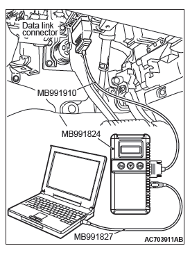
STEP 2. Using scan tool MB991958, check the CVT system data list item 49: Transmission range switch <2.4L Engine>.
- Connect scan tool MB991958 to the data link connector.
- Turn the ignition switch to the "ON" position.
- Set scan tool MB991958 to data reading mode for CVT system.
- Item 49: Transmission range switch.
Q: Is the switch operating properly?
YES : Go to Step 3.
NO : Repair the CVT system (Refer to GROUP 23A, Diagnosis, Diagnostic Trouble Code Procedures − DTC P0705: Malfunction of Transmission Range Switch.) Then go to Step 8.
STEP 3. Using scan tool MB991958, read the CVT system DTC <2.4L Engine>.
- Connect scan tool MB991958 to the data link connector.
- Turn the ignition switch to the "ON" position.
- Set scan tool MB991958 to check for CVT system DTC.
Q: Is any DTC set?
YES : Diagnose the CVT system. Then go to Step 8.
NO : Go to Step 6.
STEP 4. Using scan tool MB991958, check the A/T system data list item 54: Transmission range switch <3.0L Engine>.
- Connect scan tool MB991958 to the data link connector.
- Turn the ignition switch to the "ON" position.
- Set scan tool MB991958 to data reading mode for A/T system.
- Item 54: Transmission range switch.
Q: Is the switch operating properly?
YES : Go to Step 5.
NO : Repair the A/T system. Then go to Step 8.
STEP 5. Using scan tool MB991958, read the A/T system DTC <3.0L Engine>.
- Connect scan tool MB991958 to the data link connector.
- Turn the ignition switch to the "ON" position.
- Set scan tool MB991958 to check for A/T system DTC.
Q: Is any DTC set?
YES : Repair the A/T system. Then go to Step 8.
NO : Go to Step 6.
STEP 6. Using scan tool MB991958, check data list item 88: Neutral switch.
- Connect scan tool MB991958 to the data link connector.
- Turn the ignition switch to the "ON" position.
- Set scan tool MB991958 to data reading mode for cruise control system.
- Item 88: Neutral switch.
- When selector lever is at the "P" and "N" position, the display on scan tool MB991958 should be "ON".
- When selector lever is other than "P" and "N" position, the display on scan tool MB991958 should be "OFF".
Q: Is the switch operating properly?
YES : Go to Step 7.
NO : Replace the ECM [Refer to GROUP 13A, Engine Control Module (ECM) ] <2.4L Engine> or [Refer to GROUP 13B, Engine Control Module (ECM) ] <3.0L Engine>. Then go to Step 8.
STEP 7. Check the symptom.
Q: When the selector lever is moved to "N" position, is the cruise control cancelled?
YES : It can be assumed that this malfunction is intermittent (Refer to GROUP 00, How to Use Troubleshooting/Inspection Service Points − How to Cope with Intermittent Malfunctions).
NO : Replace the ECM [Refer to GROUP 13A, Engine Control Module (ECM) ] <2.4L Engine> or [Refer to GROUP 13B, Engine Control Module (ECM) ] <3.0L Engine>. Then go to Step 8.
STEP 8. Check the symptom.
Q: When the selector lever is moved to "N" position, is the cruise control cancelled?
YES : The procedure is complete.
NO : Return to Step 1.
Inspection Procedure 3: When the "CANCEL" Switch is Set to ON, Cruise Control System is not Cancelled.
COMMENT
The cause is probably an open-circuit in the output circuit inside the "CANCEL" switch.
TROUBLESHOOTING HINTS (THE MOST LIKELY CAUSES FOR THIS CASE:)
- Malfunction of the cruise control switch.
- Malfunction of the ECM.
DIAGNOSTIC PROCEDURE
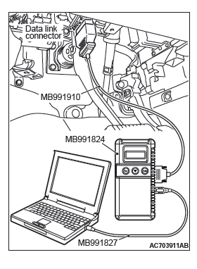
Required Special Tools:
- MB991958: Scan Tool (M.U.T.-III Sub Assembly)
- MB991824: V.C.I.
- MB991827: M.U.T.-III USB Cable
- MB991910: M.U.T.-III Main Harness A
STEP 1. Using scan tool MB991958, check the data list item 75: Cancel switch.
CAUTION To prevent damage to scan tool MB991958, always turn the ignition switch to the "LOCK" (OFF) position before connecting or disconnecting scan tool MB991958.
- Connect scan tool MB991958 to the data link connector.
- Turn the ignition switch to the "ON" position.
- Set scan tool MB991958 to data reading mode for cruise control system.
- Item 75: Cancel switch.
- When the "CANCEL" switch is pressed, the display on scan tool MB991958 should be "ON".
- When the "CANCEL" switch is released, the display on scan tool MB991958 should be "OFF".
Q: Is the switch operating properly?
YES : Go to Step 2.
NO : Repair the cruise control switch system. Then go to Step 3.
STEP 2. Check the symptom.
Q: When the "CANCEL" switch is pressed, is the cruise control cancelled?
YES : It can be assumed that this malfunction is intermittent (Refer to GROUP 00, How to Use Troubleshooting/Inspection Service Points − How to Cope with Intermittent Malfunctions).
NO : Replace the ECM [Refer to GROUP 13A, Engine Control Module (ECM) ] <2.4L Engine> or [Refer to GROUP 13B, Engine Control Module (ECM) ] <3.0L Engine>. Then go to Step 3.
STEP 3. Check the symptom.
Q: When the "CANCEL" switch is pressed, is the cruise control cancelled?
YES : The procedure is complete.
NO : Return to Step 1.
Inspection Procedure 4: Cruise Control cannot be Set (No Response "COAST/SET" Switch and "ACC/RES" Switch is Pressed).
COMMENT
The fail-safe function is probably canceling cruise control system. In this case, checking the cruise control system, MFI system, CVT system <2.4L Engine> or A/T system <3.0L Engine>, ASC system <vehicles with ASC> and CAN bus line system for DTCs. The scan tool MB991958 can also be used to check if the circuits of each input switch are normal or not by checking the data list.
NOTE: Press the cruise control switches one by one securely. Otherwise, the cruise control system may not be started.
TROUBLESHOOTING HINTS (THE MOST LIKELY CAUSES FOR THIS CASE:)
- Malfunction of the CAN bus line system.
- Malfunction of the MFI system.
- Malfunction of the CVT system <2.4L Engine>.
- Malfunction of the A/T system<3.0L Engine>.
- Malfunction of the ASC system <vehicles with ASC>.
- Malfunction of the cruise control switch.
- Malfunction of the stoplight switch.
- Malfunction of the transmission range switch.
- Malfunction of the TCM.
- Malfunction of the ECM.
DIAGNOSTIC PROCEDURE
Required Special Tools:
- MB991958: Scan Tool (M.U.T.-III Sub Assembly)
- MB991824: V.C.I.
- MB991827: M.U.T.-III USB Cable
- MB991910: M.U.T.-III Main Harness A
CAUTION If there is any problem in the CAN bus lines, an incorrect DTC may be set. Prior to this diagnosis, diagnose the CAN bus lines.
STEP 1. Using scan tool MB991958, diagnose the CAN bus line.
CAUTION To prevent damage to scan tool MB991958, always turn the ignition switch to the "LOCK" (OFF) position before connecting or disconnecting scan tool MB991958.
- Connect scan tool MB991958 to the data link connector.
- Turn the ignition switch to the "ON" position.
- Set scan tool MB991958 to diagnose the CAN bus line.
Q: Is the check result satisfactory?
YES : Go to Step 2.
NO : Repair the CAN bus lines.
Then go to Step 12.
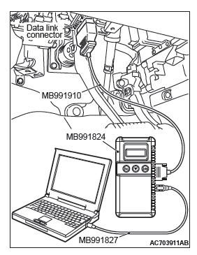
STEP 2. Using scan tool MB991958, check for ECM option coding data.
- Connect scan tool MB991958 to the data link connector.
- Turn the ignition switch to the "ON" position.
- Check for ECM option coding data.
Q: Is the cruise control item of the ECM option coding data enabled?
YES : Go to Step 3.
NO : Set the ECM option coding data again. Then go to Step 12.
STEP 3. Using scan tool MB991958, read the MFI system DTC.
- Connect scan tool MB991958 to the data link connector.
- Turn the ignition switch to the "ON" position.
- Set scan tool MB991958 to check for MFI system DTC (Refer to GROUP 13A, MFI Diagnosis − Diagnostic Function) <2.4L Engine> or (Refer to GROUP 13B, MFI Diagnosis − Diagnostic Function) <3.0L Engine>.
Q: Is any DTC set?
YES : Repair the MFI system (Refer to GROUP 13A, MFI Diagnosis − Diagnostic Trouble Code Chart) <2.4L Engine> or (Refer to GROUP 13B, MFI Diagnosis − Diagnostic Trouble Code Chart) <3.0L Engine>. Then go to Step 12.
NO : Go to Step 4 <2.4L Engine>.
NO : Go to Step 5 <3.0L Engine>.
STEP 4. Using scan tool MB991958, read the CVT system DTC <2.4L Engine>.
- Connect scan tool MB991958 to the data link connector.
- Turn the ignition switch to the "ON" position.
- Set scan tool MB991958 to check for CVT system DTC.
Q: Is any DTC set?
YES : Repair the CVT system. Then go to Step 12.
NO : Go to Step 6.
STEP 5. Using scan tool MB991958, read the A/T system DTC <3.0L Engine>.
- Connect scan tool MB991958 to the data link connector.
- Turn the ignition switch to the "ON" position.
- Set scan tool MB991958 to check for A/T system DTC.
Q: Is any DTC set?
YES : Repair the A/T system. Then go to Step 12.
NO : Go to Step 6 <vehicles with ASC>.
NO : Go to Step 7 <vehicles without ASC>.
STEP 6. Using scan tool MB991958, read for ASC system DTC <vehicles with ASC>.
- Connect scan tool MB991958 to the data link connector.
- Turn the ignition switch to the "ON" position.
- Set scan tool MB991958 to check for ASC system DTC.
Q: Is any DTC set?
YES : Repair the ASC system. Then go to Step 12.
NO : Go to Step 7.
STEP 7. Read the cruise control system DTC.
- Disconnect the negative (−) battery terminal, to erase the DTC of the cruise control system.
- Connect the negative (−) battery terminal.
- Turn the ignition switch to the "ON" position, and press the "ON/OFF" switch to turn the cruise control system to ON (turn on the "CRUISE" indicator light).
- After turning the cruise control system to ON, when 2 minutes or more has elapsed without operating the cruise control switches, read the DTC of the cruise control system.
Q: Is any DTC set?
YES : Repair the cruise control system. Then go to Step 12.
NO : Go to Step 8.
STEP 8. Using scan tool MB991958, check the data list item 75: Cancel switch, item 86: Main switch, item 91: Resume switch and item 92: Set switch.
- Connect scan tool MB991958 to the data link connector.
- Turn the ignition switch to the "ON" position.
- Set scan tool MB991958 to data reading mode for cruise control system.
- Item 75: Cancel switch.
- When "CANCEL" switch is pressed, the display on scan tool MB991958 should be "ON".
- When "CANCEL" switch is released, the display on scan tool MB991958 should be "OFF".
- Item 86: Main switch.
- When "ON/OFF" switch is pressed, the display on scan tool MB991958 should be "ON".
- When "ON/OFF" switch is pressed again, the display on scan tool MB991958 should be "OFF".
- Item 91: Resume switch.
- When "ACC/RES" switch is pressed, the display on scan tool MB991958 should be "ON".
- When "ACC/RES" switch is released, the display on scan tool MB991958 should be "OFF".
- Item 92: Set switch.
- When "COAST/SET" switch is pressed, the display on scan tool MB991958 should be "ON".
- When "COAST/SET" switch is released, the display on scan tool MB991958 should be "OFF".
Q: Is the switch operating properly?
YES : Go to Step 9.
NO : Repair the cruise control switch system. Then go to Step 12.
STEP 9. Using scan tool MB991958, check the data list item 74: Brake light switch, item 89: Normally closed brake switch.
- Connect scan tool MB991958 to the data link connector.
- Turn the ignition switch to the "ON" position.
- Set scan tool MB991958 to data reading mode for cruise control system.
- Item 74: Brake light switch.
- When the brake pedal is depressed, the display on scan tool MB991958 should be "ON".
- When the brake pedal is released, the display on scan tool MB991958 should be "OFF".
- Item 89: Normally closed brake switch.
- When the brake pedal is depressed, the display on scan tool MB991958 should be "ON".
- When the brake pedal is released, the display on scan tool MB991958 should be "OFF".
Q: Is the switch operating properly?
YES : Go to Step 10.
NO : Repair the stoplight switch system. Then go to Step 12.
STEP 10. Using scan tool MB991958, check the data list item 88: Neutral switch.
- Connect scan tool MB991958 to the data link connector.
- Turn the ignition switch to the "ON" position.
- Set scan tool MB991958 to data reading mode for cruise control system.
- Item 88: Neutral switch.
- When the selector lever is moved to "N" or "P" position, the display on scan tool MB991958 should be "ON".
- When the selector lever is moved to other than "N" or "P" position, the display on scan tool MB991958 should be "OFF".
Q: Is the switch operating properly?
YES : Go to Step 11.
NO : Repair the CVT system (Refer to GROUP 23A, Diagnosis − Diagnostic Trouble Code Procedures − DTC P0705: Malfunction of Transmission Range Switch) <2.4L Engine> or A/T system (Refer to GROUP 23C, Automatic Transaxle Diagnosis − Diagnostic Trouble Code Procedures − DTC P0705: Transmission Range Switch System) <3.0L Engine>. Then go to Step 12.
STEP 11. Check the symptom.
Q: Can cruise control be set?
YES : It can be assumed that this malfunction is intermittent (Refer to GROUP 00, How to Use Troubleshooting/Inspection Service Points − How to Cope with Intermittent Malfunction).
NO : Replace the ECM [Refer to GROUP 13A, Engine Control Module (ECM) ] <2.4L Engine> or [Refer to GROUP 13B, Engine Control Module (ECM) ] <3.0L Engine>. Then go to Step 12.
STEP 12. Check the symptom.
Q: Can auto-cruise control be set?
YES : The procedure is complete.
NO : Return to Step 1.
Inspection Procedure 5: Hunting (Repeated Acceleration and Deceleration) Occurs at the Set Vehicle Speed.
COMMENT
- The secondary pulley speed sensor signal (vehicle speed signal) <2.4L Engine>, output shaft speed sensor signal (vehicle speed signal) <3.0L Engine>, or the throttle body is suspected.
- The secondary pulley speed sensor signal (vehicle speed signal) <2.4L Engine> or output shaft speed sensor signal (vehicle speed signal) <3.0L Engine> is transmitted from the TCM to the ECM via the CAN bus line.
NOTE: When the vehicle is driven with the low-speed gear in the sport mode, hunting occurs easily, however, this is not a failure.
TROUBLESHOOTING HINTS (THE MOST LIKELY CAUSES FOR THIS CASE:)
- Malfunction of the CAN bus line system.
- Malfunction of the secondary pulley speed sensor <2.4L Engine>.
- Malfunction of the output shaft speed sensor <3.0L Engine>.
- Malfunction of the CVT system <2.4L Engine>.
- Malfunction of the A/T system <3.0L Engine>.
- Malfunction of the throttle body.
- Malfunction of the ECM.
DIAGNOSTIC PROCEDURE
Required Special Tools:
- MB991958: Scan Tool (M.U.T.-III Sub Assembly)
- MB991824: V.C.I.
- MB991827: M.U.T.-III USB Cable
- MB991910: M.U.T.-III Main Harness A
CAUTION If there is any problem in the CAN bus lines, an incorrect diagnostic trouble code (DTC) may be set. Prior to this diagnosis, diagnose the CAN bus lines.
STEP 1. Using scan tool MB991958, diagnose the CAN bus line.
CAUTION To prevent damage to scan tool MB991958, always turn the ignition switch to the "LOCK" (OFF) position before connecting or disconnecting scan tool MB991958.
- Connect scan tool MB991958 to the data link connector.
- Turn the ignition switch to the "ON" position.
- Set scan tool MB991958 to diagnose the CAN bus line.
Q: Is the check result satisfactory?
YES : Go to Step 2 <2.4L Engine>.
YES : Go to Step 3 <3.0L Engine>.
NO : Repair the CAN bus lines.
Then go to Step 7.
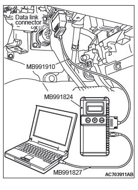
STEP 2. Using scan tool MB991958, read the CVT system DTC <2.4L Engine>.
- Connect scan tool MB991958 to the data link connector.
- Turn the ignition switch to the "ON" position.
- Set scan tool MB991958 to check for CVT system DTC.
Q: Is any DTC set?
YES : Repair the CVT system. Then go to Step 7.
NO : Go to Step 4.
STEP 3. Using scan tool MB991958, read the A/T system DTC <3.0L Engine>.
- Connect scan tool MB991958 to the data link connector.
- Turn the ignition switch to the "ON" position.
- Set scan tool MB991958 to check for A/T system DTC.
Q: Is any DTC set?
YES : Repair the A/T system. Then go to Step 7.
NO : Go to Step 4.
STEP 4. Using scan tool MB991958, read the MFI system DTC.
- Connect scan tool MB991958 to the data link connector.
- Turn the ignition switch to the "ON" position.
- Set scan tool MB991958 to check for MFI system DTC(Refer to GROUP 13A, MFI Diagnosis − DiagnosticFunction) <2.4L Engine> or (Refer to GROUP13B, MFI Diagnosis − Diagnostic Function) <3.0LEngine>.
Q: Is any DTC set?
YES : Repair the MFI system. Then go to Step 7.
NO : Go to Step 5.
STEP 5. Using scan tool MB991958, check the data list item 4: vehicle speed signal.
- Connect scan tool MB991958 to the data link connector.
- Turn the ignition switch to the "ON" position.
- Set scan tool MB991958 to data reading mode for cruise control system.
- Item 4: Vehicle speed signal.
- When road test the vehicles, check the display on scan tool MB991958 and speedometer.
Q: Is the check result satisfactory?
YES : Go to Step 6.
NO : Replace the ECM [Refer to GROUP 13A, Engine Control Module (ECM) ] <2.4L Engine> or [Refer to GROUP 13B, Engine Control Module (ECM) ] <3.0L Engine>. Then go to Step 7.
STEP 6. Check the symptom.
Q: Does hunting occur?
YES : Replace the ECM [Refer to GROUP 13A, Engine Control Module (ECM) ] <2.4L Engine> or [Refer to GROUP 13B, Engine Control Module (ECM) ] <3.0L Engine>. Then go to Step 7.
NO : It can be assumed that this malfunction is intermittent.
STEP 7. Check the symptom.
Q: Does hunting occur?
YES : Return to Step 1.
NO : The procedure is complete.
Inspection Procedure 6: When "ON/OFF" Switch is Turned ON, "CRUISE" Indicator Light Inside Combination Meter does not Illuminate (However, Cruise Control System is Normal).
CIRCUIT OPERATION
- The ECM detects "ON/OFF" switch ON signal to illuminate the "CRUISE" indicator light within the combination meter.
- The "CRUISE" indicator light illuminate signal is transmitted from the ECM to the combination meter via CAN bus line.
COMMENT
- The CAN bus line between the ECM and the ETACS-ECU and between the ETACS-ECU and the combination meter may be defective.
- The combination meter, ETACS-ECU or ECM may also be defective.
TROUBLESHOOTING HINTS
- Malfunction of CAN bus system.
- Damaged harness or connector.
- Malfunction of the combination meter.
- Malfunction of the ETACS-ECU
- Malfunction of the ECM
DIAGNOSTIC PROCEDURE
Required Special Tools:
- MB991958: Scan Tool (M.U.T.-III Sub Assembly)
- MB991824: V.C.I.
- MB991827: M.U.T.-III USB Cable
- MB991910: M.U.T.-III Main Harness A
CAUTION If there is any problem in the CAN bus lines, an incorrect DTC may be set. Prior to this diagnosis, diagnose the CAN bus lines.
STEP 1. Using scan tool MB991958, diagnose the CAN bus line.
CAUTION To prevent damage to scan tool MB991958, always turn the ignition switch to the "LOCK" (OFF) position before connecting or disconnecting scan tool MB991958.
- Connect scan tool MB991958 to the data link connector.
- Turn the ignition switch to the "ON" position.
- Set scan tool MB991958 to diagnose the CAN bus line.
Q: Is the check result satisfactory?
YES : Go to Step 2
NO : Repair the CAN bus lines.
Then go to Step 6.
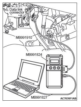
STEP 2. Using scan tool MB991958, read the MFI system DTC.
- Connect scan tool MB991958 to the data link connector.
- Turn the ignition switch to the "ON" position.
- Set scan tool MB991958 to check for MFI system DTC (Refer to GROUP 13A, MFI Diagnosis − Diagnostic Function) <2.4L Engine> or (Refer to GROUP 13B, MFI Diagnosis − Diagnostic Function) <3.0L Engine>.
Q: Is DTC U0141 set?
YES : Repair the MFI system (Refer to GROUP 13A, MFI Diagnosis, Diagnostic Trouble Code Procedures − DTC U0141: ETACS-ECU Time) <2.4L Engine> or (Refer to GROUP 13B, MFI Diagnosis, Diagnostic Trouble Code Procedures − DTC U0141: ETACS-ECU Time Out) <3.0L Engine>. Then go to Step 6.
NO : Go to Step 3.
STEP 3. Using scan tool MB991958, read the ETACS system DTC.
- Connect scan tool MB991958 to the data link connector.
- Turn the ignition switch to the "ON" position.
- Set scan tool MB991958 to check for ETACS system DTC (Refer to GROUP 54A, ETACS, Troubleshooting − Diagnostic Function).
Q: Is DTC U0155 set?
YES : Repair the ETACS system (Refer to GROUP 54A, ETACS, Troubleshooting, Diagnostic Trouble Code Procedures − DTC U0155: Combination Meter-ECU CAN Communication Time Out). Then go to Step 6.
NO : Go to Step 4.
STEP 4. Using scan tool MB991958, check the combination meter system actuator test item 7: Cruise indicator 1.
- Connect scan tool MB991958 to the data link connector.
- Turn the ignition switch to the "ON" position.
- Set scan tool MB991958 to check the actuator test for combination meter system item 7: indicator 1 (Refer to GROUP 54A, Combination Meter, Troubleshooting − Actuator Teat Table)
Q: Is the check result satisfactory?
YES : Go to Step 5.
NO : Repair the combination meter system (Refer to GROUP 54A, Combination Meter, Troubleshooting, Symptom Procedures − Inspection Procedure 5: The combination meter light does not illuminate normally or the multi information display is not displayed normally). Then go to Step 6.
STEP 5. Check the symptom.
Q: When the "ON/OFF" switch is turned ON, is the "CRUISE" indicator light illuminated?
YES : It can be assumed that this malfunction is intermittent (Refer to GROUP 00, How to Use Troubleshooting/Inspection Service Points − How to Cope with Intermittent Malfunctions).
NO : Replace the ECM [Refer to GROUP 13A, Engine Control Module (ECM) ] <2.4L Engine> or [Refer to GROUP 13B, Engine Control Module (ECM) ] <3.0L Engine>. Then go to Step 6.
STEP 6. Check the symptom.
Q: When the "ON/OFF" switch is turned ON, is the "CRUISE" indicator light illuminated?
YES : The procedure is complete.
NO : Return to Step 1.
DATA LIST REFERENCE TABLE
CAUTION
- Driving tests always need two persons: one driver and one observer.
- When shifting the selector lever to "D" range apply the brakes should be applied so that the vehicle does not move forward.
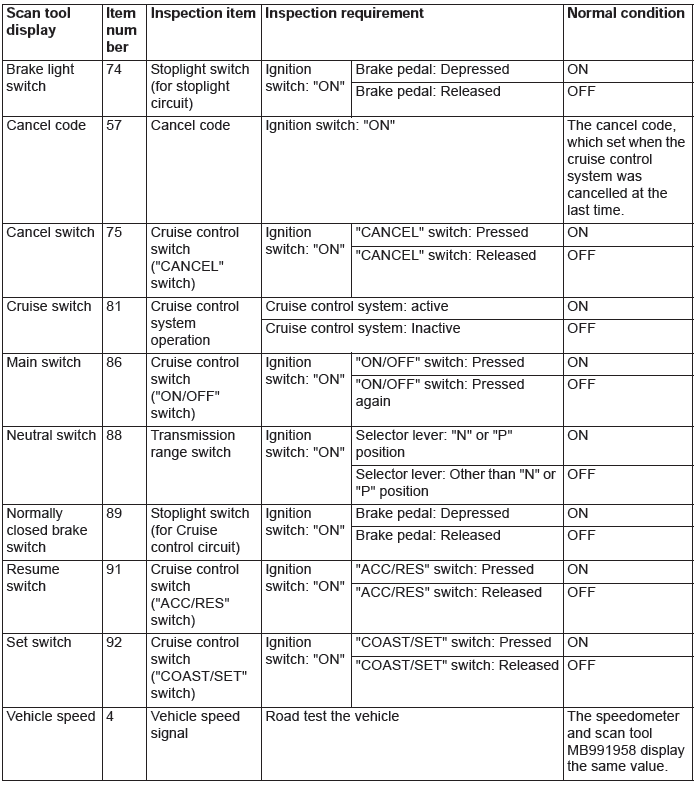
ECM TERMINAL VOLTAGE REFERENCE CHART FOR CRUISE CONTROL SYSTEM OPERATION
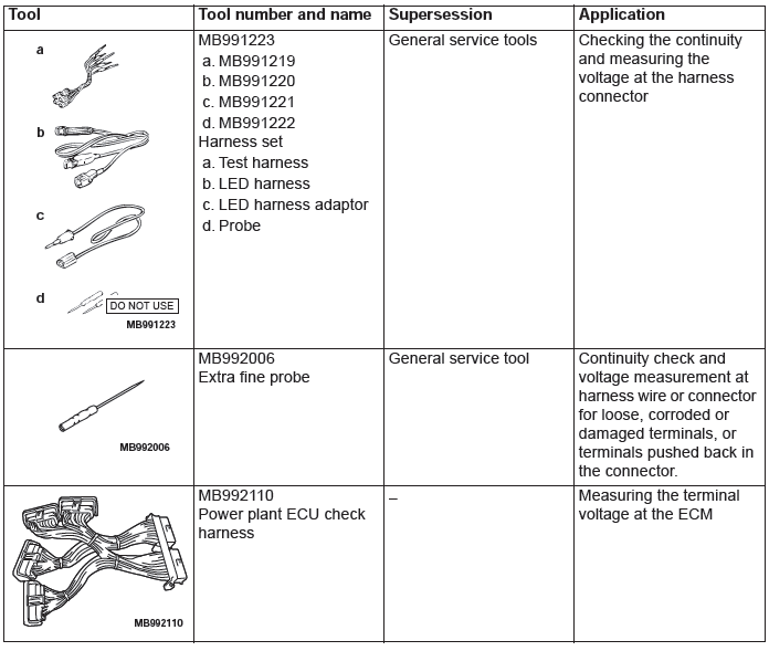
Required Special Tool:
- MB992110: Power plant ECU check harness
Use special tool MB992110, check the ECM terminal voltage.
1. Disconnect the all ECM connectors, and connect special tool (MB992110) in between [Refer to GROUP 13A, Engine Control Module (ECM) ] <2.4L Engine> or [Refer to GROUP 13B, Engine Control Module (ECM) ] <3.0L Engine>.
2. Measure the voltages between the check connector terminals of special tool (MB992044) and ground terminals (ECM connector B-11 terminal 81 or 93).
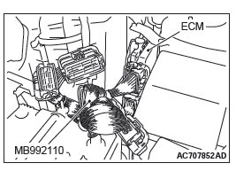
Special tool - Power plant ECU check harness (MB992110) connector: Component side


SPECIAL TOOLS
ON-VEHICLE SERVICE
CRUISE CONTROL SYSTEM OPERATION CHECK
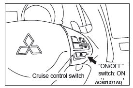
CRUISE CONTROL "ON/OFF" SWITCH CHECK
1. Turn the ignition switch to the "ON" position.
2. Check that the "CRUISE" indicator light within the combination meter illuminates when the "ON/OFF" switch is pressed (cruise control system: ON).
3. Press the "ON/OFF" switch again (cruise control system: OFF), and check that the "CRUISE" indicator light within the combination meter goes out.
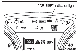
CRUISE CONTROL SETTING
1. Start the engine.
2. Press the "ON/OFF" switch (cruise control system: ON, "CRUISE" indicator light: illuminated).
3. Drive at the desired speed, above approximately 40 km/h (25 mph).
4. Press the "COAST/SET" switch.
5. Check to be sure that when the "COAST/SET" switch is released the speed is the constant speed.
NOTE: If the vehicle speed decreases to approximately 15 km/h (9 mph) below the set speed because of climbing a hill for example, it is normal for the cruise control to be cancelled.
When the vehicle speed becomes low-speed limit [approximately 40 km/h (25 mph) ] or less, driving at constant speed will be cancelled even if the vehicle speed does not decrease 15 km/h (9 mph) or more.
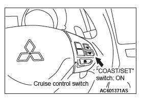
SPEED-INCREASE SETTING
1. Start the engine.
2. Press the "ON/OFF" switch (cruise control system: ON, "CRUISE" indicator light: illuminated).
3. Set to the desired speed, above approximately 40 km/h (25 mph).
4. Press the "ACC/RES" switch.
5. Check to be sure that acceleration continues while the "ACC/RES" switch is pressed, and that the speed at the time it was released becomes the constant driving speed.
NOTE: Acceleration can be continued even if the vehicle speed has passed the high-speed limit [approximately 160 km/h (100 mph) ]. But the constant driving speed when the "ACC/RES" switch is released will be recorded as the high-speed limit.
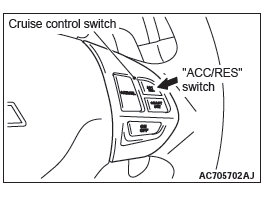
SPEED-REDUCTION SETTING
1. Start the engine.
2. Press the "ON/OFF" switch (cruise control system: ON, "CRUISE" indicator light: illuminated).
3. Set to the desired speed, above approximately 40 km/h (25 mph).
4. Press the "COAST/SET" switch.
5. Check to be sure that deceleration continues while the "COAST/SET" switch is pressed, and that the speed at the time it was released becomes the constant driving speed.
NOTE: When the vehicle speed reaches the low limit [approximately 40 km/h (25 mph) ] during deceleration, the cruise control will be cancelled.
RETURN TO THE SET SPEED BEFORE CANCELLATION AND CRUISE CONTROL CANCELLATION
1. Start the engine.
2. Press the "ON/OFF" switch (cruise control system: ON, "CRUISE" indicator light: illuminated).
3. Set to the desired speed, above approximately 40 km/h (25 mph).
4. When any of the following operations are performed while at constant speed during cruise control, check if normal driving is resumed and deceleration occurs.
- The "CANCEL" switch is pressed.
- The brake pedal is depressed.
5. At a vehicle speed of approximately 40 km/h (25 mph) or higher, check if when the "ACC/RES" switch is pressed, the vehicle speed returns to the speed before cruise control driving was cancelled, and constant speed driving occurs.
6. When the "ON/OFF" switch is pressed again (cruise control system: OFF) while driving at constant speed, check if normal driving is resumed and deceleration occurs.
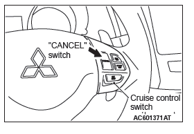
CRUISE CONTROL SYSTEM COMPONENT CHECK
CRUISE CONTROL SWITCH CHECK
1. Remove the cruise control switch.
2. Measure the resistance between terminal number 2 and terminal number 3 when each of the "ON/OFF", "CANCEL", "COAST/SET" and "ACC/RES" switches is pressed. If the values measured at the time each switch is pressed correspond to those in the table below, the resistance values are correct.
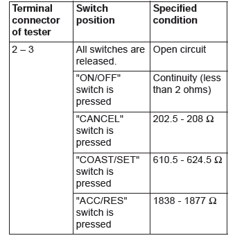
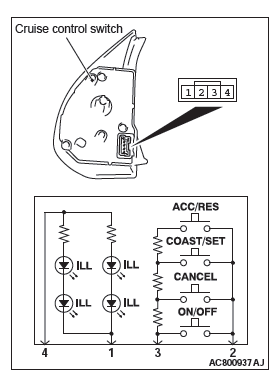
3. Check that the cruise control switch illuminates when a positive battery terminal is connected to the connector terminal number 4, and terminal number 1 is grounded.
STOPLIGHT SWITCH CHECK
Refer to GROUP 35A, Brake Pedal, Inspection − Stoplight Switch Check.
TRANSMISSION RANGE SWITCH CHECK
Refer to GROUP 23A, On-vehicle Service − Essential Service <2.4L Engine>.
Refer to GROUP 23C, On-vehicle Service − Essential Service <3.0L Engine>.
THROTTLE ACTUATOR CONTROL MOTOR CHECK
Refer to GROUP 13A, On-vehicle Service − Throttle Actuator Control Motor Check <2.4L Engine>.
Refer to GROUP 13B, On-vehicle Service − Throttle Actuator Control Motor Check <3.0L Engine>.
CRUISE CONTROL SWITCH
REMOVAL AND INSTALLATION
WARNING
Before removing the driver's air bag module assembly, refer to GROUP 52B, Service Precautions and Driver's Air Bag Module and Clock Spring.
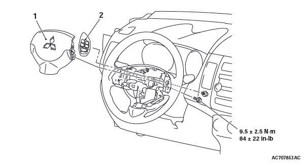
Removal steps
- Driver's air bag module
- Cruise control switch

