Mitsubishi Outlander: Emission Control MFI
GENERAL INFORMATION
The emission control system consists of the following subsystems:
- Positive crankcase ventilation system
- Evaporative emission system
- Exhaust emission control system
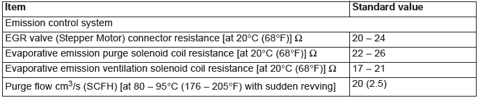
SERVICE SPECIFICATIONS
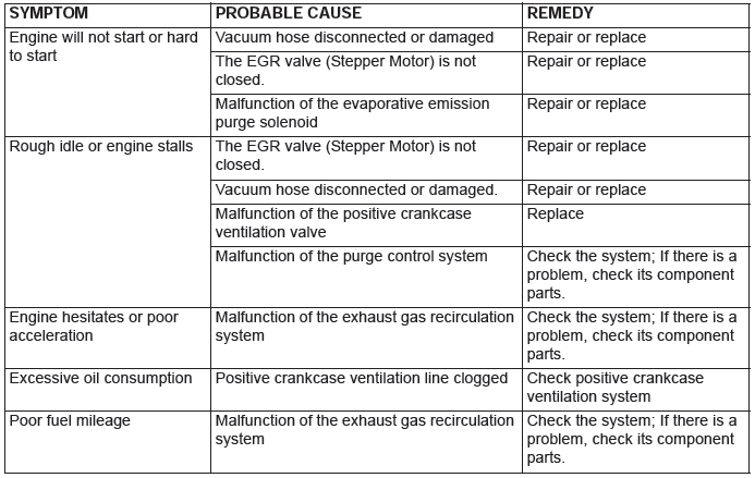
DIAGNOSIS
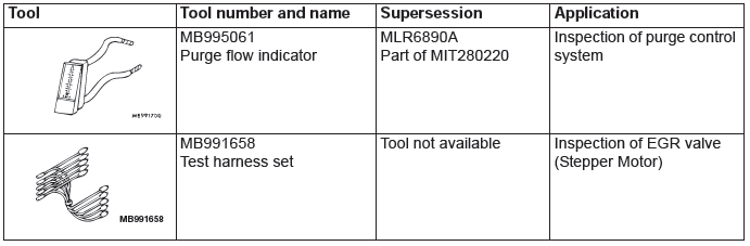
SPECIAL TOOLS
VACUUM HOSES
VACUUM HOSE ROUTING
<2.4L Engine>
<3.0L Engine>
VACUUM CIRCUIT DIAGRAM
<2.4L Engine>
<3.0 Engine>
VACUUM HOSE INSTALLATION
1. When connecting the vacuum hoses, they should be securely inserted onto the nipples.
2. Connect the hoses correctly, using the VACUUM HOSE ROUTING diagram as a guide.
VACUUM HOSE CHECK
1. Using the VACUUM HOSE ROUTING diagram as a guide, check that the vacuum hoses are correctly connected.
2. Check the connection condition of the vacuum hoses which can be removed, loosened, clogged possibly. And then check whether there are no folded and damaged vacuum hoses.
POSITIVE CRANKCASE VENTILATION SYSTEM
GENERAL INFORMATION (POSITIVE CRANKCASE VENTILATION SYSTEM)
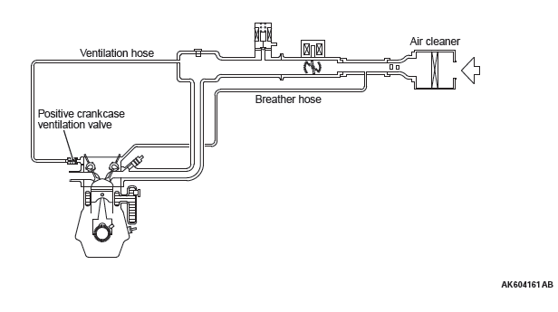
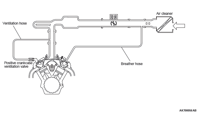
The positive crankcase ventilation (PCV) system prevents the escape of blow-by gases from inside the crankcase into the atmosphere.
Fresh air is sent from the air cleaner into the crankcase through the breather hose to be mixed with the blow-by gas inside the crankcase.
The blow-by gas inside the crankcase is drawn into the intake manifold through the PCV valve.
The PCV valve is designed to lift the plunger according to the intake manifold vacuum so as to regulate the flow of blow-by gas properly.
In other words, the blow-by gas flow is regulated during low load engine operation to maintain engine stability, while the flow is increased during high load operation to improve the ventilation performance.
SYSTEM DIAGRAM
<2.4L Engine>
<3.0L Engine>
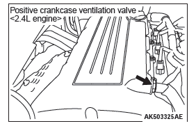
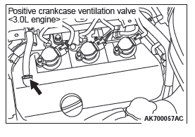
COMPONENT LOCATION
POSITIVE CRANKCASE VENTILATION (PCV) SYSTEM CHECK
1. Remove the ventilation hose from the positive crankcase ventilation (PCV) valve.
2. Remove the PCV valve from the rocker cover.
3. Reinstall the PCV valve at the ventilation hose.
4. Start the engine and run at idle.
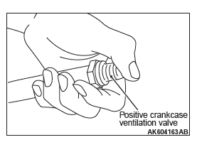
5. Place a finger at the opening of the PCV valve and check that vacuum of the intake manifold is felt.
NOTE: At this moment, the plunger in the PCV valve moves back and forth.
6. If vacuum is not felt, clean the PCV valve or replace it.
7. Apply a small amount of new engine oil to the O-ring on the PCV valve, and tighten to the specified torque.
Specified torque: 2.5 +- 0.4 N*m (22 +- 3 in-lb)
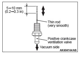
POSITIVE CRANKCASE VENTILATION (PCV) SYSTEM CHECK
1. Remove the ventilation hose from the positive crankcase ventilation (PCV) valve.
2. Remove the PCV valve from the rocker cover.
3. Hold the PCV valve with the vacuum side down. Insert a thin rod, and using light pressure, depress the end of the PCV valve spring by 5 − 10 mm (0.2 − 0.3 inch). Release pressure on the rod to see if the PCV valve spring will lift the rod to its original position.
4. If the rod returns quickly to its original position, the PCV valve is OK. If the stick does not return quickly, clean or replace the PCV valve.
5. Apply a small amount of new engine oil to the O-ring on the PCV valve, and tighten to the specified torque.
Specified torque: 2.5 +- 0.4 N*m (22 +- 3 in-lb)
EVAPORATIVE EMISSION CONTROL SYSTEM
GENERAL INFORMATION (EVAPORATIVE EMISSION SYSTEM)
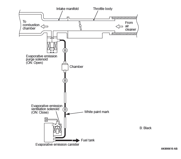
The evaporative emission (EVAP) system prevents fuel vapors generated in the fuel tank from escaping into the atmosphere.
Fuel vapors from the fuel tank flow through the vapor pipe/hose to be stored temporarily in the EVAP canister.
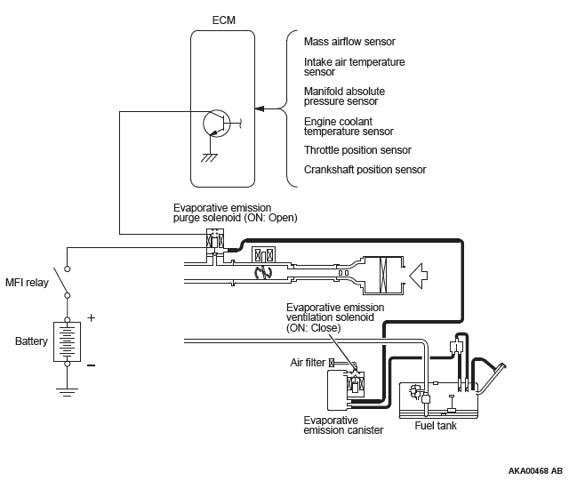
When the vehicle is in operation, fuel vapors stored in the EVAP canister flow through the EVAP purge solenoid, purge port and intake manifold plenum to the combustion chamber.
When the engine coolant temperature is low or when the intake air quantity is small (when the engine is at idle, for example), the engine control module (ECM) brings the EVAP purge solenoid into the OFF state to shut off the fuel vapor flow to the intake manifold plenum.
This ensures driveability when the engine is cold or running under low load and also stabilizes the emission level.
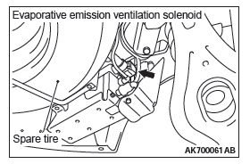
An EVAP ventilation solenoid is provided between the EVAP canister and atmosphere to monitor for OBD-II EVAP leaks. This solenoid is normally OFF.
However, it turns ON when monitoring the OBD-II EVAP leaks and shuts off the atmosphere flow to the EVAP canister. Then the fuel tank differential pressure sensor monitors the fuel vapor pressure to detect OBD-II EVAP leaks.
When the fuel tank inner pressure increases due to the fuel supply, air is released to the atmosphere from the fuel tank through the EVAP canister and air filter. When the inner pressure of the fuel tank decreases, air is supplied to the fuel tank through the air filter and EVAP canister.
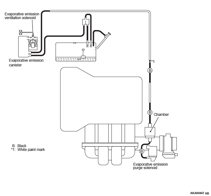
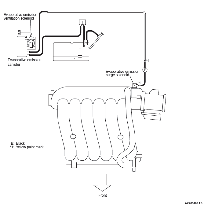
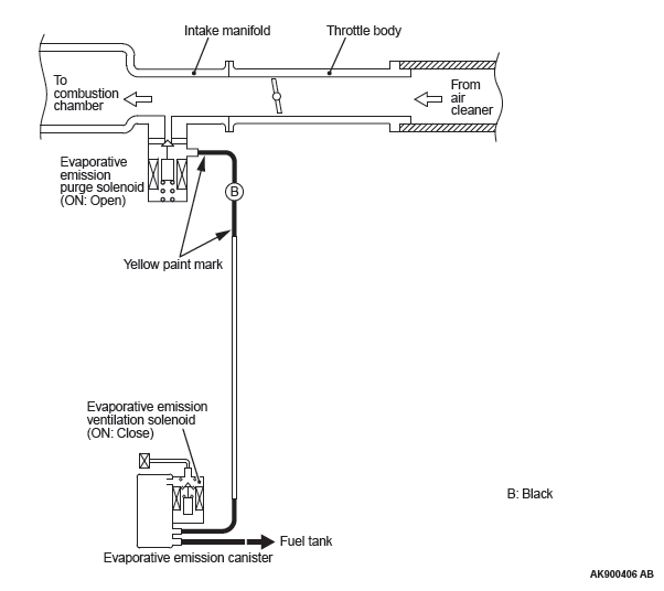
SYSTEM DIAGRAM
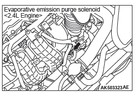
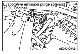
COMPONENT LOCATION
PURGE CONTROL SYSTEM CHECK (PURGE FLOW CHECK)
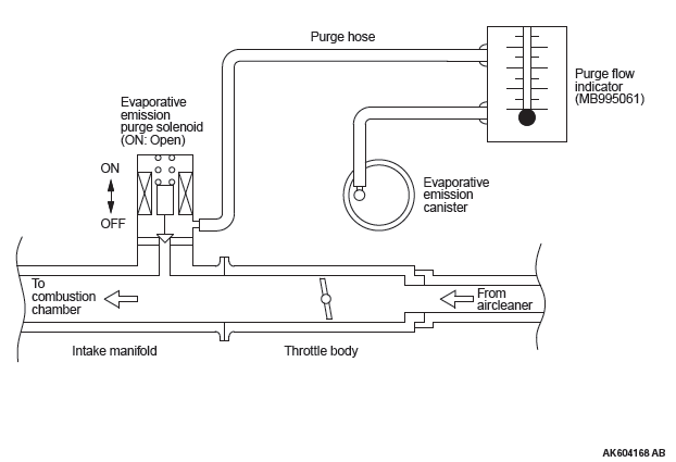
Required Special Tool: MB995061: Purge Flow Indicator
1. Disconnect the purge hose from the evaporative emission (EVAP) purge solenoid, and connect special tool MB995061 between the EVAP purge solenoid and the purge hose.
2. Before inspection, set the vehicle in the following conditions:
- Engine coolant temperature: 80 − 95ºC (176 − 203ºF)
- Lights, electric cooling fan and accessories: OFF
- Transaxle: P range
NOTE: Vehicles for Canada, the headlight, taillight, etc.remain lit even when the lighting switch is in "OFF" position but this is no problem for checks.
3. Run the engine at idle for more than four minutes.
4. Check the purge flow volume when engine is revved suddenly several times.
Standard value: Momentarily 20 cm3/s (2.5 SCFH) or more.
5. If the purge flow volume is less than the standard value, check it again with the vacuum hose disconnected from the EVAP canister. If the purge flow volume is less than the standard value, check the vacuum port and the vacuum hose for clogging. Also check the EVAP purge solenoid. If the purge flow volume is at the standard value, replace the EVAP canister.
EVAPORATIVE EMISSION PURGE SOLENOID CHECK
1. Disconnect the vacuum hose from the evaporative emission (EVAP) purge solenoid.
2. Disconnect the harness connector.
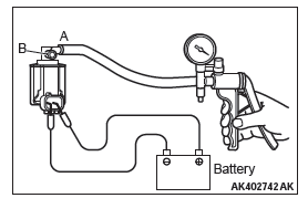
3. Connect a hand vacuum pump to nipple (A) of the EVAP purge solenoid (refer to the illustration at left).
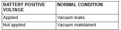
4. As described in the chart below, check airtightness by applying a vacuum with voltage applied directly from the battery to the EVAP purge solenoid valve and without applying voltage.
5. Measure the resistance between the terminals of the EVAP purge solenoid.
Standard value: 22 − 26 Ω [at 20ºC (68ºF) ]
6. Replace the solenoid if resistance is out of specification.
MASS AIRFLOW SENSOR CHECK
<2.4L Engine>
To inspect these parts, refer to GROUP 13A, Multiport Fuel Injection (MFI) <2.4L Engine> − Multiport Fuel Injection (MFI) Diagnosis − Diagnostic Trouble Code Chart.
<3.0L Engine>
To inspect these parts, refer to GROUP 13B, Multiport Fuel Injection (MFI) <3.0L Engine> − Multiport Fuel Injection (MFI) Diagnosis − Diagnostic Trouble Code Chart.
BAROMETRIC PRESSURE SENSOR CHECK
<2.4L Engine>
To inspect the sensor, refer to GROUP 13A, Multiport Fuel Injection (MFI) <2.4L Engine> − Multiport Fuel Injection (MFI) Diagnosis − Diagnostic Trouble Code Chart.
<3.0L Engine>
To inspect the sensor, refer to GROUP 13B, Multiport Fuel Injection (MFI) <3.0L Engine> − Multiport Fuel Injection (MFI) Diagnosis − Diagnostic Trouble Code Chart.
ENGINE COOLANT TEMPERATURE SENSOR CHECK
<2.4L Engine>
To inspect the sensor, refer to GROUP 13A, Multiport Fuel Injection (MFI) <2.4L Engine> − Multiport Fuel Injection (MFI) Diagnosis − Diagnostic Trouble Code Chart.
<3.0L Engine>
To inspect the sensor, refer to GROUP 13B, Multiport Fuel Injection (MFI) <3.0L Engine> − Multiport Fuel Injection (MFI) Diagnosis − Diagnostic Trouble Code Chart.
INTAKE AIR TEMPERATURE SENSOR CHECK
<2.4L Engine>
To inspect the sensor, refer to GROUP 13A, Multiport Fuel Injection (MFI) <2.4L Engine> − Multiport Fuel Injection (MFI) Diagnosis − Diagnostic Trouble Code Chart.
<3.0L Engine>
To inspect the sensor, refer to GROUP 13B, Multiport Fuel Injection (MFI) <3.0L Engine> − Multiport Fuel Injection (MFI) Diagnosis − Diagnostic Trouble Code Chart.
FUEL TANK DIFFERENTIAL PRESSURE SENSOR CHECK
To inspect the sensor, refer to GROUP 13C, Fuel Supply − Fuel Tank − Fuel Tank Inspection − Fuel Tank Differential Pressure Sensor Check.
EVAPORATIVE EMISSION VENTILATION SOLENOID CHECK
Refer to Emission Control − Evaporative Emission Canister and Fuel Tank Pressure Relief Valve − Inspection − Evaporative Emission Ventilation Solenoid Check.
EXHAUST GAS RECIRCULATION (EGR) SYSTEM
GENERAL INFORMATION (EXHAUST GAS RECIRCULATION SYSTEM)
The exhaust gas recirculation system (EGR) lowers the nitrogen oxides (NOx) emission level. When the air/fuel mixture combustion temperature is high, a large quantity of NOx is generated in the combustion chamber. Therefore, this system recirculates part of exhaust gas from the exhaust port of the cylinder head to the combustion chamber through the intake manifold to decrease the air/fuel mixture combustion temperature, resulting in reduction of NOx. The EGR flow rate is controlled by the EGR valve (Stepper Motor) for driveability quality.
OPERATION
When the engine coolant temperature is low, when the engine is at idle or when a wide open throttle operation is performed, the EGR valve (Stepper Motor) is kept closed, achieving no EGR. After warming up the engine, the EGR valve (Stepper Motor) can be opened by the engine control module (ECM).
The ECM monitors the EGR system and illuminates the Malfunction Indicator Lamp (SERVICE ENGINE SOON or Check Engine Lamp) to indicate that there is a malfunction.
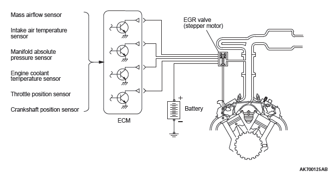
SYSTEM DIAGRAM
<2.4L Engine>
<3.0L Engine>
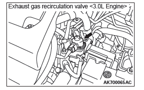
COMPONENT LOCATION
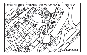
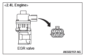
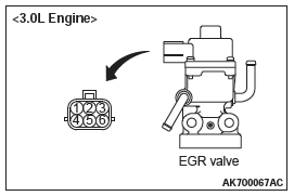
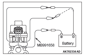
EGR VALVE (STEPPER MOTOR) CHECK
Required Special Tool: MB991658: Test Harness Set
Checking the Operation Sound
1. Check that the operation sound of the stepper motor can be heard from the EGR valve when the ignition switch is turned ON (without starting the engine).
2. If the operation sound cannot be heard, inspect the drive circuit of the stepper motor.
NOTE: If the operation sound is not heard, and the circuit is normal, either the stepper motor or the ECM may have failed.
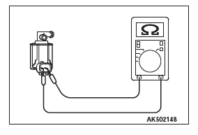
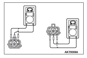
Checking the Coil Resistance
1. Remove the EGR valve.
2. Measure the resistance between terminal No. 2 and either terminal No. 1 or terminal No. 3 of the connector at the EGR valve.
Standard value: 20 − 24 Ω [at 20ºC (68ºF) ]
3. If the resistance is not within the standard, replace the EGR valve.
4. Measure the resistance between terminal No. 5 and either terminal No. 6 or terminal No. 4 of the connector at the EGR valve.
Standard value: 20 − 24 Ω [at 20ºC (68ºF) ]
5. If the resistance is not within the standard, replace the EGR valve.
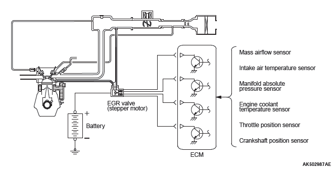
Operation Check
1. Remove the EGR valve.
2. Connect special tool MB991658 to the EGR valve.
3. Connect the battery positive (+) terminal to terminal No. 2.
CAUTION Connecting battery voltage to the EGR valve for a long time could damage the coil.
4. Connect terminals 1 and 3 to the negative (-) terminal of the battery, in order to test whether the stepper motor vibrates (with a slight shudder), indicating that the stepper motor is operating.
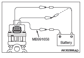
5. Connect the battery positive (+) terminal to terminal No. 5.
CAUTION Connecting battery voltage to the EGR valve for a long time could damage the coil.
6. Connect terminals 4 and 6 to the negative (-) terminal of the battery, in order to test whether the stepper motor vibrates (with a slight shudder), indicating that the stepper motor is operating.
7. If vibrations can be felt as a result of the test, the stepper motor is determined to be normal.
MASS AIRFLOW SENSOR CHECK
<2.4L Engine>
To inspect these parts, refer to GROUP 13A, Multiport Fuel Injection (MFI) <2.4L Engine> − Multiport Fuel Injection (MFI) Diagnosis − Diagnostic Trouble Code Chart.
<3.0L Engine>
To inspect these parts, refer to GROUP 13B, Multiport Fuel Injection (MFI) <3.0L Engine> − Multiport Fuel Injection (MFI) Diagnosis − Diagnostic Trouble Code Chart.
ENGINE COOLANT TEMPERATURE SENSOR CHECK
<2.4L Engine>
To inspect the sensor, refer to GROUP 13A, Multiport Fuel Injection (MFI) <2.4L Engine> − Multiport Fuel Injection (MFI) Diagnosis − Diagnostic Trouble Code Chart.
<3.0L Engine>
To inspect the sensor, refer to GROUP 13B, Multiport Fuel Injection (MFI) <3.0L Engine> − Multiport Fuel Injection (MFI) Diagnosis − Diagnostic Trouble Code Chart.
CRANKSHAFT POSITION SENSOR CHECK
<2.4L Engine>
To inspect the sensor, refer to GROUP 13A, Multiport Fuel Injection (MFI) <2.4L Engine> Multiport Fuel Injection (MFI) Diagnosis − Diagnostic Trouble Code Chart.
<3.0L Engine>
To inspect the sensor, refer to GROUP 13B, Multiport Fuel Injection (MFI) <3.0L Engine> − Multiport Fuel Injection (MFI) Diagnosis − Diagnostic Trouble Code Chart.
REMOVAL AND INSTALLATION <2.4L ENGINE>
Pre-removal Operation
- Engine Coolant Draining
- Air Cleaner Intake Hose and Air Cleaner Assembly Removal
- Oil Filler Tube Assembly Removal
Post-installation Operation
- Oil Filler Tube Assembly Installation
- Air Cleaner Intake Hose and Air Cleaner Assembly Installation
- Engine Coolant Refilling
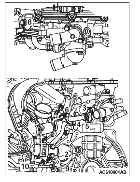
Removal steps
- EGR valve connector connection
- EGR valve
- EGR valve gasket
- EGR valve pipe
- EGR pipe gasket
- EGR pipe gasket
- Water hose connection
- EGR support stay A
- EGR support stay B
- Throttle body assembly
- EGR valve support
- EGR pipe gasket
- EGR inlet pipe
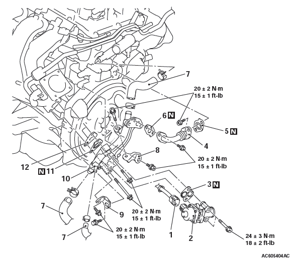
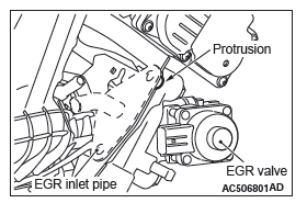
INSTALLATION SERVICE POINTS
EGR PIPE GASKET/EGR VALVE SUPPORT/ EGR SUPPORT STAY B/EGR SUPPORT STAY A/ EGR PIPE GASKET/EGR VALVE PIPE INSTALLATION
1. Temporarily tighten each part so that the protrusion of each gasket is positioned as illustrated
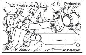
2. Tighten mounting bolts to the specified torque in the order of number shown in the figure.
Tightening torque: 20 +- 2 N*m (15 +- 1 ft-lb)
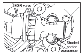
EGR VALVE GASKET INSTALLATION
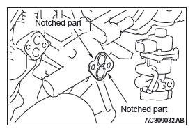
Install the EGR valve gasket so that its shaded portion is set as shown in the figure.
REMOVAL AND INSTALLATION <3.0L ENGINE>
Pre-removal Operation
- Engine Coolant Draining
- Air Cleaner Intake Hose and Air Cleaner Assembly Removal
Post-installation Operation
- Air Cleaner Intake Hose and Air Cleaner Assembly Installation - Engine Coolant Refilling
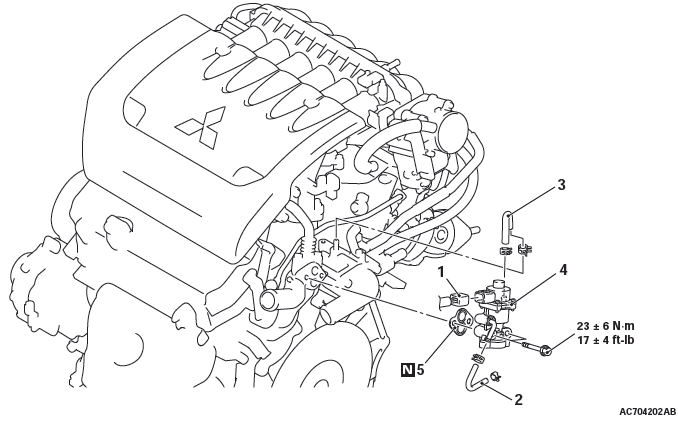
Removal steps
- EGR valve connector connection
- Water hose
- Water hose
- EGR valve
- EGR valve gasket
INSTALLATION SERVICE POINT
EGR VALVE GASKET INSTALLATION
Install the EGR valve gasket as shown in the illustration.
EVAPORATIVE EMISSION CANISTER AND FUEL TANK PRESSURE RELIEF VALVE
REMOVAL AND INSTALLATION
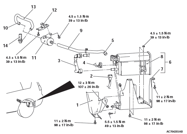
Removal steps
- Evaporative emission canister protector
- Evaporative emission ventilation solenoid connector connection
- Fuel vapor tube assembly
- Fuel purge pipe assembly connection
- Vent hose A connection
- Evaporative emission canister and bracket assembly
- Evaporative emission canister bracket
- Evaporative emission canister and evaporative emission ventilation solenoid assembly
- Vent hose A
- Vent hose B connection
- Air filter
- Air filter bracket
- Rear axle driveshaft (LH)
- Vent hose B
- Vent pipe
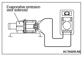
INSPECTION
EVAPORATIVE EMISSION VENTILATION SOLENOID CHECK
1. Connect a hand vacuum pump to nipple (A) of the evaporative emission canister and evaporative emission ventilation solenoid assembly.
2. Connect a plug to nipple (B) of the evaporative emission canister and evaporative emission ventilation solenoid assembly.
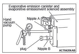
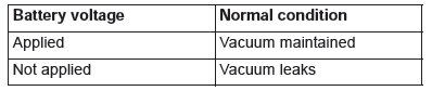
3. Check air tightness by applying a vacuum with voltage applied directly from the battery to the evaporative emission ventilation solenoid and without applying voltage.
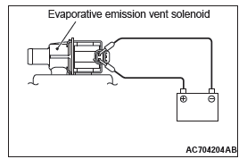
4. Measure the resistance between the terminals of the solenoid.
Standard value: 17 − 21 Ω [at 20ºC (68ºF) ]
CATALYTIC CONVERTER
REMOVAL AND INSTALLATION
- The catalytic converter is integrated with the center exhaust pipe. The removal and installation is the same as the center exhaust pipe <2.4L Engine>.
- The catalytic converter is integrated with the exhaust manifold and center exhaust pipe. The removal and installation is the same as the exhaust manifold and center exhaust pipe and <3.0L Engine>.
READ NEXT:
 Multiport Fuel Injection (MFI) - 2.4L Engine
General Information
The Multiport Fuel Injection System consists of sensors
which detect the engine conditions, the ENGINE
CONTROL MODULE (ECM) which controls the system
based on signals from these se
Troubleshooting Strategy, Diagnostic Function
TROUBLESHOOTING STRATEGY
NOTE: If a DTC is erased, its "freeze frame" data will
also be erased and system readiness test status will
be reset. Store the "freeze frame" data before erasing
the DTC.
Use
SEE MORE:
Steering Column Shaft
Assembly
REMOVAL AND INSTALLATION
CAUTION
Before removing the steering wheel/driver's air bag module assembly,
refer to GROUP 52B − Service
Precautions and Driver's Air Bag Module Clock Spring.
After the installation, perform a calibration for the ASC-ECU to
learn the steering wheel sensor
ne
Transaxle
DISASSEMBLY AND ASSEMBLY
CAUTION
Use a fluid of the designated brand for transmission fluid. Use of
transmission fluid not specified
by the manufacturer can affect driveability and the durability of the
automatic transmission, and
can even lead to damage to the transmission.
Perform disasse
