Mitsubishi Outlander: Troubleshooting Strategy, Diagnostic Function
TROUBLESHOOTING STRATEGY
NOTE: If a DTC is erased, its "freeze frame" data will also be erased and system readiness test status will be reset. Store the "freeze frame" data before erasing the DTC.
Use these steps to plan your diagnostic strategy. If you follow them carefully, you will be sure to have exhausted most of the possible ways to find an MFI fault.
1. Gather as much information as possible about the complaint from the customer.
2. Verify that the condition described by the customer exists.
3. Check the vehicle for any MFI Diagnostic Trouble Code (DTC).
4. If you cannot verify the condition and there are no DTCs, the malfunction is intermittent. For information on how to cope with intermittent malfunctions, refer to GROUP 00, How to Use Troubleshooting/Inspection Service Points − How to Cope with Intermittent Malfunctions.
5. If you can verify the condition but there are no DTCs, or the system cannot communicate with the scan tool, refer to the trouble symptom classification table.
6. If there is a DTC, store the number of the code, then erase the code from the memory using the scan tool.
7. Reconfirm the malfunction symptom and carry out a test drive with the drive cycle pattern.
8. If DTC is set again, carry out an inspection with appropriate diagnostic trouble code procedures.
9. If DTC is not set again, the malfunction is intermittent. For information on how to cope with intermittent malfunctions, refer to GROUP 00, How to Use Troubleshooting/Inspection Service Points − How to Cope with Intermittent Malfunctions.
10.After repairs are completed, conduct a road test duplicating the complaint set conditions to confirm the malfunction has been corrected.
11.Erase the permanent DTC. (Refer to DIAGNOSTIC FUNCTION − PERMANENT DTC for the procedures of erasing the permanent DTC)
NOTE: This is carried out to prevent the failure to pass the Inspection and Maintenance (I/M) test in the states checking whether the permanent DTC is stored or not.
NOTE: If the engine control module (ECM) is replaced, Immobilizer Encrypted Code Registration should be carried out, refer to GROUP 42B, Diagnosis − ID Code Registration Judgment Table <Vehicles with KOS> or GROUP 42C, Diagnosis − ID Codes Registration Judgment Table <Vehicles with WCM>.
DIAGNOSTIC FUNCTION
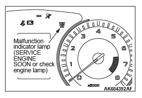
MALFUNCTION INDICATOR LAMP (SERVICE ENGINE SOON OR CHECK ENGINE LAMP)
Among the on-board diagnostic items, Malfunction Indicator Lamp (SERVICE ENGINE SOON or Check Engine Lamp) illuminates to notify the driver of an emission control malfunction.
However, when an irregular signal returns to normal and the engine control module judges that it has returned to normal, the Malfunction Indicator Lamp (SERVICE ENGINE SOON or Check Engine Lamp) will switch off.
There are two methods for checking the indicator lamp burn out: When the ignition switch is in ON position, the indicator lamp is illuminated, and then extinguished few seconds later.
When the ignition switch is in ON position and the engine starts, the indicator lamp is extinguished.
NOTE: When the Transaxle Control Module (TCM) detects malfunctions related to the CVT, the Malfunction indicator Lamp (SERVICE ENGINE SOON or Check Engine Lamp) is also illuminated.
Items Indicated by the Malfunction Indicator Lamp (SERVICE ENGINE SOON or Check Engine Lamp)
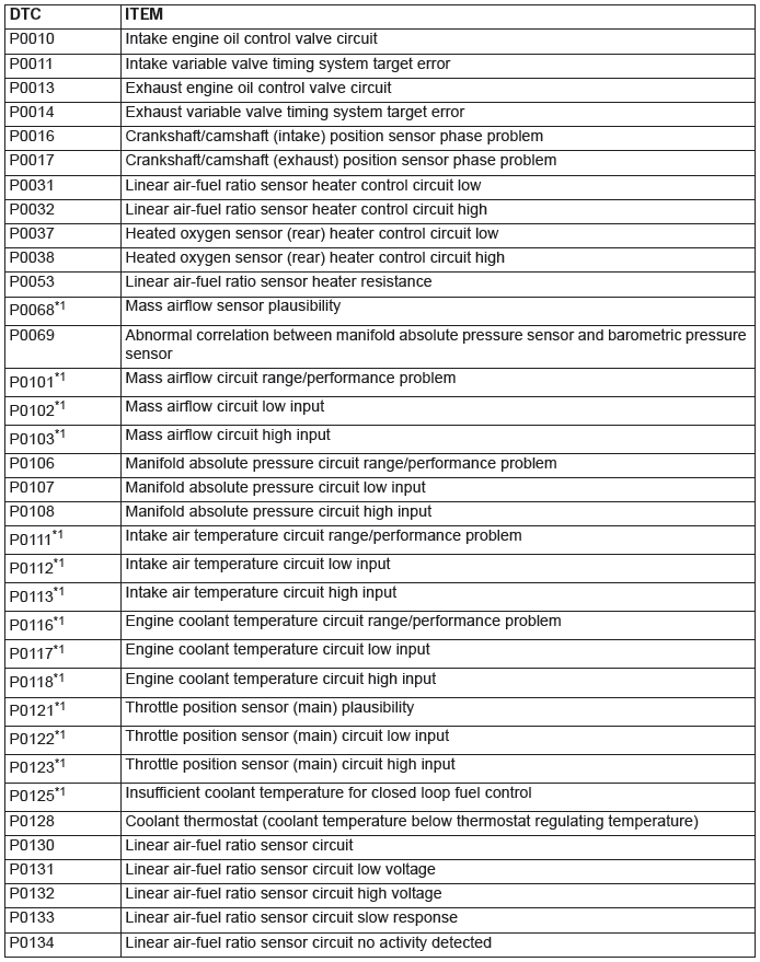

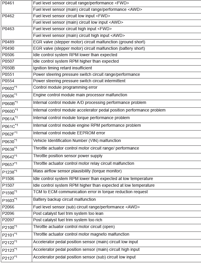
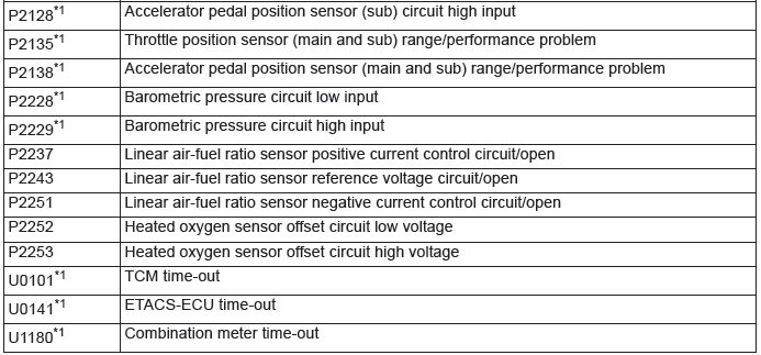
NOTE: After the ECM has detected a malfunction, the Malfunction Indicator Lamp (SERVICE ENGINE SOON or Check Engine Lamp) illuminates when the engine is next turned on and the same malfunction is re-detected. However, for items marked with a "*1" in the DTC NO. column, the Malfunction Indicator Lamp (SERVICE ENGINE SOON or Check Engine Lamp) illuminates only on the first detection of the malfunction.
NOTE: The codes marked with a "*2" in the diagnosis code number column have the following two conditions for illuminating the Malfunction Indicator Lamp (SERVICE ENGINE SOON or Check Engine Lamp).
- In case that the misfire causing the damaged catalyst is detected, the Malfunction Indicator Lamp (SERVICE ENGINE SOON or Check Engine Lamp) is illuminated at the time.
- In case that the misfire deteriorating the exhaust gas is detected, the Malfunction Indicator Lamp (SERVICE ENGINE SOON or Check Engine Lamp) is illuminated when the same malfunction is redetected after the next engine start.
NOTE: After the Malfunction Indicator Lamp (SERVICE ENGINE SOON or Check Engine Lamp) illuminates, it will be switched off under the following conditions.
- When the ECM monitored the powertrain malfunction three times* and met set condition requirements, it detected no malfunction. *: In this case, "one time" indicates from engine start to next engine start.
- For misfiring or a fuel trim malfunction, when driving conditions (engine speed, engine coolant temperature, etc.) are similar to those when the malfunction was first recorded.
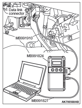
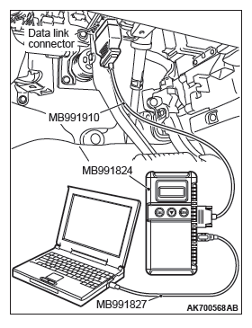
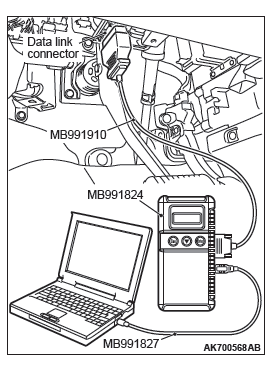
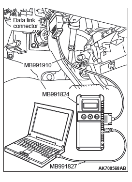
HOW TO CONNECT THE SCAN TOOL (M.U.T.-III)
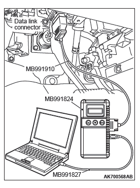
Required Special Tools:
- MB991958: Scan Tool (M.U.T.-III Sub Assembly)
- MB991824: V.C.I.
- MB991827: USB Cable
- MB991910: Main Harness A
CAUTION
To prevent damage to scan tool MB991958, always turn the ignition switch to the "LOCK" (OFF) position before connecting or disconnecting scan tool MB991958.
1. Ensure that the ignition switch is at the "LOCK" (OFF) position.
2. Start up the personal computer.
3. Connect special tool MB991827 to special tool MB991824 and the personal computer.
4. Connect special tool MB991910 to special tool MB991824.
5. Connect special tool MB991910 to the data link connector.
6. Turn the power switch of special tool MB991824 to the "ON" position.
NOTE: When the special tool MB991824 is energized, special tool MB991824 indicator light will be illuminated in a green color.
7. Start the M.U.T.-III system on the personal computer.
NOTE: Disconnecting the scan tool MB991958 is the reverse of the connecting sequence, making sure that the ignition switch is at the "LOCK" (OFF) position.
HOW TO READ AND ERASE DIAGNOSTIC TROUBLE CODES.
Required Special Tools:
- MB991958: Scan Tool (M.U.T.-III Sub Assembly)
- MB991824: V.C.I.
- MB991827: USB Cable
- MB991910: Main Harness A
CAUTION To prevent damage to scan tool MB991958, always turn the ignition switch to the "LOCK" (OFF) position before connecting or disconnecting scan tool MB991958.
1. Connect scan tool MB991958 to the data link connector.
2. Turn the ignition switch to the "ON" position.
3. Select "System select".
4. Choose "from 2006 MY" under "MODEL YEAR".
5. Check that "Vehicle Information" contents are correct.
6. Choose "MFI".
7. Select "Diagnostic Trouble Code"
8. If a DTC is set, it is shown.
9. Choose "Erase DTCs" to erase the DTC.
HOW TO READ DATA LIST
Required Special Tools:
- MB991958: Scan Tool (M.U.T.-III Sub Assembly)
- MB991824: V.C.I.
- MB991827: USB Cable
- MB991910: Main Harness A
CAUTION To prevent damage to scan tool MB991958, always turn the ignition switch to the "LOCK" (OFF) position before connecting or disconnecting scan tool MB991958.
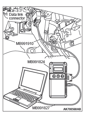
1. Connect scan tool MB991958 to the data link connector.
2. Turn the ignition switch to the "ON" position.
3. Select "System select".
4. Choose "from 2006 MY" under "MODEL YEAR".
5. Check that "Vehicle Information" contents are correct.
6. Choose "MFI".
7. Select "Data List".
8. Choose an appropriate item and select the "OK" button.
HOW TO PERFORM ACTUATOR TEST
Required Special Tools:
- MB991958: Scan Tool (M.U.T.-III Sub Assembly)
- MB991824: V.C.I.
- MB991827: USB Cable
- MB991910: Main Harness A
CAUTION To prevent damage to scan tool MB991958, always turn the ignition switch to the "LOCK" (OFF) position before connecting or disconnecting scan tool MB991958.
1. Connect scan tool MB991958 to the data link connector.
2. Turn the ignition switch to the "ON" position.
3. Select "System select".
4. Choose "from 2006 MY" under "MODEL YEAR".
5. Check that "Vehicle Information" contents are correct.
6. Choose "MFI".
7. Select "Actuator Test".
8. Choose an appropriate item and select the "OK" button.
HOW TO DIAGNOSE THE CAN BUS LINES
Required Special Tools:
- MB991958: Scan Tool (M.U.T.-III Sub Assembly)
- MB991824: V.C.I.
- MB991827: USB Cable
- MB991910: Main Harness A
CAUTION To prevent damage to scan tool MB991958, always turn the ignition switch to the "LOCK" (OFF) position before connecting or disconnecting scan tool MB991958.
1. Connect scan tool MB991958 to the data link connector.
2. Turn the ignition switch to the "ON" position.
3. Select "CAN bus diagnosis" from the start-up screen.
4. When the vehicle information is displayed, confirm that it matches the vehicle whose CAN bus lines will be diagnosed.
- If they matches, go to step 8.
- If not, go to step 5.
5. Select the "view vehicle information" button.
6. Enter the vehicle information and select the "OK" button.
7. When the vehicle information is displayed, confirm again that it matches the vehicle whose CAN bus lines will be diagnosed.
- If they matches, go to step 8.
- If not, go to step 5.
8. Select the "OK" button.
9. When the optional equipment screen is displayed, choose the one which the vehicle is fitted with, and then select the "OK" button.
HOW TO READ PROVISIONAL DIAGNOSTIC TROUBLE CODES
Required Special Tools:
- MB991958: Scan Tool (M.U.T.-III Sub Assembly)
- MB991824: V.C.I.
- MB991827: USB Cable
- MB991910: Main Harness A
If detecting the malfunction during the first drive cycle, the ECM temporarily stores the diagnosis code as the provisional diagnosis code. If detecting the same malfunction during the next drive cycle, the ECM determines that the malfunction exists.
The ECM outputs the diagnosis code. On Scan Tool MB991958, it is possible to display the stored provisional diagnosis code which the ECM had detected during the first drive cycle. This makes it possible to confirm in one drive cycle whether the malfunction could happen again after the repair.
CONFIRMATION METHOD
CAUTION To prevent damage to scan tool MB991958, always turn the ignition switch to the "LOCK" (OFF) position before connecting or disconnecting scan tool MB991958.
1. Connect scan tool MB991958 to the data link connector.
2. Turn the ignition switch to the "ON" position.
3. Select "System select".
4. Choose "from 2006 MY" under "MODEL YEAR".
5. Check that "Vehicle Information" contents are correct.
6. Choose "MFI".
7. Select "Special Function" from MFI Screen.
8. Select "Provisional DTCs" from Special Function Screen.
PERMANENT DTC
The permanent DTC(PDTC) is stored in the EEPROM of the engine control module (ECM) as the permanent status, which checks that the malfunction of the emission related components/ the system has not been repaired yet. When detecting the malfunction necessary to illuminate the malfunction indicator lamp (SERVICE ENGINE SOON or Check Engine Lamp), the ECM illuminates the MIL and stores the appropriate DTC as the permanent DTC in the EEPROM concurrently. The usual DTC is stored in the EEPROM aside from this. The ECM can store up to 6 PDTCs. The ECM, therefore, cannot store the 7th and subsequent PDTCs. If the temporary malfunction causes the malfunction indicator lamp to be illuminated and then the reinstatement during the subsequent driving causes it to be extinguished, the PDTC is erased. Also if the ECM checks that the DTC malfunction is fixed during the driving after the DTC repair is completed, the PDTC is erased. The permanent DTC, however, is not erased by disconnecting the battery terminal or erasing with the scan tool (M.U.T-III). The permanent DTC can be erased if all readiness statuses are erased or not completed at the time of reprogramming the ECM. If must be erased while the vehicle is repaired, the PDTC can be erased by the procedures shown below. If must be erased because of the failure to pass the Inspection and Maintenance (I/M) test, the permanent DTC can also be erased by the following procedure:
PROCEDURES FOR ERASING PERMANENT DTC
1. Check that the DTC is not stored. If the DTC is stored, perform the DTC troubleshooting, then repair the DTC.
NOTE: The order of step 2 and 3 can be exchanged.
2. Drive the vehicle at least once under the conditions satisfying all the following requirements:
- The total driving (engine running) time must be more than 10 consecutive minutes.
- More than 30 seconds of idling must be included in the driving
- More than 5 consecutive minutes of driving at more than 40 km/h (25 mph) must be included in the driving.
3. Drive the vehicle at least two times in the drive cycle pattern suitable for the permanent DTC. (Refer to OBD-II DRIVE CYCLE for the drive cycle pattern.) If the DTC does not have the drive cycle pattern, start and stop the engine. Wait 15 seconds or more to start again after the stop. Repeat at least 2 times.
4. Restart and stop the engine.
5. Check that the permanent DTC is erased. If the permanent DTC is not erased, check the DTC or the provisional DTC. If the malfunction code is stored, repair the DTC. Try to erase the permanent DTC again (from Step 1 to 5). If the malfunction code is not stored, the drive cycle pattern (Step 3) monitoring the malfunction can possibly be insufficient.
MODE 6 REFERENCE TABLE
The engine control module (ECM) monitors the condition of emission control system.
By selecting MODE 6 using scan tool, Test Result and Limit Value (minimum) *1 or (maximum) *2 about the main items of emission control system which ECM monitors can be confirmed. The value at the last monitoring is output by ECM as a test result.
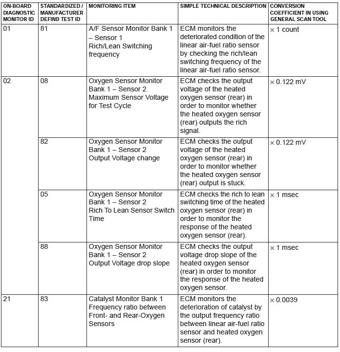
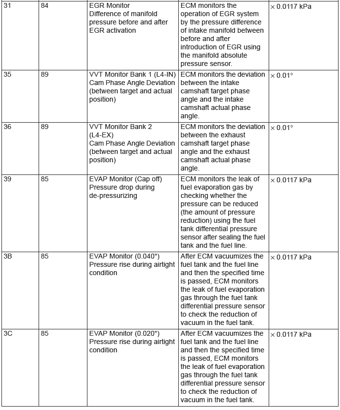
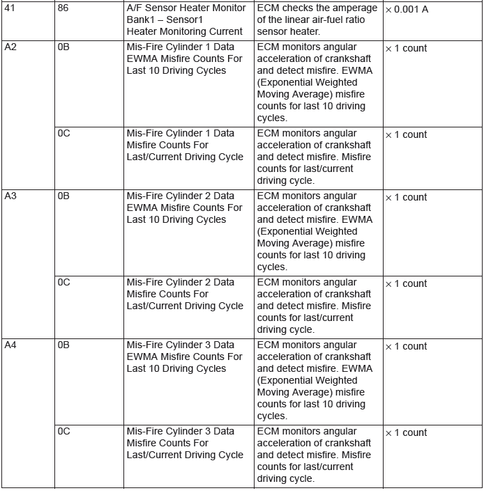

NOTE: *1: Minimum value: The test fails if test value is less than this value.
NOTE: *2: Maximum value: The test fails if test value is greater than this value.
NOTE: When not finishing the monitor of the driving cycle for the request of On-Board Monitoring Test Request, the ECM outputs the stored latest monitor test result.
NOTE: When the monitored test results are erased by the battery disconnection and so on, the ECM outputs the values in hexadecimal of "0000" or "FFFF", otherwise it outputs abnormal values and so on. In case of this, the ECU outputs are handled as invalid-values. When the first monitor (Readiness Status) is completed after this, the ECM outputs the valid-values.
NOTE: "Test Limit Type & Component ID byte" output from the ECM is given in hexadecimal of "00" or "80".
"00" means the maximum value and "80" means the minimum value.
ON-BOARD DIAGNOSTICS
The engine control module (ECM) monitors the input/output signals (some signals all the time and others under specified conditions) of the ECM. When a malfunction continues for a specified time or longer after the irregular signal is initially monitored, the ECM judges that a malfunction has occurred. After the ECM first detects a malfunction, a diagnostic trouble code is recorded when the engine is restarted and the same malfunction is re-detected. However, for items marked with a "*1", a diagnostic trouble code is recorded on the first detection of the malfunction.
There are 138 diagnostic items. The diagnostic results can be read out with a scan tool. Since memorization of the diagnostic trouble codes is backed up directly by the battery, the diagnostic results are memorized even if the ignition key is turned off. The diagnostic trouble codes will, however, be erased when the battery terminal or the ECM connector is disconnected. In addition, the diagnostic trouble code can also be erased by turning the ignition switch to ON and sending the diagnostic trouble code erase signal from scan tool MB991958 to the ECM.
NOTE: If the sensor connector is disconnected with the ignition switch turned on, the diagnostic trouble code is memorized. In this case, send the diagnostic trouble code erase signal to the ECM in order to erase the diagnostic memory. The 138 diagnostic items are all indicated sequentially from the smallest code number. The ECM records the engine operating condition when the diagnostic trouble code is set.
This data is called "Freeze-frame" data. This data can be read by using the scan tool, and can then be used in simulation tests for troubleshooting. Data items are as follows: NOTE: If the ECM detects multiple malfunctions, the ECM stores the "Freeze-frame" data for only the first item that was detected. However, if the ECM detects a misfire or a fuel system malfunction, the ECM stores the data by giving priority to the misfire or fuel system malfunction, regardless of the order in which the malfunction was detected.
NOTE: As for Diagnostic trouble code P1603, "Freeze-frame" data is not memorized.
Freeze Frame Data for M.U.T.-III

NOTE: *: Accumulated time of current malfunction from time point when malfunction is detected.
Freeze Frame Data (OBD) for M.U.T.-III
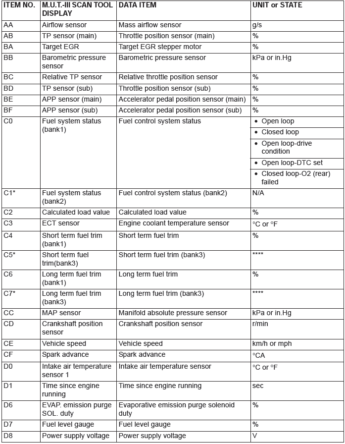

NOTE: *: Data items are displayed on M.U.T.-III display, but the in-line 4 engine is not applicable and its data is displayed as "N/A" or "****".
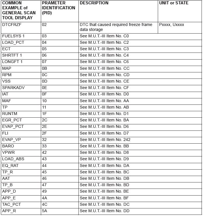
Freeze Frame Data for General Scan Tool
OBD- II DRIVE CYCLE
All kinds of diagnostic trouble codes (DTCs) can be monitored by carrying out a short drive according to the following 23 drive cycle patterns. In other words, doing such a drive regenerates any kind of trouble which involves illuminating the Malfunction Indicator Lamp (SERVICE ENGINE SOON or Check Engine Lamp) and verifies the repair procedure has been eliminated [the trouble the Malfunction Indicator Lamp (SERVICE ENGINE SOON or Check Engine Lamp) is no longer illuminated].
CAUTION
Two technicians should always be in the vehicle when carrying out a test.
NOTE: Check that the diagnosis trouble code (DTC) is not output before driving the OBD-II drive cycle. Erase the DTC if it has been output.
NOTE: Drive cycle patterns are not established for Power steering pressure switch monitor (P0551), and Fuel level sensor monitor (DTC P0461, P2066 <AWD>). Please reference the M.U.T. data list to judge whether these monitor items are normal.
DRIVE CYCLE PATTERN LIST
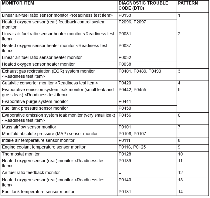
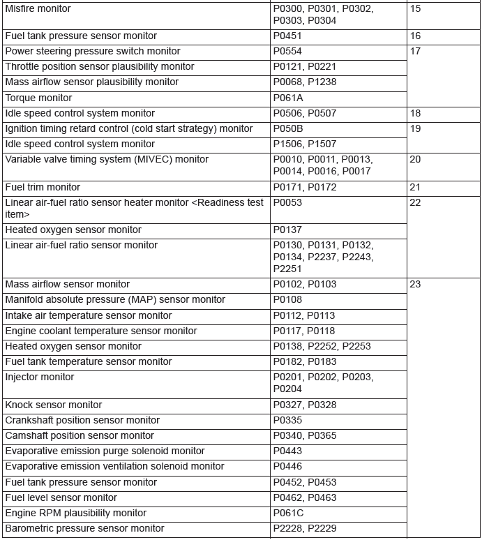
PATTERN 1
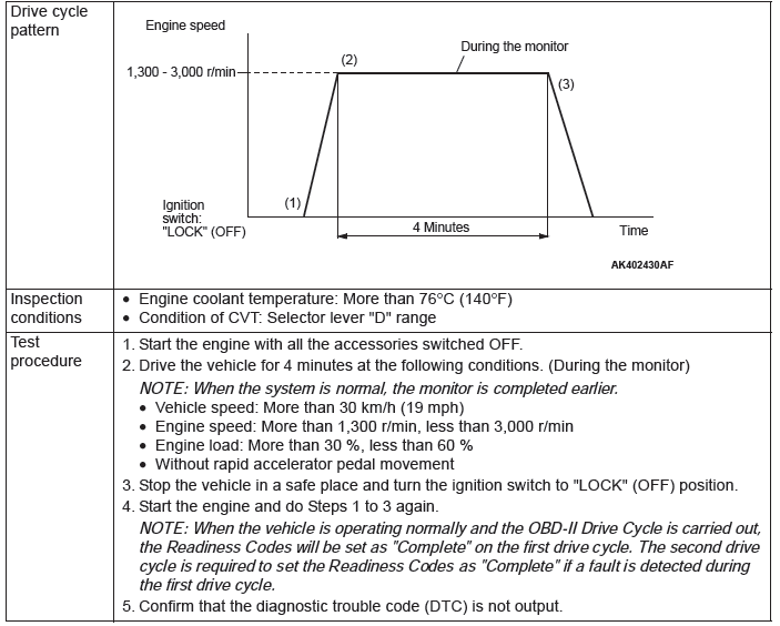
PATTERN 2

PATTERN 3
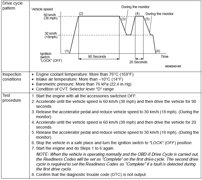
PATTERN 4
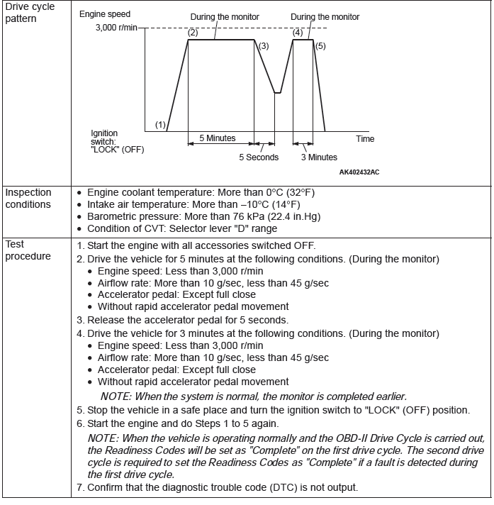
PATTERN 5
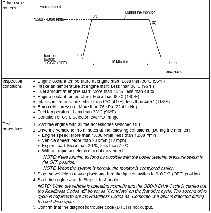
PATTERN 6
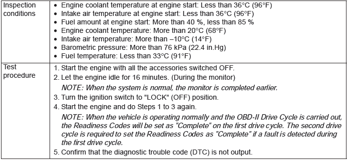
PATTERN 7
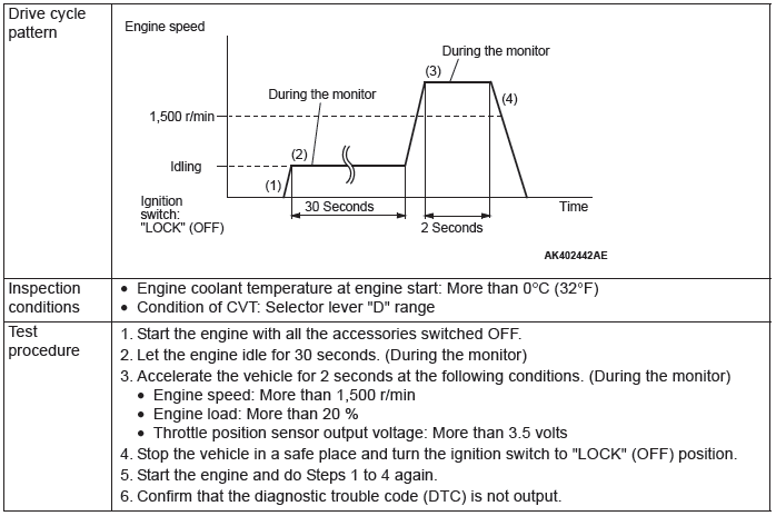
PATTERN 8
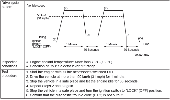
PATTERN 9
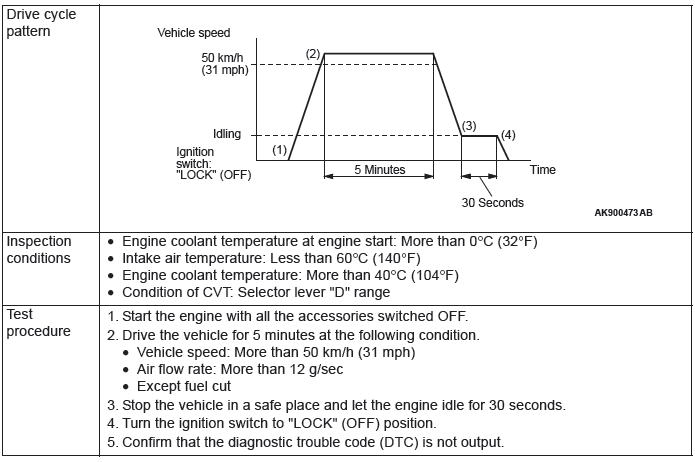
PATTERN 10
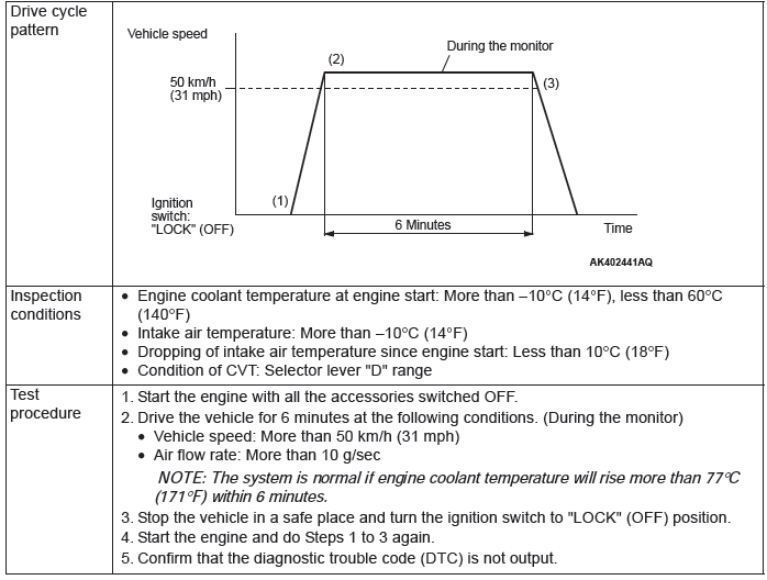
PATTERN 11
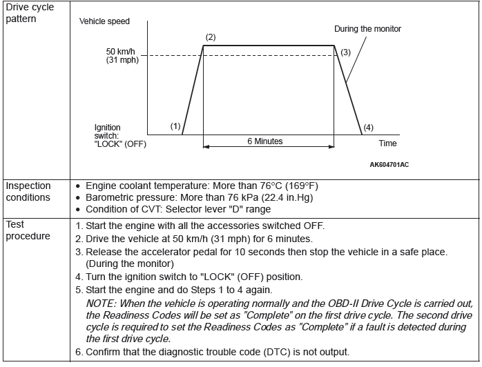
PATTERN 12
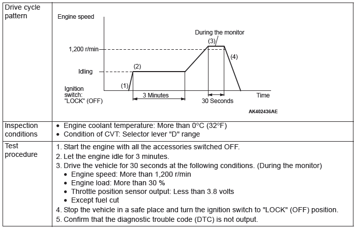
PATTERN 13
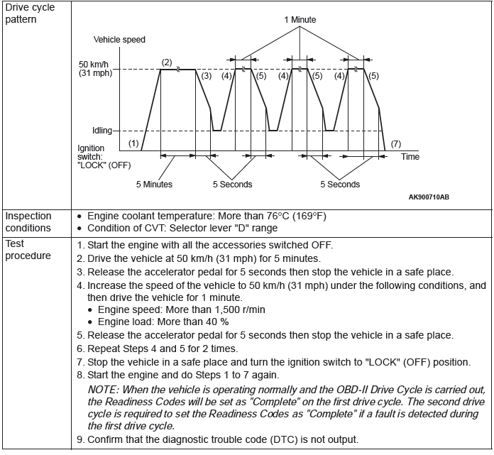
PATTERN 14

PATTERN 15
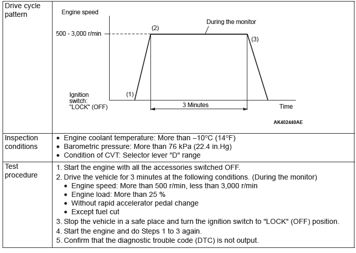
PATTERN 16
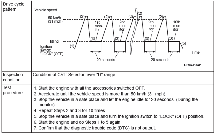
PATTERN 17
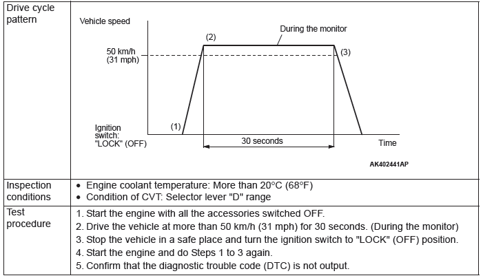
PATTERN 18

PATTERN 19

PATTERN 20

PATTERN 21

PATTERN 22

PATTERN 23

SYSTEM READINESS TEST STATUS
PURPOSE
The Readiness function (also referred to as I/M Readiness or I/M Flags) indicates if a full diagnostic check has been "Completed" (is "Ready") for each non-continuous monitor. Enhanced I/M State Emission Programs will use the Readiness status (Codes) to see if the vehicle is ready for OBD-II testing.
"Incomplete" (Not Ready) codes will be one of the triggers for I/M failure.
OVERVIEW
The ECM monitors the following main diagnosis items and records whether the evaluation was completed or is incomplete. The Readiness Codes are established for the I/M programs, thereby confirming that the vehicles have not been tampered with by erasing the diagnostic trouble code(s) (DTCs) before I/M testing. The Readiness Codes and DTCs can be reset by disconnecting the battery or by erasing the codes with a scan tool MB991958 (M.U.T.-III sub assembly). For this reason, all the Readiness Codes must be displayed "Complete" before I/M testing.
When the monitors run and complete, the scan tool MB991958 (M.U.T.-III sub assembly) will display the Readiness Codes as "Complete" (General Scan Tools display as "Ready"). When the vehicle is operating normally and the OBD-II Drive Cycle is carried out, the Readiness Codes will be set as "Complete" on the first drive cycle. For DTCs requiring two drive cycles to detect a fault, the second drive cycle is required to set the Readiness Codes as "Complete" if a fault is detected during the first drive cycle. If the fault is still there after the second drive cycle, a DTC will be set.
- Catalyst: P0420
- Evaporative system: P0442, P0455, P0456
- Linear air-fuel ratio sensor: P0133
- Linear air-fuel ratio sensor heater: P0031, P0053
- Heated oxygen sensor: P0139, P0140
- Heated oxygen sensor heater: P0037
- EGR system: P0401
After all the Readiness Codes are displayed as "Complete", the technician is assured that any DTCs related to the monitor will be displayed if the system has a problem. That is why some State's I/M programs require the Readiness Code as "Complete" before they check for DTCs.
NOTE: After a repair is made for a DTC, the technician should drive the OBD-II Drive Cycle checking that the scan tool MB991958 (M.U.T.-III Sub Assembly) displays all the Readiness Codes as "Complete".
FAIL-SAFE FUNCTION REFERENCE TABLE
When the main sensor malfunctions are detected by the diagnostic test mode, the vehicle is controlled by means of the following defaults.
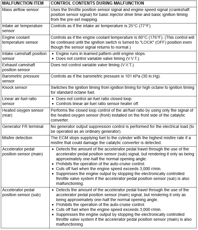
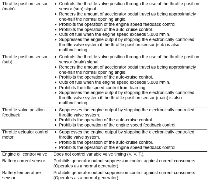
DIAGNOSTIC TROUBLE CODE CHART
WARNING
When touching the throttle valve, surely shut off the driving circuits of the throttle valve. In the event that the throttle valve is operated, a finger might be injured as the result of being caught by the throttle valve.
CAUTION
During diagnosis, a DTC code associated with other system may be set when the ignition switch is turned on with connector(s) disconnected. On completion, confirm all systems for DTC(s). If DTC(s) are set, erase them all.
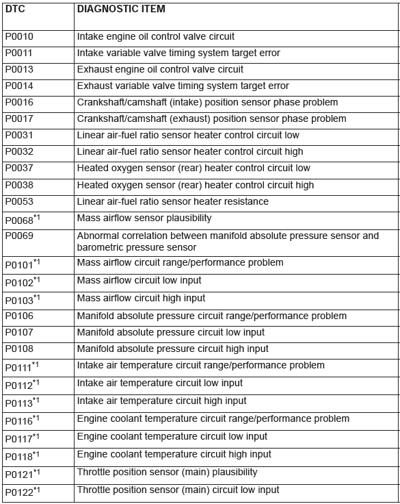
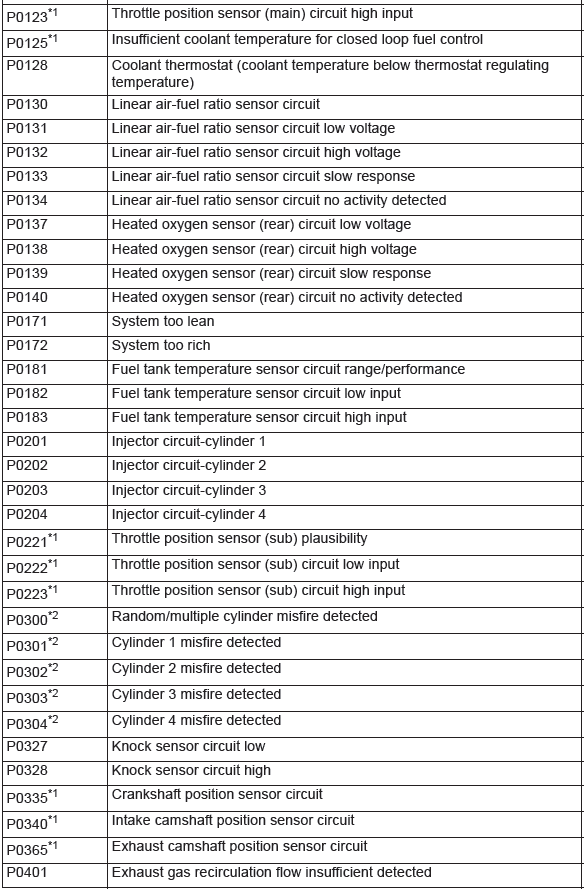
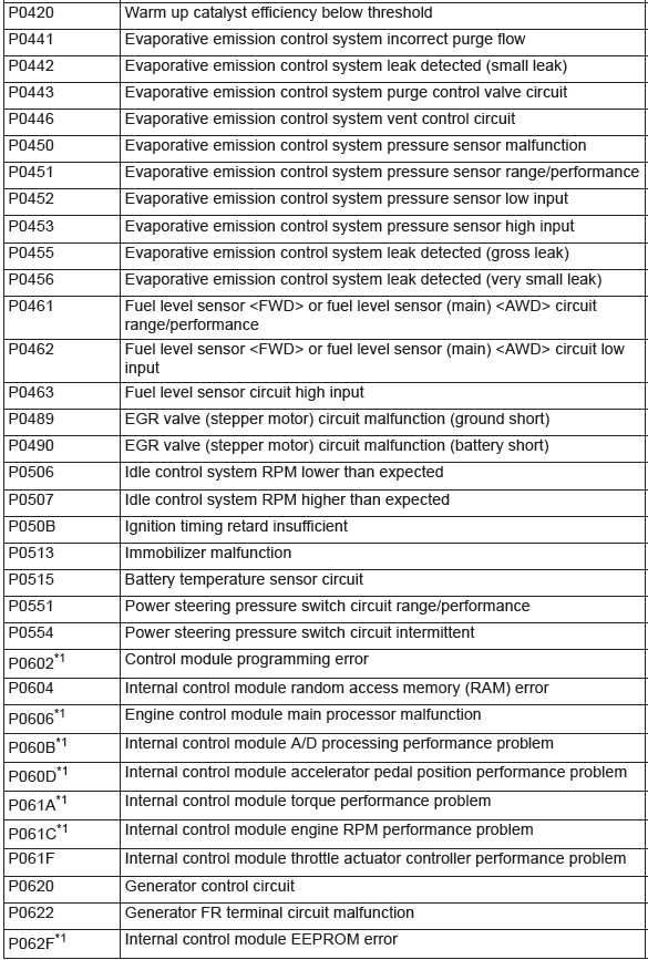
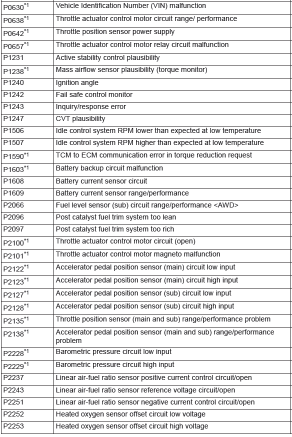
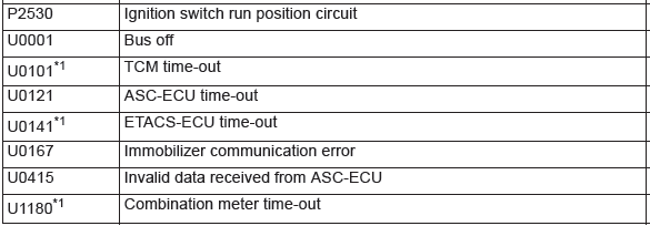
NOTE: Do not replace the engine control module (ECM) until a through terminal check reveals there are no short/open circuits.
NOTE: Check that the ECM ground circuit is normal before checking for the cause of the problem.
NOTE: After the ECM detects a malfunction, a diagnostic trouble code is recorded the next time the engine is started and the same malfunction is re-detected. However, for items marked with a "*1", the diagnostic trouble code is recorded on the first detection of the malfunction.
NOTE: The codes marked with a "*2" in the diagnosis code number column have the following two conditions for recording the diagnostic trouble code.
- In case that the misfire causing the damaged catalyst is detected, the diagnostic trouble code is recorded at the time.
- In case that the misfire deteriorating the exhaust gas is detected, the diagnostic trouble code is recorded when the same malfunction is redetected after the next engine start.
SYMPTOM CHART
WARNING
When touching the throttle valve, surely shut off the driving circuits of the throttle valve. In the event that the throttle valve is operated, a finger might be injured as the result of being caught by the throttle valve.
CAUTION
During diagnosis, a DTC associated with other systems may be set when the ignition switch is turned on with connector(s) disconnected. On completion, confirm all systems for DTC(s). If DTC(s) are set, erase them all.
CAUTION
Disconnecting the battery cables or removing the combination meter will erase the learned value of the fuel gauge. To recover the learned value, input a vehicle speed (by actually driving the vehicle or inputting a simulated vehicle speed), and stop the vehicle. This will complete the learning process.
NOTE: Check that the ECM ground circuit is normal before checking for the cause of the problem.
NOTE: When the racing (2,000 to 5,000 r/min or more) continues on the vehicle stopped with no load during the specified time or more, the increase in the engine speed might be limited. This comes from the engine protection and control functions and is not a malfunction.
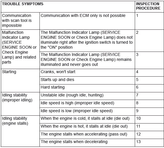
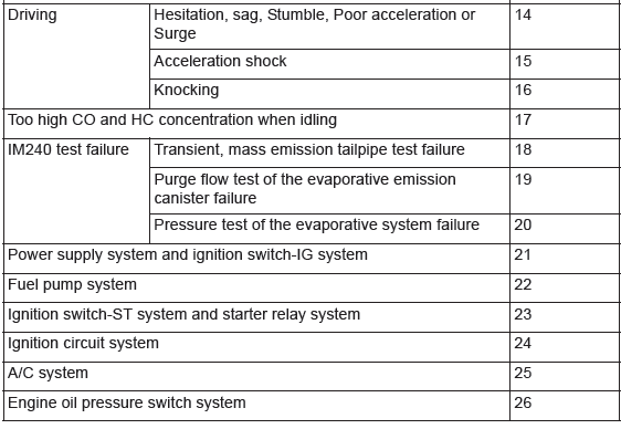
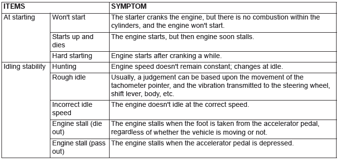
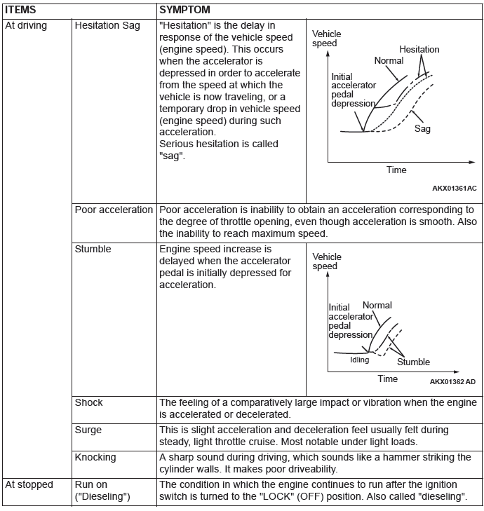
PROBLEM SYMPTOMS TABLE (FOR YOUR INFORMATION)
