Mitsubishi Outlander: DTC P0010, P0011, P0013, P0014, P0016, P0017, P0031, P0032, P0037, P0038
DTC P0010: Intake Engine Oil Control Valve Circuit
CIRCUIT OPERATION
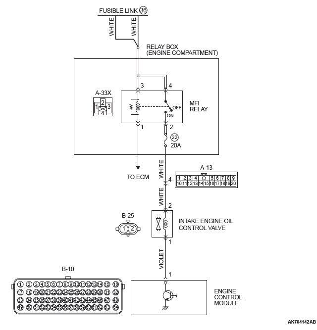
- The intake engine oil control valve power is supplied from the MFI relay (terminal No. 2).
- The ECM controls ground intake engine oil control valve by turning the power transistor in the ECM "ON" and "OFF".
TECHNICAL DESCRIPTION
- The intake engine oil control valve changes the phase angle to operate the MIVEC system in the advance or the retard side in accordance with signals from the ECM.
DESCRIPTIONS OF MONITOR METHODS
- Intake engine oil control valve circuit current is out of the specified range.
MONITOR EXECUTION
Continuous
MONITOR EXECUTION CONDITIONS (Other monitor and Sensor)
Other Monitor (There is no temporary DTC stored in memory for the item monitored below)
- Not applicable
Sensor (The sensor below is determined to be normal)
- Camshaft position sensor
- Crankshaft position sensor
- Engine coolant temperature sensor
- Throttle position sensor
- Engine oil control valve
DTC SET CONDITIONS
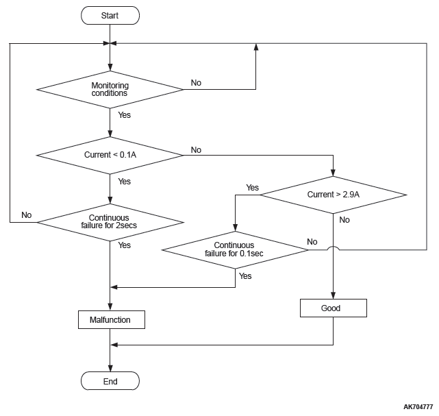
Logic Flow Chart

Check Conditions
- Ignition switch is "ON" position
- Battery positive voltage is between 10 and 16.5 volts.
- ON duty cycle of the intake engine oil control valve circuit is higher than 20 percent.
Judgement Criterion
- The ECM terminal current of intake engine oil control valve circuit is less than 0.1 ampere for 2 seconds.
Check Conditions
- Ignition switch is "ON" position
- Battery positive voltage is between 10 and 16.5 volts.
Judgement Criterion
- The ECM terminal current of intake engine oil control valve circuit is higher than 2.9 amperes for 0.1 second.
OBD-II DRIVE CYCLE PATTERN
- Refer to Diagnostic Function − OBD-II Drive Cycle − Pattern 20.
TROUBLESHOOTING HINTS (The most likely causes for this code to be set are:)
- Intake engine oil control valve failed.
- Open or shorted intake engine oil control valve circuit, harness damage, or connector damage.
- ECM failed.
DIAGNOSIS
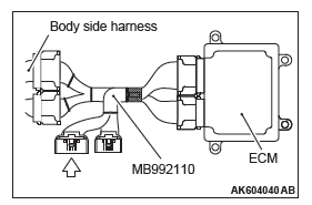
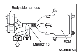
Required Special Tools:
- MB992110: Power Plant ECU Check Harness
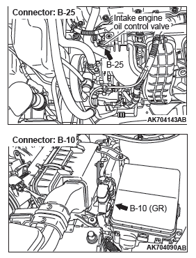
STEP 1. Check harness connector B-25 at the intake engine oil control valve for damage.
Q: Is the harness connector in good condition?
YES : Go to Step 2.
NO : Repair or replace it. Refer to GROUP 00E, Harness Connector Inspection. Then go to Step 10.
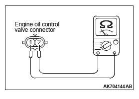
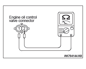
STEP 2. Check the intake engine oil control valve.
- Disconnect the intake engine oil control valve connector B-25.
- Measure the resistance between intake engine oil control valve side connector terminal No. 1 and No. 2.
Standard value: 6.9 − 7.9 ohms [at 20ºC (68ºF) ]
Q: Is the measured resistance between 6.9 and 7.9 ohms [at 20ºC (68ºF) ]?
YES : Go to Step 3.
NO : Replace the intake engine oil control valve. Then go to Step 10.
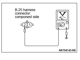
STEP 3. Measure the power supply voltage at intake engine oil control valve harness side connector B-25.
- Disconnect the connector B-25 and measure at the harness side.
- Turn the ignition switch to the "ON" position.
- Measure the voltage between terminal No. 2 and ground.
- Voltage should be battery positive voltage.
- Turn the ignition switch to the "LOCK" (OFF) position.
Q: Is battery positive voltage (approximately 12 volts) present?
YES : Go to Step 5.
NO : Go to Step 4.
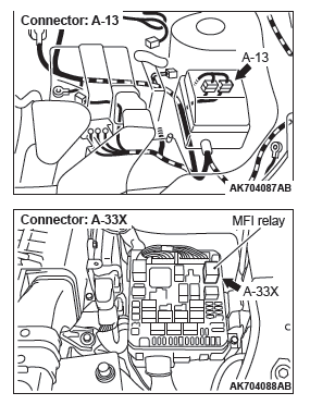
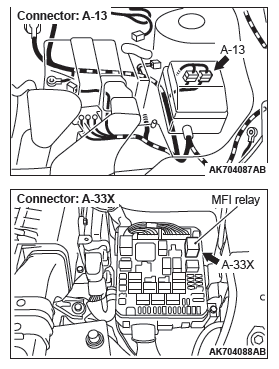
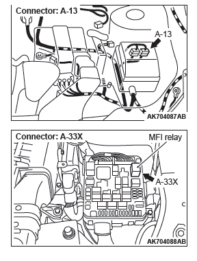
STEP 4. Check harness connector A-33X at MFI relay for damage.
Q: Is the harness connector in good condition?
YES : Check harness connector A-13 at intermediate connector for damage, and repair or replace as required. Refer to GROUP 00E, Harness Connector Inspection. If intermediate connector is in good condition, repair harness wire between MFI relay connector A-33X (terminal No. 2) and intake engine oil control valve connector B-25 (terminal No.2) because of open circuit or short circuit to ground.
Then go to Step 10.
NO : Repair or replace it. Refer to GROUP 00E, Harness Connector Inspection. Then go to Step 10.
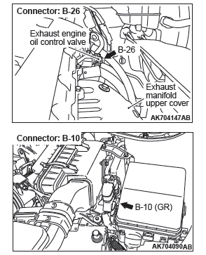
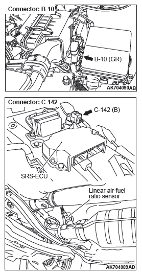
STEP 5. Check harness connector B-10 at ECM for damage.
Q: Is the harness connector in good condition?
YES : Go to Step 6.
NO : Repair or replace it. Refer to GROUP 00E, Harness Connector Inspection. Then go to Step 10.
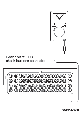
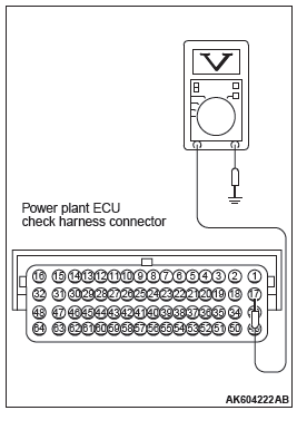
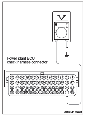
STEP 6. Measure the power supply voltage at ECM connector B-10 by using power plant ECU check harness special tool MB992110.
- Disconnect all ECM connectors. Connect the power plant ECU check harness special tool MB992110 between the separated connectors.
- Turn the ignition switch to the "ON" position.
- Measure the voltage between terminal No. 1 and ground.
- Voltage should be battery positive voltage.
- Turn the ignition switch to the "LOCK" (OFF) position.
Q: Is battery positive voltage (approximately 12 volts) present?
YES : Go to Step 7.
NO : Repair harness wire between intake engine oil control valve connector B-25 (terminal No. 1) and ECM connector B-10 (terminal No. 1) because of open circuit or short circuit to ground. Then go to Step 10.
STEP 7. Check for harness damage between MFI relay connector A-33X (terminal No. 2) and intake engine oil control valve connector B-25 (terminal No. 2).
NOTE: Check harness after checking intermediate connector A-13. If intermediate connector is damaged, repair or replace it.
Refer to GROUP 00E, Harness Connector Inspection.
Then go to Step 10.
Q: Is the harness wire in good condition?
YES : Go to Step 8.
NO : Repair it. Then go to Step 10.
STEP 8. Check for harness damage between intake engine oil control valve connector B-25 (terminal No. 1) and ECM connector B-10 (terminal No. 1).
Q: Is the harness wire in good condition?
YES : Go to Step 9.
NO : Repair it. Then go to Step 10.
STEP 9. Check the trouble symptoms.
- Carry out test drive with the drive cycle pattern. Refer to Diagnostic Function − OBD-II Drive Cycle − Pattern 20.
- Check the diagnostic trouble code (DTC).
Q: Is DTC P0010 set?
YES : Replace the ECM. When the ECM is replaced, register the ID code. Refer to GROUP 42B, Diagnosis − ID Code Registration Judgment Table <Vehicles with KOS> or GROUP 42C, Diagnosis − ID Codes Registration Judgment Table <Vehicles with WCM>. Then go to Step 10.
NO : It can be assumed that this malfunction is intermittent.
Refer to GROUP 00, How to Use Troubleshooting/Inspection Service Points − How to Cope with Intermittent Malfunctions.
STEP 10. Test the OBD-II drive cycle.
- Carry out test drive with the drive cycle pattern. Refer to Diagnostic Function − OBD-II Drive Cycle − Pattern 20.
- Check the diagnostic trouble code (DTC).
Q: Is DTC P0010 set?
YES : Retry the troubleshooting.
NO : The inspection is complete.
DTC P0011: Intake Variable Valve Timing System Target Error
TECHNICAL DESCRIPTION
- The ECM checks the variable valve timing system for malfunction.
DESCRIPTIONS OF MONITOR METHODS
The phase angle of the intake camshaft is higher than the specified value.
MONITOR EXECUTION
Continuous
MONITOR EXECUTION CONDITIONS (Other monitor and Sensor)
Other Monitor (There is no temporary DTC stored in memory for the item monitored below)
- Not applicable
Sensor (The sensor below is determined to be normal)
- Camshaft position sensor
- Crankshaft position sensor
- Engine coolant temperature sensor
- Throttle position sensor
- Engine oil control valve
DTC SET CONDITIONS
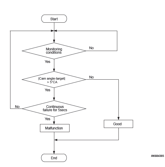
Logic Flow Chart
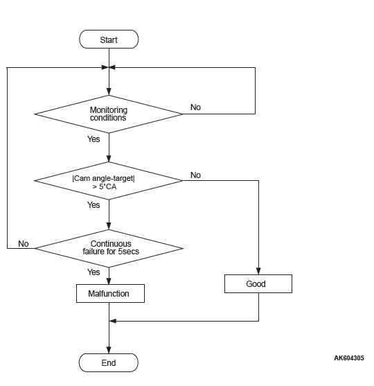
Check Conditions
- More than 20 seconds have passed since the engine starting sequence was completed.
- Engine speed is 1,188 r/min or more.
- Engine coolant temperature is higher than 76ºC (169ºF).
Judgment Criterion
- The difference between the actual intake valve opening timing and the intake valve target opening timing is more than 5 degrees for 5 seconds.
OBD-II DRIVE CYCLE PATTERN
- Refer to Diagnostic Function − OBD-II Drive Cycle − Pattern 20.
TROUBLESHOOTING HINTS (The most likely causes for this code to be set are:)
- Intake engine oil control valve failed.
- Oil passage of variable valve timing control system clogged.
- Intake variable valve timing sprocket operation mechanism stuck.
- ECM failed.
DIAGNOSIS
Required Special Tools
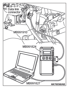
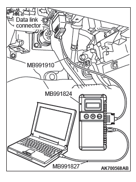
- MB991958: Scan tool (M.U.T.-III Sub Assembly)
- MB991824: V.C.I.
- MB991827: USB Cable
- MB991910: Main Harness A
STEP 1. Using scan tool MB991958, read the diagnostic trouble code (DTC).
CAUTION
To prevent damage to scan tool MB991958, always turn the ignition switch to the "LOCK" (OFF) position before connecting or disconnecting scan tool MB991958.
- Connect scan tool MB991958 to the data link connector.
- Turn the ignition switch to the "ON" position.
- Set scan tool MB991958, read the DTC.
- Turn the ignition switch to the "LOCK" (OFF) position.
Q: Is the diagnostic trouble code other than P0011 set?
YES : Refer to, Diagnostic Trouble Code Chart.
NO : Go to Step 2.
STEP 2. Check intake engine oil control valve itself.
- Check intake engine oil control valve itself (Refer to Engine Oil Control Valve Check).
Q: Is the check result normal?
YES : Go to Step 3.
NO : Replace intake engine oil control valve. Then go to Step 6.
STEP 3. Check oil passage of intake variable valve timing control system for being clogged.
Q: Is the check result normal?
YES : Go to Step 4.
NO : Repair it. Then go to Step 6.
STEP 4. Check intake variable valve timing sprocket operation mechanism for being stuck.
Q: Is the check result normal?
YES : Go to Step 5.
NO : Repair it. Then go to Step 6.
STEP 5. Check the trouble symptoms.
- Carry out test drive with the drive cycle pattern. Refer to Diagnostic Function − OBD-II Drive Cycle − Pattern 20.
- Check the diagnostic trouble code (DTC).
Q: Is DTC P0011 set?
YES : Replace the ECM. When the ECM is replaced, register the ID code. Refer to GROUP 42B, Diagnosis − ID Code Registration Judgment Table <Vehicles with KOS> or GROUP 42C, Diagnosis − ID Codes Registration Judgment Table <Vehicles with WCM>. Then go to Step 6.
NO : It can be assumed that this malfunction is intermittent.
Refer to GROUP 00, How to Use Troubleshooting/Inspection Service Points − How to Cope with Intermittent Malfunctions.
STEP 6. Test the OBD-II drive cycle.
- Carry out a test drive with the drive cycle pattern. Refer to Diagnostic Function − OBD-II Drive Cycle − Pattern 20.
- Check the diagnostic trouble code (DTC).
Q: Is DTC P0011 set?
YES : Retry the troubleshooting.
NO : The inspection is complete.
DTC P0013: Exhaust Engine Oil Control Valve Circuit
EXHAUST ENGINE OIL CONTROL VALVE CIRCUIT
CIRCUIT OPERATION
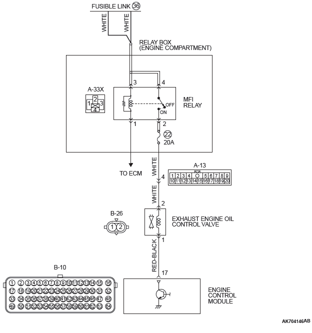
- The exhaust engine oil control valve power is supplied from the MFI relay (terminal No. 2).
- The ECM controls ground exhaust engine oil control valve by turning the power transistor in the ECM "ON" and "OFF".
TECHNICAL DESCRIPTION
- The exhaust engine oil control valve changes the phase angle to operate the MIVEC system in the advance or the retard side in accordance with signals from the ECM.
DESCRIPTIONS OF MONITOR METHODS
Exhaust engine oil control valve circuit current is less than specified value.
MONITOR EXECUTION
Continuous
ONITOR EXECUTION CONDITIONS (Other monitor and Sensor)
Other Monitor (There is no temporary DTC stored in memory for the item monitored below)
- Not applicable
Sensor (The sensor below is determined to be normal)
- Camshaft position sensor
- Crankshaft position sensor
- Engine coolant temperature sensor
- Throttle position sensor
- Engine oil control valve
DTC SET CONDITIONS
Logic Flow Chart
Check Conditions
- Ignition switch is "ON" position.
- Battery positive voltage is between 10 and 16.5 volts.
- ON duty cycle of the exhaust engine oil control valve circuit is higher than 20 percent.
Judgement Criterion
- The ECM terminal current of exhaust engine oil control valve circuit is less than 0.1 ampere for 2 seconds.
Check Conditions
- Ignition switch is "ON" position
- Battery positive voltage is between 10 and 16.5 volts.
Judgement Criterion
- The ECM terminal current of exhaust engine oil control valve circuit is higher than 2.9 amperes for 0.1 second.
OBD-II DRIVE CYCLE PATTERN
- Refer to Diagnostic Function − OBD-II Drive Cycle − Pattern 20.
TROUBLESHOOTING HINTS (The most likely causes for this code to be set are:)
- Exhaust engine oil control valve failed.
- Open or shorted exhaust engine oil control valve circuit, harness damage, or connector damage.
- ECM failed.
DIAGNOSIS
Required Special Tools:
- MB992110:Power Plant ECU CHeck Harness
STEP 1. Check harness connector B-26 at the exhaust engine oil control valve for damage.
Q: Is the harness connector in good condition?
YES : Go to Step 2.
NO : Repair or replace it. Refer to GROUP 00E, Harness Connector Inspection. Then go to Step 10.
STEP 2. Check the exhaust engine oil control valve.
- Disconnect the exhaust engine oil control valve connector B-26.
- Measure the resistance between exhaust engine oil control valve side connector terminal No. 1 and No. 2.
Standard value: 6.9 − 7.9 ohms [at 20ºC (68ºF) ]
Q: Is the measured resistance between 6.9 and 7.9 ohms [at 20ºC (68ºF) ]?
YES : Go to Step 3.
NO : Replace the exhaust engine oil control valve. Then go to Step 10.
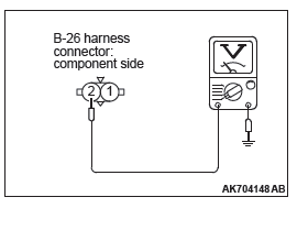
STEP 3. Measure the power supply voltage at exhaust engine oil control valve harness side connector B-26.
- Disconnect the connector B-26 and measure at the harness side.
- Turn the ignition switch to the "ON" position.
- Measure the voltage between terminal No. 2 and ground.
- Voltage should be battery positive voltage.
- Turn the ignition switch to the "LOCK" (OFF) position.
Q: Is battery positive voltage (approximately 12 volts) present?
YES : Go to Step 5.
NO : Go to Step 4.
STEP 4. Check harness connector A-33X at MFI relay for damage.
Q: Is the harness connector in good condition?
YES : Check harness connector A-13 at intermediate connector for damage, and repair or replace as required. Refer to GROUP 00E, Harness Connector Inspection. If intermediate connector is in good condition, repair harness wire between MFI relay connector A-33X (terminal No. 2) and exhaust engine oil control valve connector B-26 (terminal No.2) because of open circuit or short circuit to ground.
Then go to Step 10.
NO : Repair or replace it. Refer to GROUP 00E, Harness Connector Inspection. Then go to Step 10.
STEP 5. Check harness connector B-10 at ECM for damage.
Q: Is the harness connector in good condition?
YES : Go to Step 6.
NO : Repair or replace it. Refer to GROUP 00E, Harness Connector Inspection. Then go to Step 10.
STEP 6. Measure the power supply voltage at ECM connector B-10 by using power plant ECU check harness special tool MB992110.
- Disconnect all ECM connectors. Connect the power plant ECU check harness special tool MB992110 between the separated connectors.
- Turn the ignition switch to the "ON" position.

- Measure the voltage between terminal No. 17 and ground.
- Voltage should be battery positive voltage.
- Turn the ignition switch to the "LOCK" (OFF) position.
Q: Is battery positive voltage (approximately 12 volts) present?
YES : Go to Step 7.
NO : Repair harness wire between exhaust engine oil control valve connector B-26 (terminal No. 1) and ECM connector B-10 (terminal No. 17) because of open circuit or short circuit to ground. Then go to Step 10.
STEP 7. Check for harness damage between MFI relay connector A-33X (terminal No. 2) and exhaust engine oil control valve connector B-26 (terminal No. 2).
NOTE: Check harness after checking intermediate connector A-13. If intermediate connector is damaged, repair or replace it.
Refer to GROUP 00E, Harness Connector Inspection.
Then go to Step 10.
Q: Is the harness wire in good condition?
YES : Go to Step 8.
NO : Repair it. Then go to Step 10.
STEP 8. Check for harness damage between exhaust engine oil control valve connector B-26 (terminal No. 1) and ECM connector B-10 (terminal No. 17).
Q: Is the harness wire in good condition?
YES : Go to Step 9.
NO : Repair it. Then go to Step 10.
STEP 9. Check the trouble symptoms.
- Carry out test drive with the drive cycle pattern. Refer to Diagnostic Function − OBD-II Drive Cycle − Pattern 20.
- Check the diagnostic trouble code (DTC).
Q: Is DTC P0013 set?
YES : Replace the ECM. When the ECM is replaced, register the ID code. Refer to GROUP 42B, Diagnosis − ID Code Registration Judgment Table <Vehicles with KOS> or GROUP 42C, Diagnosis − ID Codes Registration Judgment Table <Vehicles with WCM>. Then go to Step 10.
NO : It can be assumed that this malfunction is intermittent.
Refer to GROUP 00, How to Use Troubleshooting/Inspection Service Points − How to Cope with Intermittent Malfunctions.
STEP 10. Test the OBD-II drive cycle.
- Carry out test drive with the drive cycle pattern. Refer to Diagnostic Function − OBD-II Drive Cycle − Pattern 20.
- Check the diagnostic trouble code (DTC).
Q: Is DTC P0013 set?
YES : Retry the troubleshooting.
NO : The inspection is complete.
DTC P0014: Exhaust Variable Valve Timing System Target Error
TECHNICAL DESCRIPTION
- The ECM checks the variable valve timing system for malfunction.
DESCRIPTIONS OF MONITOR METHODS
The phase angle of the exhaust camshaft is higher than the specified value.
MONITOR EXECUTION
Continuous
MONITOR EXECUTION CONDITIONS (Other monitor and Sensor)
Other Monitor (There is no temporary DTC stored in memory for the item monitored below)
- Not applicable
Sensor (The sensor below is determined to be normal)
- Camshaft position sensor
- Crankshaft position sensor
- Engine coolant temperature sensor
- Throttle position sensor
- Engine oil control valve
DTC SET CONDITIONS
Logic Flow Chart
Check Conditions
- More than 20 seconds have passed since the engine starting sequence was completed.
- Engine speed is 1,188 r/min or more.
- Engine coolant temperature is higher than 76ºC (169ºF).
Judgment Criterion
- The difference between the actual exhaust valve closing timing and the exhaust valve target closing timing is more than 5 degrees for 5 seconds.
OBD-II DRIVE CYCLE PATTERN
- Refer to Diagnostic Function − OBD-II Drive Cycle − Pattern 20.
TROUBLESHOOTING HINTS (The most likely causes for this code to be set are:)
- Exhaust engine oil control valve failed.
- Oil passage of variable valve timing control system clogged.
- Exhaust variable valve timing sprocket operation mechanism stuck.
- ECM failed.
DIAGNOSIS
Required Special Tools
- MB991958: Scan tool (M.U.T.-III Sub Assembly)
- MB991824: V.C.I.
- MB991827: USB Cable
- MB991910: Main Harness A
STEP 1. Using scan tool MB991958, read the diagnostic trouble code (DTC).
CAUTION To prevent damage to scan tool MB991958, always turn the ignition switch to the "LOCK" (OFF) position before connecting or disconnecting scan tool MB991958.
- Connect scan tool MB991958 to the data link connector.
- Turn the ignition switch to the "ON" position.
- Set scan tool MB991958, read the DTC.
- Turn the ignition switch to the "LOCK" (OFF) position.
Q: Is the diagnostic trouble code other than P0014 set?
YES : Refer to, Diagnostic Trouble Code Chart.
NO : Go to Step 2.
STEP 2. Check exhaust engine oil control valve itself.
- Check exhaust engine oil control valve itself (Refer to Engine Oil Control Valve Check).
Q: Is the check result normal?
YES : Go to Step 3.
NO : Replace exhaust engine oil control valve. Then go to Step 6.
STEP 3. Check oil passage of exhaust variable valve timing control system for being clogged.
Q: Is the check result normal?
YES : Go to Step 4.
NO : Repair it. Then go to Step 6.
STEP 4. Check exhaust variable valve timing sprocket operation mechanism for being stuck.
Q: Is the check result normal?
YES : Go to Step 5.
NO : Repair it. Then go to Step 6.
STEP 5. Check the trouble symptoms.
- Carry out test drive with the drive cycle pattern. Refer to Diagnostic Function − OBD-II Drive Cycle − Pattern 20.
- Check the diagnostic trouble code (DTC).
Q: Is DTC P0014 set?
YES : Replace the ECM. When the ECM is replaced, register the ID code. Refer to GROUP 42B, Diagnosis − ID Code Registration Judgment Table <Vehicles with KOS> or GROUP 42C, Diagnosis − ID Codes Registration Judgment Table <Vehicles with WCM>. Then go to Step 6.
NO : It can be assumed that this malfunction is intermittent.
Refer to GROUP 00, How to Use Troubleshooting/Inspection Service Points − How to Cope with Intermittent Malfunctions.
STEP 6. Test the OBD-II drive cycle.
- Carry out a test drive with the drive cycle pattern. Refer to Diagnostic Function − OBD-II Drive Cycle − Pattern 20.
- Check the diagnostic trouble code (DTC).
Q: Is DTC P0014 set?
YES : Retry the troubleshooting.
NO : The inspection is complete.
DTC P0016: Crankshaft/camshaft (intake) Position Sensor Phase Problem
TECHNICAL DESCRIPTION
- The ECM checks the variable valve timing system for malfunction.
DESCRIPTIONS OF MONITOR METHODS
The open timing of the intake valve is faster or slower than the specified value.
MONITOR EXECUTION
Continuous
MONITOR EXECUTION CONDITIONS (Other monitor and Sensor)
Other Monitor (There is no temporary DTC stored in memory for the item monitored below)
- Not applicable
Sensor (The sensor below is determined to be normal)
- Camshaft position sensor
- Crankshaft position sensor
- Engine coolant temperature sensor
- Throttle position sensor
- Engine oil control valve
DTC SET CONDITIONS
Logic Flow Chart
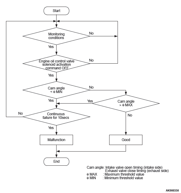
Check Conditions
- Engine speed is between 594 r/min and 1,500 r/min.
- Engine coolant temperature is between 20ºC (68ºF) and 88ºC (190ºF).
- Intake engine oil control valve is "OFF".
- 1 second has elapsed after the above mentions have been met.
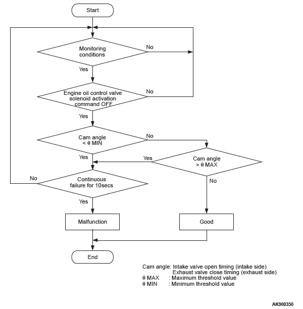
Judgment Criterion
- The open timing of the intake valve is faster than
−7.0 degrees (ATDC) for 10 seconds.
or
- The open timing of the intake valve is slower than 6.1 degrees (ATDC) for 10 seconds.
OBD-II DRIVE CYCLE PATTERN
- Refer to Diagnostic Function − OBD-II Drive Cycle − Pattern 20.
TROUBLESHOOTING HINTS (The most likely causes for this code to be set are:)
- Timing chain in out of place.
- Loose timing chain.
- Intake variable valve timing sprocket tooth coming off.
- ECM failed.
DIAGNOSIS
Required Special Tools
- MB991709: Test Harness
- MB992110: Power Plant ECU Check Harness
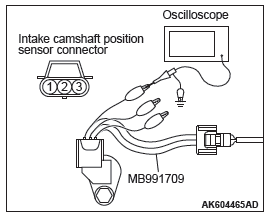
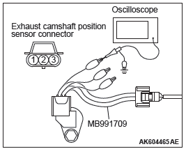
STEP 1. Using the oscilloscope, measure output wave pattern at crankshaft position sensor and intake camshaft position sensor.
- Disconnect the crankshaft position sensor connector B-119 and connect the test harness special tool (MB991709) between the separated connectors.
- Connect the oscilloscope probe to the crankshaft position sensor side connector terminal No. 3.
- Disconnect the intake camshaft position sensor connector B-123, and connect test harness special tool (MB991709) between the separated connectors.
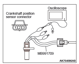
- Connect the oscilloscope probe to the intake camshaft
position sensor side connector terminal No. 3.
NOTE: When measuring with the ECM side connector, disconnect all ECM connectors. Connect the check harness special tool (MB992110) between the separated connectors.
Then connect the oscilloscope probe to the check harness connector terminal No. 8 (crankshaft position sensor) and terminal No. 14 (intake camshaft position sensor).
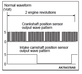
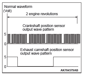
- Start the engine and run at idle.
- Check the waveform.
- The waveform should show a pattern similar to the illustration.
- Turn the ignition switch to the "LOCK" (OFF) position.
Q: Is the waveform normal?
YES : Go to Step 2.
NO : Go to Step 3.
STEP 2. Check the trouble symptoms.
- Carry out a test drive with the drive cycle pattern. Refer to Diagnostic Function − OBD-II Drive Cycle − Pattern 20.
- Check the diagnostic trouble code (DTC).
Q: Is DTC P0016 set?
YES : Replace the ECM. When the ECM is replaced, register the ID code. Refer to GROUP 42B, Diagnosis − ID Code Registration Judgment Table <Vehicles with KOS> or GROUP 42C, Diagnosis − ID Codes Registration Judgment Table <Vehicles with WCM>. Then go to Step 4.
NO : It can be assumed that this malfunction is intermittent.
Refer to GROUP 00, How to Use Troubleshooting/ Inspection Service Points − How to Cope with Intermittent Malfunctions.
STEP 3. Check timing mark on the timing chain.
Q: Is timing chain in out of place?
YES : Repair it. Then initialize the learning value for the elongation of the timing chain. Refer to GROUP 00, Precautions Before Service − Timing Chain Learned Value Reset. Then go to Step 4.
NO : Check the following items, and repair or replace the defective items.
- Check the timing chain loose.
- Check the intake variable valve timing sprocket tooth coming off.
Then initialize the learning value for the elongation of the timing chain. Refer to GROUP 00, Precautions Before Service − Timing Chain Learned Value Reset. Then go to Step 4.
STEP 4. Test the OBD-II drive cycle.
- Carry out a test drive with the drive cycle pattern. Refer to Diagnostic Function − OBD-II Drive Cycle − Pattern 20.
- Check the diagnostic trouble code (DTC).
Q: Is DTC P0016 set?
YES : Retry the troubleshooting.
NO : The inspection is complete
DTC P0017: Crankshaft/camshaft (exhaust) Position Sensor Phase Problem
TECHNICAL DESCRIPTION
- The ECM checks the variable valve timing system for malfunction.
DESCRIPTIONS OF MONITOR METHODS
The close timing of the exhaust valve is faster or slower than the specified value.
MONITOR EXECUTION
Continuous
MONITOR EXECUTION CONDITIONS (Other monitor and Sensor)
Other Monitor (There is no temporary DTC stored in memory for the item monitored below)
- Not applicable
Sensor (The sensor below is determined to be normal)
- Camshaft position sensor
- Crankshaft position sensor
- Engine coolant temperature sensor
- Throttle position sensor
- Engine oil control valve
DTC SET CONDITIONS
Logic Flow Chart
Check Conditions
- Engine speed is between 594 r/min and 1,500 r/min.
- Engine coolant temperature is between 20ºC (68ºF) and 88ºC (190ºF).
- Exhaust engine oil control valve is "OFF".
- 1 second has elapsed after the above mentions have been met.
Judgment Criterion
- The close timing of the exhaust valve is faster
than −7.7 degrees (ATDC) for 10 seconds.
or
- The close timing of the exhaust valve is slower than 5.4 degrees (ATDC) for 10 seconds.
OBD-II DRIVE CYCLE PATTERN
- Refer to Diagnostic Function − OBD-II Drive Cycle − Pattern 20.
TROUBLESHOOTING HINTS (The most likely causes for this code to be set are:)
- Timing chain in out of place.
- Loose timing chain.
- Exhaust variable valve timing sprocket tooth coming off.
- ECM failed.
DIAGNOSIS
Required Special Tools
- MB991709: Test Harness
- MB992110: Power Plant ECU Check Harness
STEP 1. Using the oscilloscope, measure output wave pattern at crankshaft position sensor and exhaust camshaft position sensor.
- Disconnect the crankshaft position sensor connector B-119 and connect the test harness special tool (MB991709) between the separated connectors.
- Connect the oscilloscope probe to the crankshaft position sensor side connector terminal No. 3.
- Disconnect the exhaust camshaft position sensor connector B-22, and connect test harness special tool (MB991709) between the separated connectors.
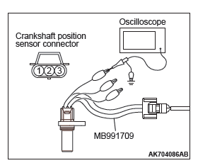
- Connect the oscilloscope probe to the exhaust camshaft
position sensor side connector terminal No. 3.
NOTE: When measuring with the ECM side connector, disconnect all ECM connectors. Connect the check harness special tool (MB992110) between the separated connectors.
Then connect the oscilloscope probe to the check harness connector terminal No. 8 (crankshaft position sensor) and terminal No. 7 (exhaust camshaft position sensor).
- Start the engine and run at idle.
- Check the waveform.
- The waveform should show a pattern similar to the illustration.
- Turn the ignition switch to the "LOCK" (OFF) position.
Q: Is the waveform normal?
YES : Go to Step 2.
NO : Go to Step 3.
STEP 2. Check the trouble symptoms.
- Carry out a test drive with the drive cycle pattern. Refer to Diagnostic Function − OBD-II Drive Cycle − Pattern 20.
- Check the diagnostic trouble code (DTC).
Q: Is DTC P0017 set?
YES : Replace the ECM. When the ECM is replaced, register the ID code. Refer to GROUP 42B, Diagnosis − ID Code Registration Judgment Table <Vehicles with KOS> or GROUP 42C, Diagnosis − ID Codes Registration Judgment Table <Vehicles with WCM>. Then go to Step 4.
NO : It can be assumed that this malfunction is intermittent.
Refer to GROUP 00, How to Use Troubleshooting/ Inspection Service Points − How to Cope with Intermittent Malfunctions.
STEP 3. Check timing mark on the timing chain.
Q: Is timing chain in out of place?
YES : Repair it. Then initialize the learning value for the elongation of the timing chain. Refer to GROUP 00, Precautions Before Service − Timing Chain Learned Value Reset. Then go to Step 4.
NO : Check the following items, and repair or replace the defective items.
- Check the timing chain loose.
- Check the exhaust variable valve timing sprocket tooth coming off.
Then initialize the learning value for the elongation of the timing chain. Refer to GROUP 00, Precautions Before Service − Timing Chain Learned Value Reset. Then go to Step 4.
STEP 4. Test the OBD-II drive cycle.
- Carry out a test drive with the drive cycle pattern. Refer to Diagnostic Function − OBD-II Drive Cycle − Pattern 20.
- Check the diagnostic trouble code (DTC).
Q: Is DTC P0017 set?
YES : Retry the troubleshooting.
NO : The inspection is complete.
DTC P0031: Linear Air-Fuel Ratio Sensor Heater Control Circuit Low
LINEAR AIR-FUEL RATIO SENSOR HEATER CIRCUIT
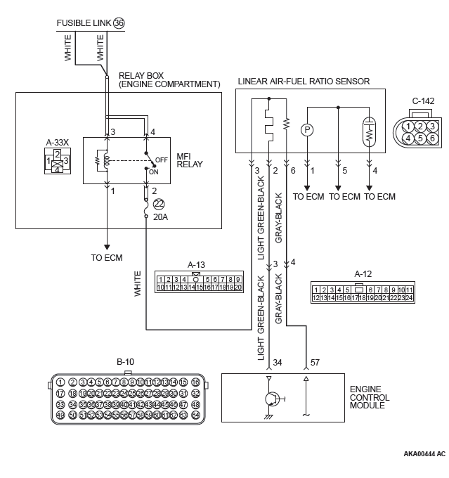
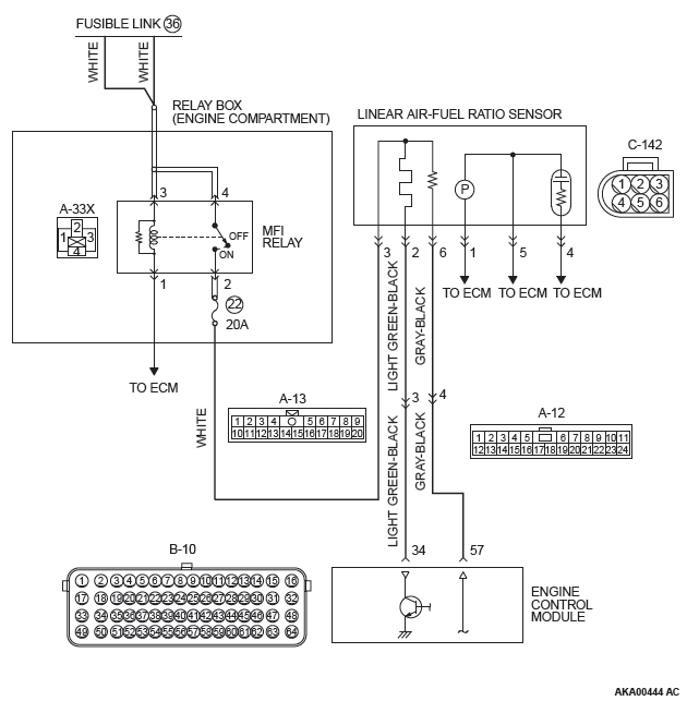
CIRCUIT OPERATION
- Power is supplied from the MFI relay (terminal No. 2) to the linear air-fuel ratio sensor heater.
- The ECM (terminal No. 34) controls continuity to the linear air-fuel ratio sensor heater by turning the power transistor in the ECM "ON" and "OFF".
TECHNICAL DESCRIPTION
- The ECM checks whether the heater current is within a specified range when the heater is energized.
- The ECM checks whether the heater voltage is within a specified range when the heater is not energized.
DESCRIPTIONS OF MONITOR METHODS
Linear air-fuel ratio sensor heater current or voltage is out of specified range.
MONITOR EXECUTION
Continuous
MONITOR EXECUTION CONDITIONS (Other monitor and Sensor)
Other Monitor (There is no temporary DTC stored in memory for the item monitored below)
- Not applicable
Sensor (The sensor below is determined to be normal)
- Not applicable
DTC SET CONDITIONS
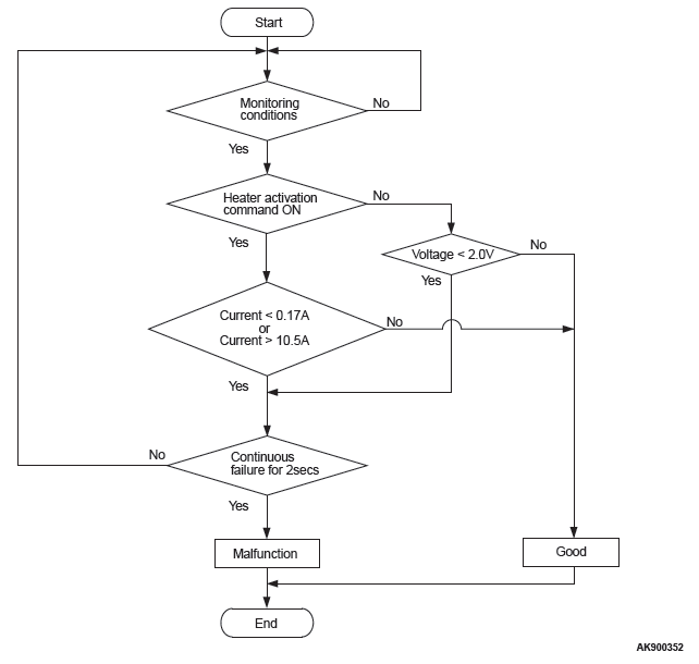
Logic Flow Chart
Check Conditions
- More than 2 seconds have passed since the engine starting sequence was completed.
- While the linear air-fuel ratio sensor heater is on.
- Battery positive voltage is between 11 and 16.5 volts.
Judgement Criterion
- The linear air-fuel ratio sensor heater current has continued to be lower than average 0.17 ampere for 2 seconds.
Check Conditions
- More than 2 seconds have passed since the engine starting sequence was completed.
- While the linear air-fuel ratio sensor heater is off.
- Battery positive voltage is between 11 and 16.5 volts.
Judgement Criterion
- The linear air-fuel ratio sensor heater voltage has continued to be lower than average 2.0 volts for 2 seconds.
OBD-II DRIVE CYCLE PATTERN
- Refer to Diagnostic Function − OBD-II Drive Cycle − Pattern 2.
TROUBLESHOOTING HINTS (The most likely causes for this code to be set are:)
- Open or shorted linear air-fuel ratio sensor heater circuit, harness damage or connector damage.
- Linear air-fuel ratio sensor heater failed.
- ECM failed.
DIAGNOSIS
Required Special Tool:
- MB992110: Power Plant ECU Check Harness
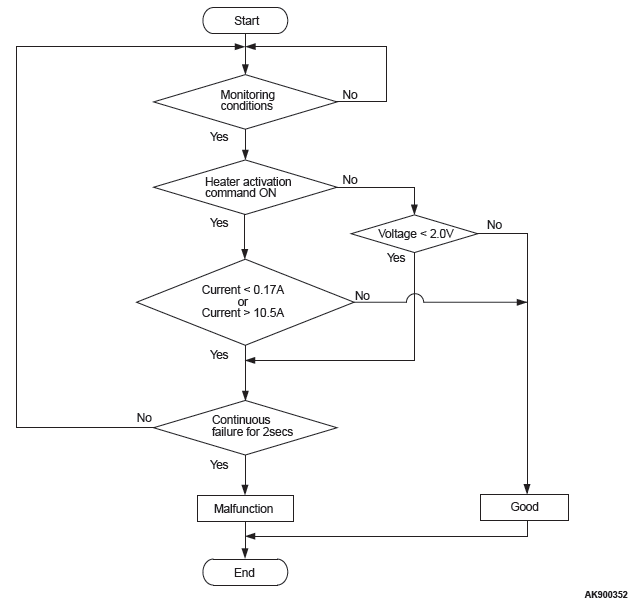
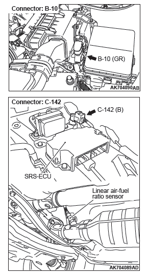
STEP 1. Check harness connector C-142 at linear air-fuel ratio sensor for damage.
Q: Is the harness connector in good condition?
YES : Go to Step 2.
NO : Repair or replace it. Refer to GROUP 00E, Harness Connector Inspection. Then go to Step 11.
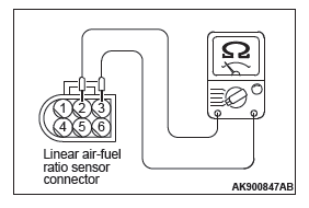
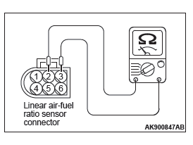
STEP 2. Check the linear air-fuel ratio sensor.
- Disconnect the linear air-fuel ratio sensor connector C-142.
- Measure the resistance between linear air-fuel ratio sensor connector terminal No. 2 and terminal No. 3.
Standard value: 2.3 − 4.2 ohms [at 20ºC (68ºF) ]
Q: Is the measured resistance between 2.3 and 4.2 ohms [at 20ºC (68ºF) ]?
YES : Go to Step 3.
NO : Replace the linear air-fuel ratio sensor. Then go to Step 11.
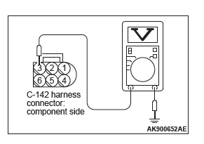
STEP 3. Measure the power supply voltage at linear air-fuel ratio sensor harness side connector C-142.
- Disconnect the connector C-142 and measure at the harness side.
- Turn the ignition switch to the "ON" position.
- Measure the voltage between terminal No. 3 and ground.
- Voltage should be battery positive voltage.
- Turn the ignition switch to the "LOCK" (OFF) position.
Q: Is battery positive voltage (approximately 12 volts) present?
YES : Go to Step 5.
NO : Go to Step 4.
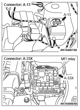
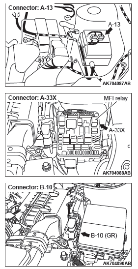
STEP 4. Check harness connector A-33X at MFI relay for damage.
Q: Is the harness connector in good condition?
YES : Repair harness wire between MFI relay connector A-33X (terminal No. 2) and linear air-fuel ratio sensor connector C-142 (terminal No. 3) because of open circuit or short circuit to ground. Then go to Step 11.
NO : Repair or replace it. Refer to GROUP 00E, Harness Connector Inspection. Then go to Step 11.
STEP 5. Check harness connector B-10 at ECM for damage.
Q: Is the harness connector in good condition? YES : Go to Step 6.
NO : Repair or replace it. Refer to GROUP 00E, Harness Connector Inspection. Then go to Step 11.
STEP 6. Measure the power supply voltage at ECM connector B-10 by using power plant ECU check harness special tool MB992110.
- Disconnect all ECM connectors. Connect the power plant ECU check harness special tool MB992110 between the separated connectors.
- Turn the ignition switch to the "ON" position.
- Measure the voltage between terminal No. 34 and ground.
- Voltage should be battery positive voltage.
- Turn the ignition switch to the "LOCK" (OFF) position.
Q: Is battery positive voltage (approximately 12 volts) present?
YES : Go to Step 7.
NO : Check harness connector A-13 at intermediate connector for damage, and repair or replace as required. Refer to GROUP 00E, Harness Connector Inspection. If intermediate connector is in good condition, repair harness wire between linear air-fuel ratio sensor connector C-142 (terminal No. 2) and ECM connector B-10 (terminal No. 34) because of open circuit or short circuit to ground. Then go to Step 11.
STEP 7. Check harness connector A-33X at MFI relay for damage.
Q: Is the harness connector in good condition?
YES : Go to Step 8.
NO : Repair or replace it. Refer to GROUP 00E, Harness Connector Inspection. Then go to Step 11.
STEP 8. Check for harness damage between MFI relay connector A-33X (terminal No. 2) and linear air-fuel ratio sensor connector C-142 (terminal No. 3).
Q: Is the harness wire in good condition?
YES : Go to Step 9.
NO : Repair it. Then go to Step 11.
STEP 9. Check for harness damage between linear air-fuel ratio sensor connector C-142 (terminal No. 2) and ECM connector B-10 (terminal No. 34).
NOTE: Check harness after checking intermediate connector A-13. If intermediate connector is damaged, repair or replace it.
Refer to GROUP 00E, Harness Connector Inspection.
Then go to Step 11.
Q: Is the harness wire in good condition?
YES : Go to Step 10.
NO : Repair it. Then go to Step 11.
STEP 10. Check the trouble symptoms.
- Carry out a test drive with the drive cycle pattern. Refer to Diagnostic Function − OBD-II Drive Cycle − Pattern 2.
- Check the diagnostic trouble code (DTC).
Q: Is DTC P0031 set?
YES : Replace the ECM. When the ECM is replaced, register the ID code. Refer to GROUP 42B, Diagnosis − ID Code Registration Judgment Table <Vehicles with KOS> or GROUP 42C, Diagnosis − ID Codes Registration Judgment Table <Vehicles with WCM>. Then go to Step 11.
NO : It can be assumed that this malfunction is intermittent.
Refer to GROUP 00, How to Use Troubleshooting/Inspection Service Points − How to Cope with Intermittent Malfunctions.
STEP 11. Test the OBD-II drive cycle.
- Carry out a test drive with the drive cycle pattern. Refer to Diagnostic Function − OBD-II Drive Cycle − Pattern 2.
- Check the diagnostic trouble code (DTC).
Q: Is DTC P0031 set?
YES : Retry the troubleshooting.
NO : The inspection is complete.
DTC P0032: Linear Air-Fuel Ratio Sensor Heater Control Circuit High
LINEAR AIR-FUEL RATIO SENSOR HEATER CIRCUIT
CIRCUIT OPERATION
- Power is supplied from the MFI relay (terminal No. 2) to the linear air-fuel ratio sensor heater.
- The ECM (terminal No. 34) controls continuity to the linear air-fuel ratio sensor heater by turning the power transistor in the ECM "ON" and "OFF".
TECHNICAL DESCRIPTION
- The ECM checks whether the heater current is within a specified range when the heater is energized.
DESCRIPTIONS OF MONITOR METHODS
Linear air-fuel ratio sensor heater current is out of specified range.
MONITOR EXECUTION
Continuous
MONITOR EXECUTION CONDITIONS (Other monitor and Sensor)
Other Monitor (There is no temporary DTC stored in memory for the item monitored below)
- Not applicable
Sensor (The sensor below is determined to be normal)
- Not applicable
DTC SET CONDITIONS
Logic Flow Chart
Check Conditions
- More than 2 seconds have passed since the engine starting sequence was completed.
- While the linear air-fuel ratio sensor heater is on.
- Battery positive voltage is between 11 and 16.5 volts.
Judgement Criterion
- The linear air-fuel ratio sensor heater current has continued to be higher than average 10 amperes for 2 seconds.
OBD-II DRIVE CYCLE PATTERN
- Refer to Diagnostic Function − OBD-II Drive Cycle − Pattern 2.
TROUBLESHOOTING HINTS (The most likely causes for this code to be set are:)
- Shorted linear air-fuel ratio sensor heater circuit or connector damage.
- Linear air-fuel ratio sensor heater failed.
- ECM failed.
DIAGNOSIS
STEP 1. Check harness connector C-142 at linear air-fuel ratio sensor for damage.
Q: Is the harness connector in good condition?
YES : Go to Step 2.
NO : Repair or replace it. Refer to GROUP 00E, Harness Connector Inspection. Then go to Step 8.
STEP 2. Check the linear air-fuel ratio sensor.
- Disconnect the linear air-fuel ratio sensor connector C-142.
- Measure the resistance between linear air-fuel ratio sensor connector terminal No. 2 and terminal No. 3.
Standard value: 2.3 − 4.2 ohms [at 20ºC (68ºF) ]
Q: Is the measured resistance between 2.3 and 4.2 ohms [at 20ºC (68ºF) ]?
YES : Go to Step 3.
NO : Replace the linear air-fuel ratio sensor. Then go to Step 8.
STEP 3. Check harness connector A-33X at MFI relay for damage.
Q: Is the harness connector in good condition?
YES : Go to Step 4.
NO : Repair or replace it. Refer to GROUP 00E, Harness Connector Inspection. Then go to Step 8.
STEP 4. Check for short circuit to power supply between MFI relay connector A-33X (terminal No. 2) and linear air-fuel ratio sensor connector C-142 (terminal No. 3).
Q: Is the harness wire in good condition?
YES : Go to Step 5.
NO : Repair it. Then go to Step 8.
STEP 5. Check harness connector B-10 at ECM for damage.
Q: Is the harness connector in good condition?
YES : Go to Step 6.
NO : Repair or replace it. Refer to GROUP 00E, Harness Connector Inspection. Then go to Step 8.
STEP 6. Check for short circuit to power supply between linear air-fuel ratio sensor connector C-142 (terminal No. 2) and ECM connector B-10 (terminal No. 34).
NOTE: Check harness after checking intermediate connector A-13. If intermediate connector is damaged, repair or replace it.
Refer to GROUP 00E, Harness Connector Inspection.
Then go to Step 8.
Q: Is the harness wire in good condition?
YES : Go to Step 7.
NO : Repair it. Then go to Step 8.
STEP 7. Check the trouble symptoms.
- Carry out a test drive with the drive cycle pattern. Refer to Diagnostic Function − OBD-II Drive Cycle − Pattern 2.
- Check the diagnostic trouble code (DTC).
Q: Is DTC P0032 set?
YES : Replace the ECM. When the ECM is replaced, register the ID code. Refer to GROUP 42B, Diagnosis − ID Code Registration Judgment Table <Vehicles with KOS>, Diagnosis − ID Codes Registration Judgment Table <Vehicles with WCM>. Then go to Step 8.
NO : It can be assumed that this malfunction is intermittent.
Refer to GROUP 00, How to Use Troubleshooting/Inspection Service Points − How to Cope with Intermittent Malfunctions.
STEP 8. Test the OBD-II drive cycle.
- Carry out a test drive with the drive cycle pattern. Refer to Diagnostic Function − OBD-II Drive Cycle − Pattern 2.
- Check the diagnostic trouble code (DTC).
Q: Is DTC P0032 set?
YES : Retry the troubleshooting.
NO : The inspection is complete.
DTC P0037: Heated Oxygen Sensor (rear) Heater Control Circuit Low
HEATED OXYGEN SENSOR (REAR) HEATER CIRCUIT

CIRCUIT OPERATION
- Power is supplied from the MFI relay (terminal No. 2) to the heated oxygen sensor (rear) heater.
- The ECM (terminal No. 35) controls continuity to the heated oxygen sensor (rear) heater by turning the power transistor in the ECM "ON" and "OFF".
TECHNICAL DESCRIPTION
- The ECM checks whether the heater current is within a specified range when the heater is energized.
- The ECM checks whether the heater voltage is within a specified range when the heater is not energized.
DESCRIPTIONS OF MONITOR METHODS
Heated oxygen sensor (rear) heater current or voltage is out of specified range.
MONITOR EXECUTION
Continuous
MONITOR EXECUTION CONDITIONS (Other monitor and Sensor)
Other Monitor (There is no temporary DTC stored in memory for the item monitored below)
- Not applicable
Sensor (The sensor below is determined to be normal)
- Not applicable
DTC SET CONDITIONS
Logic Flow Chart
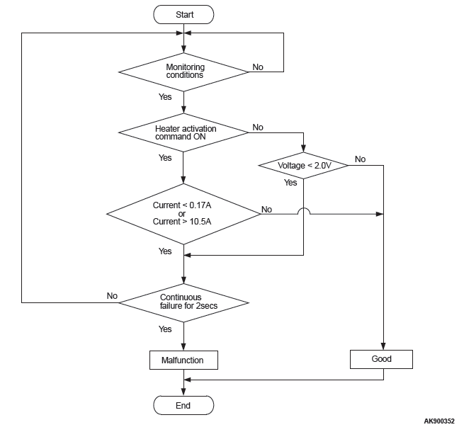
Check Conditions
- More than 2 seconds have passed since the engine starting sequence was completed.
- While the heated oxygen sensor (rear) heater is on.
- Battery positive voltage is between 11 and 16.5 volts.
Judgement Criterion
- The heated oxygen sensor (rear) heater current has continued to be lower than 0.17 ampere for 2 seconds.
Check Conditions
- More than 2 seconds have passed since the engine starting sequence was completed.
- While the heated oxygen sensor (rear) heater is off.
- Battery positive voltage is between 11 and 16.5 volts.
Judgement Criterion
- The heated oxygen sensor (rear) heater voltage has continued to be lower than 2.0 volts for 2 seconds.
OBD-II DRIVE CYCLE PATTERN
- Refer to Diagnostic Function − OBD-II Drive Cycle − Pattern 2.
TROUBLESHOOTING HINTS (The most likely causes for this code to be set are:)
- Open or shorted heated oxygen sensor (rear) heater circuit, harness damage, or connector damage.
- Heated oxygen sensor (rear) heater failed.
- ECM failed.
DIAGNOSIS
Required Special Tools:
- MB991658: Test Harness
- MB992110: Power Plant ECU Check Harness
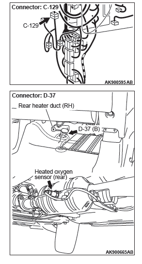
STEP 1. Check harness connector D-37 at the heated oxygen sensor (rear) for damage.
Q: Is the harness connector in good condition?
YES : Go to Step 2.
NO : Repair or replace it. Refer to GROUP 00E, Harness Connector Inspection. Then go to Step 11.
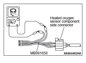
STEP 2. Check the heated oxygen sensor (rear).
- Disconnect heated oxygen sensor (rear) connector D-37 and connect test harness special tool, MB991658, to the connector on the heated oxygen sensor (rear) side.
- Measure the resistance between heated oxygen sensor connector terminal No. 1 and terminal No. 2.
Standard value: 4.5 − 8.0 ohms [at 20ºC (68ºF) ]
Q: Is the measured resistance between 4.5 and 8.0 ohms [at 20ºC (68ºF) ]?
YES : Go to Step 3.
NO : Replace the heated oxygen sensor (rear). Then go to Step 11.
READ NEXT:
 DTC P0053, P0068, P0069, P0101, P0102, P0103, P0106, P0107, P0108
DTC P0053: Linear Air-Fuel Ratio Sensor Heater Resistance
LINEAR AIR-FUEL RATIO SENSOR HEATER CIRCUIT
CIRCUIT OPERATION
Power is supplied from the MFI relay (terminal
No. 2) to the linear air-fu
DTC P0111, P0112, P0113, P0116, P0117, P0118, P0121, P0122, P0123, P0125, P0128,
P0130, P0131
DTC P0111: Intake Air Temperature Circuit Range/Performance Problem
INTAKE AIR TEMPERATURE SENSOR CIRCUIT
CIRCUIT OPERATION
Approximately 5 volts are applied to the intake air
temperature sensor
Fuel Supply
General Information
This fuel system is designed with consideration for
global environment protection to ensure safety at a
collision, reduce weight, and improve reliability and
quality. This system h
SEE MORE:
General Information, Service Precautions
General Information
CAN, an abbreviation for Controller Area Network, is
an ISO-certified international standard for a serial
multiplex communication protocol*. A communication
circuit employing the CAN protocol connects each
electric control module (ECU), and sensor data can
be shared among, which
Fender, Splash Shield, Fuel Filler Lid, Strut Tower Bar
Fender
REMOVAL AND INSTALLATION
Pre-removal and post-installation operation
Splash shield front removal and installation
Front bumper side bracket removal and installation
Headlight assembly removal and installation
Side turn-signal lamp removal and installation
Front deck garnish removal a
