Mitsubishi Outlander: DTC P0111, P0112, P0113, P0116, P0117, P0118, P0121, P0122, P0123, P0125, P0128, P0130, P0131
DTC P0111: Intake Air Temperature Circuit Range/Performance Problem
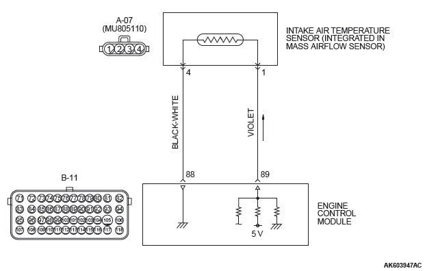
INTAKE AIR TEMPERATURE SENSOR CIRCUIT
CIRCUIT OPERATION
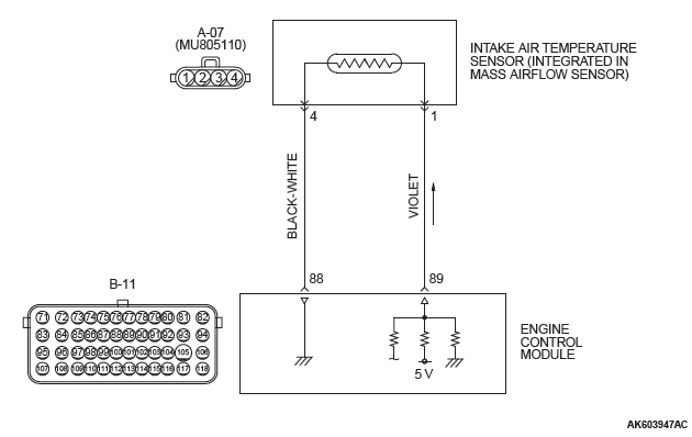
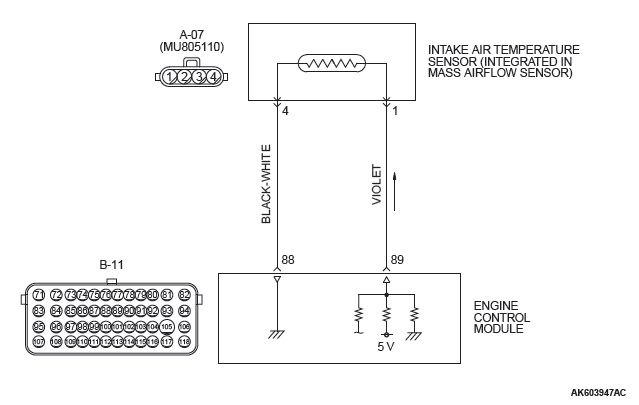
- Approximately 5 volts are applied to the intake air temperature sensor output terminal (terminal No.1) from the ECM (terminal No. 89) via the resistor in the ECM. The ground terminal (terminal No. 4) is grounded with ECM (terminal No. 88).
- The intake air temperature sensor is a negative temperature coefficient type of resistor. When the intake air temperature rises, the resistance decreases.
- The intake air temperature sensor output voltage increases when the resistance increases and decreases when the resistance decreases.
TECHNICAL DESCRIPTION
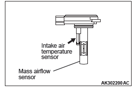
- The intake air temperature sensor converts the intake air temperature to a voltage.
- The ECM checks whether this voltage is within a specified range.
DESCRIPTIONS OF MONITOR METHODS
Intake air temperature sensor output voltage does not change when specified go/stop operations are repeated.
MONITOR EXECUTION
Continuous
MONITOR EXECUTION CONDITIONS (Other monitor and Sensor)
Other Monitor (There is no temporary DTC stored in memory for the item monitored below)
- Not applicable
Sensor (The sensor below is determined to be normal)
- Engine coolant temperature sensor
DTC SET CONDITIONS
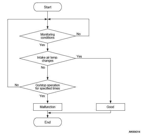
Logic Flow Chart
Check Conditions
- Engine coolant temperature is higher than 76ºC (169ºF).
- Repeat 2 or more times: drive*1, stop*2.
Drive*1: vehicle speed higher than 50 km/h (31 mph) lasting a total of more than 60 seconds.
Stop*2: vehicle speed lower than 1.5 km/h (1.0 mph) lasting more than 30 seconds.
Judgement Criterion
- Changes in the intake air temperature is lower than 1ºC (1.8ºF).
OBD-II DRIVE CYCLE PATTERN
- Refer to Diagnostic Function − OBD-II Drive Cycle − Pattern 8.
TROUBLESHOOTING HINTS (The most likely causes for this code to be set are:)
- Intake air temperature sensor failed.
- Intake air temperature sensor circuit harness damage, or connector damage.
- ECM failed.
DIAGNOSIS
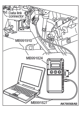
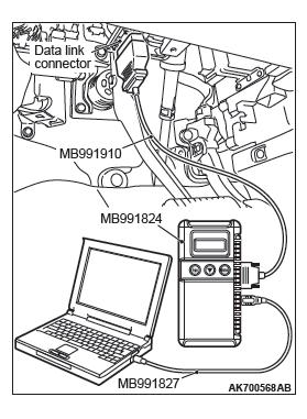
Required Special Tools:
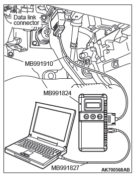
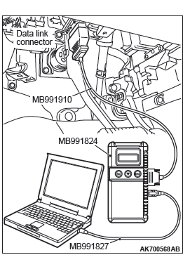
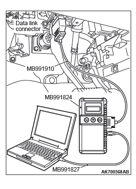
- MB991958: Scan Tool (M.U.T.-III Sub Assembly)
- MB991824: V.C.I.
- MB991827: USB Cable
- MB991910: Main Harness A
STEP 1. Using scan tool MB991958, check data list item 5: Intake Air Temperature Sensor.
CAUTION To prevent damage to scan tool MB991958, always turn the ignition switch to the "LOCK" (OFF) position before connecting or disconnecting scan tool MB991958.
- Connect scan tool MB991958 to the data link connector.
- Remove the mass airflow sensor from the air intake hose.
- Turn the ignition switch to the "ON" position.
- Set scan tool MB991958 to the data reading mode for item 5, Intake Air Temperature Sensor.
- Heating the sensor using a hair drier.
- The indicated temperature increases.
NOTE: Do not allow it to increase over 80ºC (176ºF).
- The indicated temperature increases.
- Turn the ignition switch to the "LOCK" (OFF) position.
- Attach the mass airflow sensor.
Q: Is the sensor operating properly?
YES : It can be assumed that this malfunction is intermittent.
Refer to GROUP 00, How to Use Troubleshooting/Inspection Service Points − How to Cope with Intermittent Malfunctions.
NO : Go to Step 2.
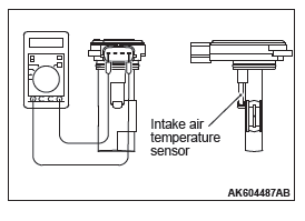
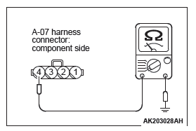
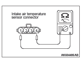
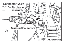
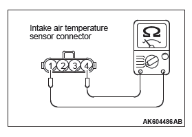
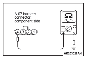
STEP 2. Check the intake air temperature sensor.
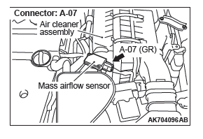
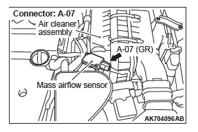
- Disconnect the intake air temperature sensor connector A-07.
- Measure the resistance between intake air temperature sensor side connector terminal No. 1 and No. 4.
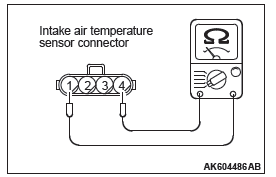
- Measure resistance while heating the sensor using a hair drier.
Standard value:
13 − 17 kΩ [at −20ºC (−4ºF) ]
5.4 − 6.7 kΩ [at 0ºC (32ºF) ]
2.3 − 3.0 kΩ [at 20ºC (68ºF) ]
1.0 − 1.5 kΩ [at 40ºC (104ºF) ]
0.56 − 0.76 kΩ [at 60ºC (140ºF) ]
0.31 − 0.45 kΩ [at 80ºC (176ºF) ]
Q: Is the measured resistance at the standard value?
YES : Go to Step 3.
NO : Replace the mass airflow sensor. Then go to Step 9.
STEP 3. Check harness connector A-07 at the intake air temperature sensor for damage.
Q: Is the harness connector in good condition?
YES : Go to Step 4.
NO : Repair or replace it. Refer to GROUP 00E, Harness Connector Inspection. Then go to Step 9.
STEP 4. Check the continuity at intake air temperature sensor harness side connector A-07.
- Disconnect the connector A-07 and measure at the harness side.
- Check for the continuity between terminal No. 4 and
ground.
- Continuity (2 ohms or less)
Q: Does continuity exist?
YES : Go to Step 7.
NO : Go to Step 5.
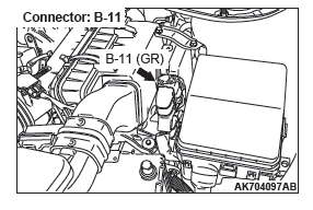
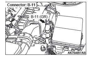
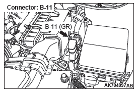
STEP 5. Check harness connector B-11 at ECM for damage.
Q: Is the harness connector in good condition?
YES : Go to Step 6.
NO : Repair or replace it. Refer to GROUP 00E, Harness Connector Inspection. Then go to Step 9.
STEP 6. Check for harness damage between intake air temperature sensor connector A-07 (terminal No. 4) and ECM connector B-11 (terminal No. 88).
Q: Is the harness wire in good condition?
YES : Replace the ECM. When the ECM is replaced, register the ID code. Refer to GROUP 42B, Diagnosis − ID Code Registration Judgment Table <Vehicles with KOS> or GROUP 42C, Diagnosis − ID Codes Registration Judgment Table <Vehicles with WCM>. Then go to Step 9.
NO : Repair it. Then go to Step 9.
STEP 7. Check harness connector B-11 at ECM for damage.
Q: Is the harness connector in good condition?
YES : Go to Step 8.
NO : Repair or replace it. Refer to GROUP 00E, Harness Connector Inspection. Then go to Step 9.
STEP 8. Check for harness damage between intake air temperature sensor connector A-07 (terminal No. 1) and ECM connector B-11 (terminal No. 89).
Q: Is the harness wire in good condition?
YES : Replace the ECM. When the ECM is replaced, register the ID code. Refer to GROUP 42B, Diagnosis − ID Code Registration Judgment Table <Vehicles with KOS> or GROUP 42C, Diagnosis − ID Codes Registration Judgment Table <Vehicles with WCM>. Then go to Step 9.
NO : Repair it. Then go to Step 9.
STEP 9. Test the OBD-II drive cycle.
- Carry out a test drive with the drive cycle pattern. Refer to Diagnostic Function − OBD-II Drive Cycle − Pattern 8.
- Check the diagnostic trouble code (DTC).
Q: Is DTC P0111 set?
YES : Retry the troubleshooting.
NO : The inspection is complete.
DTC P0112: Intake Air Temperature Circuit Low Input
INTAKE AIR TEMPERATURE SENSOR CIRCUIT
CIRCUIT OPERATION
- Approximately 5 volts are applied to the intake air temperature sensor output terminal (terminal No.1) from the ECM (terminal No. 89) via the resistor in the ECM. The ground terminal (terminal No. 4) is grounded with ECM (terminal No. 88).
- The intake air temperature sensor is a negative temperature coefficient type of resistor. When the intake air temperature rises, the resistance decreases.
- The intake air temperature sensor output voltage increases when the resistance increases and decreases when the resistance decreases.
TECHNICAL DESCRIPTION
- The intake air temperature sensor converts the intake air temperature to a voltage.
- The ECM checks whether this voltage is within a specified range.
DESCRIPTIONS OF MONITOR METHODS
Intake air temperature sensor output voltage is out of specified range.
MONITOR EXECUTION
Continuous
MONITOR EXECUTION CONDITIONS (Other monitor and Sensor)
Other Monitor (There is no temporary DTC stored in memory for the item monitored below)
- Not applicable
Sensor (The sensor below is determined to be normal)
- Not applicable
DTC SET CONDITIONS
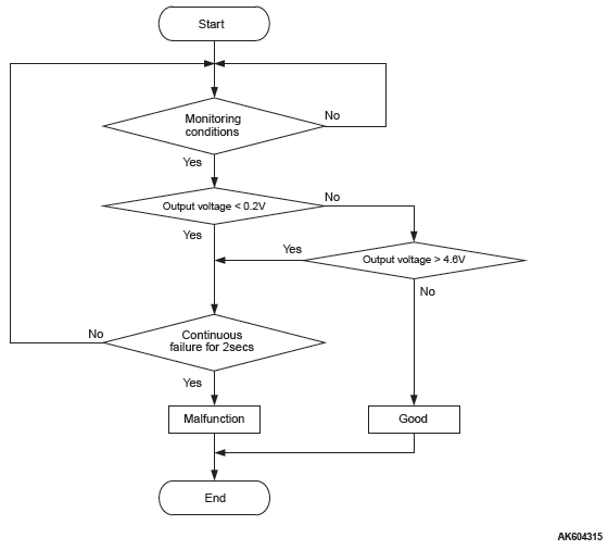
Logic Flow Chart
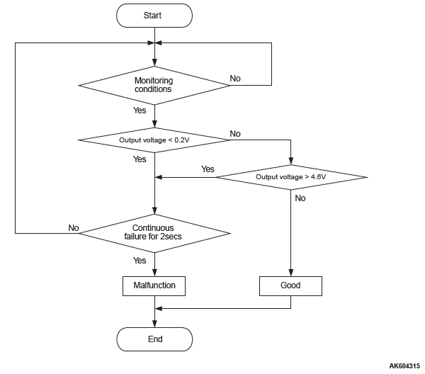
Check Condition
- 2 seconds or more have passed since the engine starting sequence was completed.
Judgement Criterion
- Intake air temperature sensor output voltage has continued to be 0.2 volt or lower [corresponding to an intake air temperature of 115ºC (239ºF) or higher] for 2 seconds.
OBD-II DRIVE CYCLE PATTERN
Refer to Diagnostic Function − OBD-II Drive Cycle − Pattern 23.
TROUBLESHOOTING HINTS (The most likely causes for this code to be set are:)
- Intake air temperature sensor failed.
- Shorted intake air temperature sensor circuit, or connector damage.
- ECM failed.
DIAGNOSIS
Required Special Tools:
- MB991958: Scan Tool (M.U.T.-III Sub Assembly)
- MB991824: V.C.I.
- MB991827: USB Cable
- MB991910: Main Harness A
STEP 1. Using scan tool MB991958, check data list item 5: Intake Air Temperature Sensor.
CAUTION To prevent damage to scan tool MB991958, always turn the ignition switch to the "LOCK" (OFF) position before connecting or disconnecting scan tool MB991958.
- Connect scan tool MB991958 to the data link connector.
- Turn the ignition switch to the "ON" position.
- Set scan tool MB991958 to the data reading mode for item
5, Intake Air Temperature Sensor.
- The intake air temperature and temperature shown with the scan tool should approximately match.
- Turn the ignition switch to the "LOCK" (OFF) position.
Q: Is the sensor operating properly?
YES : It can be assumed that this malfunction is intermittent.
Refer to GROUP 00, How to Use Troubleshooting/Inspection Service Points − How to Cope with Intermittent Malfunctions.
NO : Go to Step 2.
STEP 2. Check harness connector A-07 at the intake air temperature sensor for damage.
Q: Is the harness connector in good condition?
YES : Go to Step 3.
NO : Repair or replace it. Refer to GROUP 00E, Harness Connector Inspection. Then go to Step 6.
STEP 3. Check the intake air temperature sensor.
- Disconnect the intake air temperature sensor connector A-07.
- Measure the resistance between intake air temperature
sensor side connector terminal No. 1 and No. 4.
- There should be continuity. (0.30 − 17 kΩ)
Q: Is the measured resistance between 0.30 and 17 kΩ?
YES : Go to Step 4.
NO : Replace the mass airflow sensor. Then go to Step 6.
STEP 4. Check harness connector B-11 at ECM for damage.
Q: Is the harness connector in good condition?
YES : Go to Step 5.
NO : Repair or replace it. Refer to GROUP 00E, Harness Connector Inspection. Then go to Step 6.
STEP 5. Check for short circuit to ground between intake air temperature sensor connector A-07 (terminal No. 1) and ECM connector B-11 (terminal No. 89).
Q: Is the harness wire in good condition?
YES : Replace the ECM. When the ECM is replaced, register the ID code. Refer to GROUP 42B, Diagnosis − ID Code Registration Judgment Table <Vehicles with KOS> or GROUP 42C, Diagnosis − ID Codes Registration Judgment Table <Vehicles with WCM>. Then go to Step 6.
NO : Repair it. Then go to Step 6.
STEP 6. Test the OBD-II drive cycle.
- Carry out a test drive with the drive cycle pattern. Refer to Diagnostic Function − OBD-II Drive Cycle − Pattern 23.
- Check the diagnostic trouble code (DTC).
Q: Is DTC P0112 set?
YES : Retry the troubleshooting.
NO : The inspection is complete.
DTC P0113: Intake Air Temperature Circuit High Input
INTAKE AIR TEMPERATURE SENSOR CIRCUIT
CIRCUIT OPERATION
- Approximately 5 volts are applied to the intake air temperature sensor output terminal (terminal No.1) from the ECM (terminal No. 89) via the resistor in the ECM. The ground terminal (terminal No. 4) is grounded with ECM (terminal No. 88).
- The intake air temperature sensor is a negative temperature coefficient type of resistor. When the intake air temperature rises, the resistance decreases.
- The intake air temperature sensor output voltage increases when the resistance increases and decreases when the resistance decreases.
TECHNICAL DESCRIPTION
- The intake air temperature sensor converts the intake air temperature to a voltage.
- The ECM checks whether this voltage is within a specified range.
DESCRIPTIONS OF MONITOR METHODS
Intake air temperature sensor output voltage is out of specified range.
MONITOR EXECUTION
Continuous
MONITOR EXECUTION CONDITIONS (Other monitor and Sensor)
Other Monitor (There is no temporary DTC stored in memory for the item monitored below)
- Not applicable
Sensor (The sensor below is determined to be normal)
- Not applicable
DTC SET CONDITIONS
Logic Flow Chart
Check Condition
- 2 seconds or more have passed since the engine starting sequence was completed.
Judgement Criterion
- Intake air temperature sensor output voltage has continued to be 4.6 volts or higher [corresponding to an intake air temperature of −40ºC (−40ºF) or lower] for 2 seconds.
OBD-II DRIVE CYCLE PATTERN
Refer to Diagnostic Function − OBD-II Drive Cycle − Pattern 23.
TROUBLESHOOTING HINTS (The most likely causes for this code to be set are: )
- Intake air temperature sensor failed.
- Open intake air temperature sensor circuit, or connector damage.
- ECM failed.
DIAGNOSIS
Required Special Tools:
- MB991958: Scan Tool (M.U.T.-III Sub Assembly)
- MB991824: V.C.I.
- MB991827: USB Cable
- MB991910: Main Harness A
- MB992110: Power Plant ECU Check Harness
STEP 1. Using scan tool MB991958, check data list item 5: Intake Air Temperature Sensor.
CAUTION To prevent damage to scan tool MB991958, always turn the ignition switch to the "LOCK" (OFF) position before connecting or disconnecting scan tool MB991958.
- Connect scan tool MB991958 to the data link connector.
- Turn the ignition switch to the "ON" position.
- Set scan tool MB991958 to the data reading mode for item
5, Intake Air Temperature Sensor.
- The intake air temperature and temperature shown with the scan tool should approximately match.
- Turn the ignition switch to the "LOCK" (OFF) position.
Q: Is the sensor operating properly?
YES : It can be assumed that this malfunction is intermittent.
Refer to GROUP 00, How to Use Troubleshooting/Inspection Service Points − How to Cope with Intermittent Malfunctions.
NO : Go to Step 2.
STEP 2. Check harness connector A-07 at the intake air temperature sensor for damage.
Q: Is the harness connector in good condition?
YES : Go to Step 3.
NO : Repair or replace it. Refer to GROUP 00E, Harness Connector Inspection. Then go to Step 10.
STEP 3. Check the intake air temperature sensor.
- Disconnect the intake air temperature sensor connector A-07.
- Measure the resistance between intake air temperature
sensor side connector terminal No. 1 and No. 4.
- There should be continuity. (0.30 − 17 kΩ)
Q: Is the measured resistance between 0.30 and 17 kΩ?
YES : Go to Step 4.
NO : Replace the mass airflow sensor. Then go to Step 10.
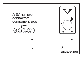
STEP 4. Measure the sensor supply voltage at intake air temperature sensor harness side connector A-07.
- Disconnect the connector A-07 and measure at the harness side.
- Turn the ignition switch to the "ON" position.
- Measure the voltage between terminal No. 1 and ground.
- Voltage should be between 4.5 and 4.9 volts.
- Turn the ignition switch to the "LOCK" (OFF) position.
Q: Is the measured voltage between 4.5 and 4.9 volts?
YES : Go to Step 7.
NO : Go to Step 5.
STEP 5. Check harness connector B-11 at ECM for damage.
Q: Is the harness connector in good condition?
YES : Go to Step 6.
NO : Repair or replace it. Refer to GROUP 00E, Harness Connector Inspection. Then go to Step 10.
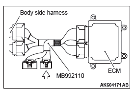
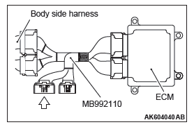
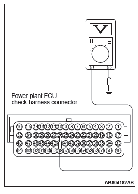
STEP 6. Measure the sensor supply voltage at ECM connector B-11 by using power plant ECU check harness special tool MB992110.
- Disconnect all ECM connectors. Connect the power plant ECU check harness special tool MB992110 between the separated connectors.
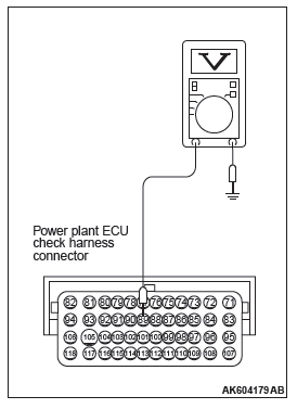
- Disconnect the intake air temperature sensor connector A-07.
- Turn the ignition switch to the "ON" position.
- Measure the voltage between terminal No. 89 and ground.
- Voltage should be between 4.5 and 4.9 volts.
- Turn the ignition switch to the "LOCK" (OFF) position.
Q: Is the measured voltage between 4.5 and 4.9 volts?
YES : Repair harness wire between intake air temperature sensor connector A-07 (terminal No. 1) and ECM connector B-11 (terminal No. 89) because of open circuit. Then go to Step 10.
NO : Replace the ECM. When the ECM is replaced, register the ID code. Refer to GROUP 42B, Diagnosis − ID Code Registration Judgment Table <Vehicles with KOS> or GROUP 42C, Diagnosis − ID Codes Registration Judgment Table <Vehicles with WCM>. Then go to Step 10.
STEP 7. Check the continuity at intake air temperature sensor harness side connector A-07.
- Disconnect the connector A-07 and measure at the harness side.
- Check for the continuity between terminal No. 4 and
ground.
- Continuity (2 ohms or less)
Q: Does continuity exist?
YES : Replace the ECM. When the ECM is replaced, register the ID code. Refer to GROUP 42B, Diagnosis − ID Code Registration Judgment Table <Vehicles with KOS> or GROUP 42C, Diagnosis − ID Codes Registration Judgment Table <Vehicles with WCM>. Then go to Step 10.
NO : Go to Step 8.
STEP 8. Check harness connector B-11 at ECM for damage.
Q: Is the harness connector in good condition?
YES : Go to Step 9.
NO : Repair or replace it. Refer to GROUP 00E, Harness Connector Inspection. Then go to Step 10.
STEP 9. Check for open circuit between intake air temperature sensor connector A-07 (terminal No. 4) and ECM connector B-11 (terminal No. 88).
Q: Is the harness wire in good condition?
YES : Replace the ECM. When the ECM is replaced, register the ID code. Refer to GROUP 42B, Diagnosis − ID Code Registration Judgment Table <Vehicles with KOS> or GROUP 42C, Diagnosis − ID Codes Registration Judgment Table <Vehicles with WCM>. Then go to Step 10.
NO : Repair it. Then go to Step 10.
STEP 10. Test the OBD-II drive cycle.
- Carry out a test drive with the drive cycle pattern. Refer to Diagnostic Function − OBD-II Drive Cycle − Pattern 23.
- Check the diagnostic trouble code (DTC).
Q: Is DTC P0113 set?
YES : Retry the troubleshooting.
NO : The inspection is complete.
DTC P0116: Engine Coolant Temperature Circuit Range/Performance Problem
ENGINE COOLANT TEMPERATURE SENSOR CIRCUIT
CIRCUIT OPERATION
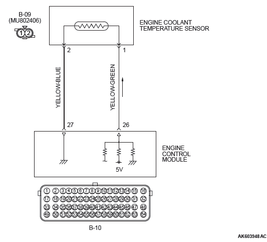
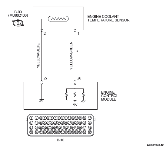
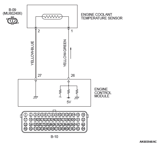
- 5-volt voltage is applied to the engine coolant temperature sensor output terminal (terminal No.1) from the ECM (terminal No. 26) via the resistor in the ECM. The ground terminal (terminal No. 2) is grounded with ECM (terminal No. 27).
- The engine coolant temperature sensor is a negative temperature coefficient type of resistor. It has the characteristic that when the engine coolant temperature rises the resistance decreases.
- The engine coolant temperature sensor output voltage increases when the resistance increases and decreases when the resistance decreases.
TECHNICAL DESCRIPTION
- The engine coolant temperature sensor converts the engine coolant temperature to a voltage and outputs it.
- The ECM checks whether this voltage is within a specified range.
DESCRIPTIONS OF MONITOR METHODS
Engine coolant temperature sensor output voltage does not change for specified period when engine coolant temperature sensor output voltage at engine start is over 7ºC (45ºF).
MONITOR EXECUTION
Once per driving cycle
MONITOR EXECUTION CONDITIONS (Other monitor and Sensor)
Other Monitor (There is no temporary DTC stored in memory for the item monitored below)
- Not applicable
Sensor (The sensor below is determined to be normal)
- Mass airflow sensor
- Intake air temperature sensor
DTC SET CONDITIONS
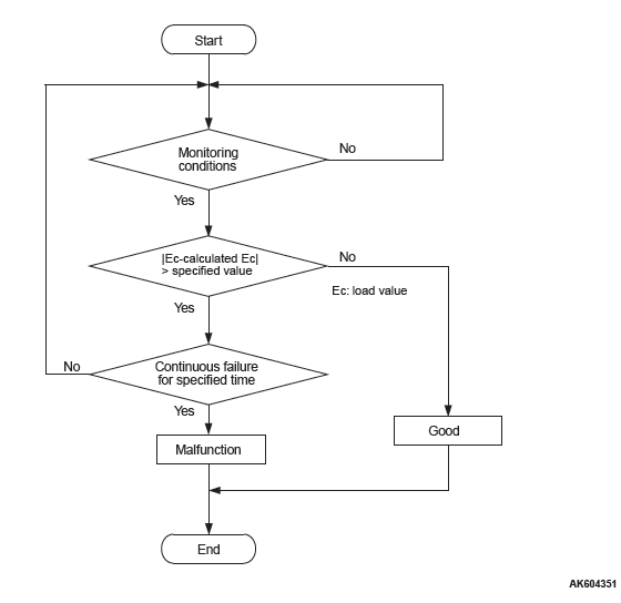
Logic Flow Chart
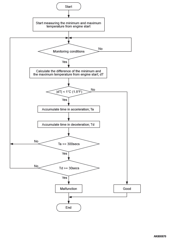
Check Conditions
- Engine coolant temperature was more than 0ºC (32ºF) when the engine started.
- The accumulation is more than 300 seconds during the acceleration having the mass airflow rate of 12 g/sec or more.
- The accumulation is more than 30 seconds during the deceleration having the mass airflow rate of 9 g/sec or less.
Judgement Criteria
- Engine coolant temperature fluctuates within 1ºC (1.8ºF) after 330 seconds have passed since the engine was started.
- However, time is not counted if any of the following conditions are met.
- Intake air temperature is more than 60ºC (140ºF).
- During fuel shut-off operation.
OBD-II DRIVE CYCLE PATTERN
- Refer to Diagnostic Function − OBD-II Drive Cycle − Pattern 9.
TROUBLESHOOTING HINTS (The most likely causes for this code to be set are:)
- Engine coolant temperature sensor failed.
- Engine coolant temperature sensor circuit harness damage, or connector damage.
- ECM failed.
DIAGNOSIS
Required Special Tools:
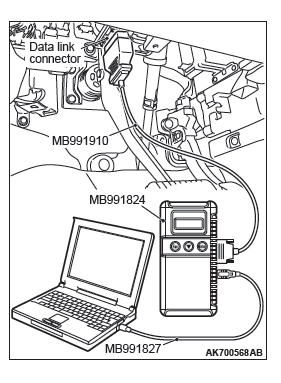
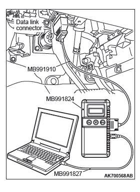
- MB991958: Scan Tool (M.U.T.-III Sub Assembly)
- MB991824: V.C.I.
- MB991827: USB Cable
- MB991910: Main Harness A
STEP 1. Using scan tool MB991958, check data list item 6: Engine Coolant Temperature Sensor.
CAUTION To prevent damage to scan tool MB991958, always turn the ignition switch to the "LOCK" (OFF) position before connecting or disconnecting scan tool MB991958.
- Connect scan tool MB991958 to the data link connector.
- Turn the ignition switch to the "ON" position.
- Set scan tool MB991958 to the data reading mode for item
6, Engine Coolant Temperature Sensor.
- The engine coolant temperature and temperature shown with the scan tool should approximately match.
- Turn the ignition switch to the "LOCK" (OFF) position.
Q: Is the sensor operating properly?
YES : It can be assumed that this malfunction is intermittent.
Refer to GROUP 00, How to Use Troubleshooting/Inspection Service Points − How to Cope with Intermittent Malfunctions.
NO : Go to Step 2.
STEP 2. Check the engine coolant temperature sensor.
Refer to Engine Coolant Temperature Sensor.
Q: Is the engine coolant temperature sensor normal?
YES : Go to Step 3.
NO : Replace the engine coolant temperature sensor. Then go to Step 9.
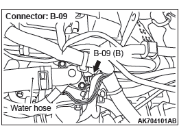
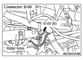
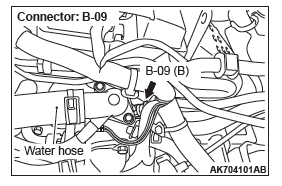
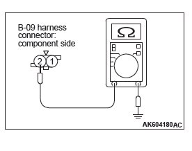
STEP 3. Check harness connector B-09 at the engine coolant temperature sensor for damage.
Q: Is the harness connector in good condition?
YES : Go to Step 4.
NO : Repair or replace it. Refer to GROUP 00E, Harness Connector Inspection. Then go to Step 9.
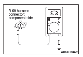
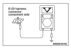
STEP 4. Check the continuity at engine coolant temperature sensor harness side connector B-09.
- Disconnect the connector B-09 and measure at the harness side.
- Check for the continuity between terminal No. 2 and
ground.
- Continuity (2 ohms or less)
Q: Does continuity exist?
YES : Go to Step 7.
NO : Go to Step 5.
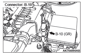
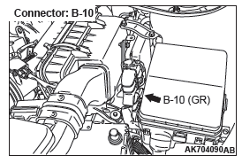
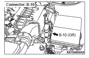
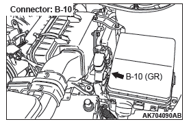
STEP 5. Check harness connector B-10 at ECM for damage.
Q: Is the harness connector in good condition?
YES : Go to Step 6.
NO : Repair or replace it. Refer to GROUP 00E, Harness Connector Inspection. Then go to Step 9.
STEP 6. Check for harness damage between engine coolant temperature sensor connector B-09 (terminal No. 2) and ECM connector B-10 (terminal No. 27).
Q: Is the harness wire in good condition?
YES : Replace the ECM. When the ECM is replaced, register the ID code. Refer to GROUP 42B, Diagnosis − ID Code Registration Judgment Table <Vehicles with KOS> or GROUP 42C, Diagnosis − ID Codes Registration Judgment Table <Vehicles with WCM>. Then go to Step 9.
NO : Repair it. Then go to Step 9.
STEP 7. Check harness connector B-10 at ECM for damage.
Q: Is the harness connector in good condition?
YES : Go to Step 8.
NO : Repair or replace it. Refer to GROUP 00E, Harness Connector Inspection. Then go to Step 9.
STEP 8. Check for harness damage between engine coolant temperature sensor connector B-09 (terminal No. 1) and ECM connector B-10 (terminal No. 26).
Q: Is the harness wire in good condition?
YES : Replace the ECM. When the ECM is replaced, register the ID code. Refer to GROUP 42B, Diagnosis − ID Code Registration Judgment Table <Vehicles with KOS> or GROUP 42C, Diagnosis − ID Codes Registration Judgment Table <Vehicles with WCM>. Then go to Step 9.
NO : Repair it. Then go to Step 9.
STEP 9. Test the OBD-II drive cycle.
- Carry out a test drive with the drive cycle pattern. Refer to Diagnostic Function − OBD-II Drive Cycle − Pattern 9.
- Check the diagnostic trouble code (DTC).
Q: Is DTC P0116 set?
YES : Retry the troubleshooting.
NO : The inspection is complete.
DTC P0117: Engine Coolant Temperature Circuit Low Input
ENGINE COOLANT TEMPERATURE SENSOR CIRCUIT
CIRCUIT OPERATION
- 5-volt voltage is applied to the engine coolant temperature sensor output terminal (terminal No.1) from the ECM (terminal No. 26) via the resistor in the ECM. The ground terminal (terminal No. 2) is grounded with ECM (terminal No. 27).
- The engine coolant temperature sensor is a negative temperature coefficient type of resistor. It has the characteristic that when the engine coolant temperature rises the resistance decreases.
- The engine coolant temperature sensor output voltage increases when the resistance increases and decreases when the resistance decreases.
TECHNICAL DESCRIPTION
- The engine coolant temperature sensor converts the engine coolant temperature to a voltage and outputs it.
- The ECM checks whether this voltage is within a specified range.
DESCRIPTIONS OF MONITOR METHODS
Engine coolant temperature sensor output voltage is out of specified range.
MONITOR EXECUTION
Continuous
MONITOR EXECUTION CONDITIONS (Other monitor and Sensor)
Other Monitor (There is no temporary DTC stored in memory for the item monitored below)
- Not applicable
Sensor (The sensor below is determined to be normal)
- Not applicable
DTC SET CONDITIONS
Logic Flow Chart
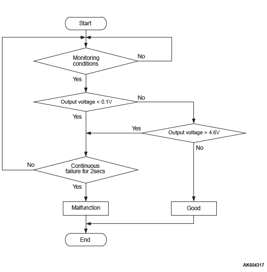
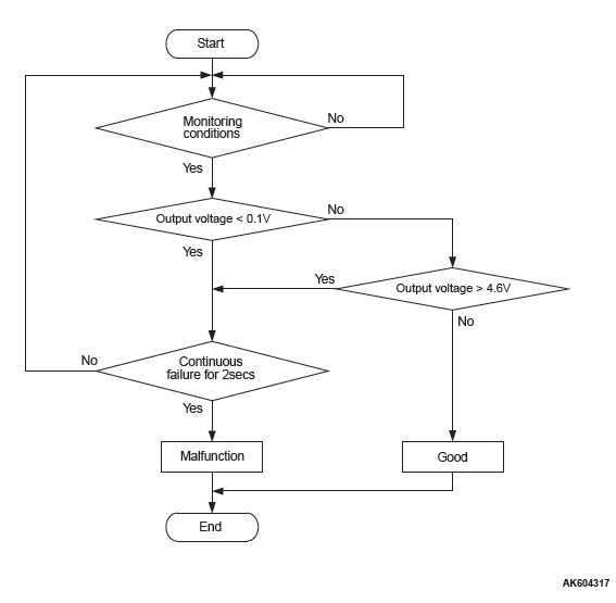
Check Condition
- 2 seconds or more have passed since the engine starting sequence was completed.
Judgement Criterion
- Engine coolant temperature sensor output voltage has continued to be 0.1 volt or lower for 2 seconds.
OBD-II DRIVE CYCLE PATTERN
- Refer to Diagnostic Function − OBD-II Drive Cycle − Pattern 23.
TROUBLESHOOTING HINTS (The most likely causes for this code to be set are:)
- Engine coolant temperature sensor failed.
- Shorted engine coolant temperature sensor circuit, or connector damage.
ECM failed.
DIAGNOSIS
Required Special Tools:
- MB991958: Scan Tool (M.U.T.-III Sub Assembly)
- MB991824: V.C.I.
- MB991827: USB Cable
- MB991910: Main Harness A
STEP 1. Using scan tool MB991958, check data list item 6: Engine Coolant Temperature Sensor.
CAUTION To prevent damage to scan tool MB991958, always turn the ignition switch to the "LOCK" (OFF) position before connecting or disconnecting scan tool MB991958.
- Connect scan tool MB991958 to the data link connector.
- Turn the ignition switch to the "ON" position.
- Set scan tool MB991958 to the data reading mode for item
6, Engine Coolant Temperature Sensor.
- The engine coolant temperature and temperature shown with the scan tool should approximately match.
- Turn the ignition switch to the "LOCK" (OFF) position.
Q: Is the sensor operating properly?
YES : It can be assumed that this malfunction is intermittent.
Refer to GROUP 00, How to Use Troubleshooting/Inspection Service Points − How to Cope with Intermittent Malfunctions.
NO : Go to Step 2.
STEP 2. Check harness connector B-09 at the engine coolant temperature sensor and harness connector B-10 at ECM for damage.
Q: Is the harness connector in good condition?
YES : Go to Step 3.
NO : Repair or replace it. Refer to GROUP 00E, Harness Connector Inspection. Then go to Step 5.
STEP 3. Check for short circuit to ground between engine coolant temperature sensor connector B-09 (terminal No.1) and ECM connector B-10 (terminal No. 26).
Q: Is the harness wire in good condition?
YES : Go to Step 4.
NO : Repair it. Then go to Step 5.
STEP 4. Check the engine coolant temperature sensor.
Refer to Engine Coolant Temperature Sensor.
Q: Is the engine coolant temperature sensor normal?
YES : Replace the ECM. When the ECM is replaced, register the ID code. Refer to GROUP 42B, Diagnosis − ID Code Registration Judgment Table <Vehicles with KOS> or GROUP 42C, Diagnosis − ID Codes Registration Judgment Table <Vehicles with WCM>. Then go to Step 5.
NO : Replace the engine coolant temperature sensor. Then go to Step 5.
STEP 5. Test the OBD-II drive cycle.
- Carry out a test drive with the drive cycle pattern. Refer to Diagnostic Function − OBD-II Drive Cycle − Pattern 23.
- Check the diagnostic trouble code (DTC).
Q: Is DTC P0117 set?
YES : Retry the troubleshooting.
NO : The inspection is complete.
DTC P0118: Engine Coolant Temperature Circuit High Input
ENGINE COOLANT TEMPERATURE SENSOR CIRCUIT
CIRCUIT OPERATION
- 5-volt voltage is applied to the engine coolant temperature sensor output terminal (terminal No.1) from the ECM (terminal No. 26) via the resistor in the ECM. The ground terminal (terminal No. 2) is grounded with ECM (terminal No. 27).
- The engine coolant temperature sensor is a negative temperature coefficient type of resistor. It has the characteristic that when the engine coolant temperature rises the resistance decreases.
- The engine coolant temperature sensor output voltage increases when the resistance increases and decreases when the resistance decreases.
TECHNICAL DESCRIPTION
- The engine coolant temperature sensor converts the engine coolant temperature to a voltage and outputs it.
- The ECM checks whether this voltage is within a specified range.
DESCRIPTIONS OF MONITOR METHODS
Engine coolant temperature sensor output voltage is out of specified range.
MONITOR EXECUTION
Continuous
MONITOR EXECUTION CONDITIONS (Other monitor and Sensor)
Other Monitor (There is no temporary DTC stored in memory for the item monitored below)
- Not applicable
Sensor (The sensor below is determined to be normal)
- Not applicable
DTC SET CONDITIONS
Logic Flow Chart
Check Condition
- 2 seconds or more have passed since the engine starting sequence was completed.
Judgement Criterion
- Engine coolant temperature sensor output voltage has continued to be 4.6 volts or higher for 2 seconds.
OBD-II DRIVE CYCLE PATTERN
- Refer to Diagnostic Function−OBD-II Drive Cycle−Pattern 23.
TROUBLESHOOTING HINTS (The most likely causes for this code to be set are: )
- Engine coolant temperature sensor failed.
- Open engine coolant temperature sensor circuit, or connector damage.
- ECM failed.
DIAGNOSIS
Required Special Tools:
- MB991958: Scan Tool (M.U.T.-III Sub Assembly)
- MB991824: V.C.I.
- MB991827: USB Cable
- MB991910: Main Harness A
- MB992110: Power Plant ECU Check Harness
STEP 1. Using scan tool MB991958, check data list item 6: Engine Coolant Temperature Sensor.
CAUTION To prevent damage to scan tool MB991958, always turn the ignition switch to the "LOCK" (OFF) position before connecting or disconnecting scan tool MB991958.
- Connect scan tool MB991958 to the data link connector.
- Turn the ignition switch to the "ON" position.
- Set scan tool MB991958 to the data reading mode for item
6, Engine Coolant Temperature Sensor.
- The engine coolant temperature and temperature shown with the scan tool should approximately match.
- Turn the ignition switch to the "LOCK" (OFF) position.
Q: Is the sensor operating properly?
YES : It can be assumed that this malfunction is intermittent.
Refer to GROUP 00, How to Use Troubleshooting/Inspection Service Points − How to Cope with Intermittent Malfunctions.
NO : Go to Step 2.
STEP 2. Check harness connector B-09 at the engine coolant temperature sensor for damage.
Q: Is the harness connector in good condition?
YES : Go to Step 3.
NO : Repair or replace it. Refer to GROUP 00E, Harness Connector Inspection. Then go to Step 10.
STEP 3. Measure the sensor supply voltage at engine coolant temperature sensor harness side connector B-09.
- Disconnect the connector B-09 and measure at the harness side.
- Turn the ignition switch to the "ON" position.
- Measure the voltage between terminal No. 1 and ground.
- Voltage should be between 4.5 and 4.9 volts.
- Turn the ignition switch to the "LOCK" (OFF) position.
Q: Is the measured voltage between 4.5 and 4.9 volts?
YES : Go to Step 6.
NO : Go to Step 4.
STEP 4. Check harness connector B-10 at ECM for damage.
Q: Is the harness connector in good condition?
YES : Go to Step 5.
NO : Repair or replace it. Refer to GROUP 00E, Harness Connector Inspection. Then go to Step 10.
STEP 5. Measure the sensor supply voltage at ECM connector B-10 by using power plant ECU check harness special tool MB992110.
- Disconnect all ECM connectors. Connect the power plant ECU check harness special tool MB992110 between the separated connectors.
- Disconnect the engine coolant temperature sensor connector B-09.
- Turn the ignition switch to the "ON" position.
- Measure the voltage between terminal No. 26 and ground.
- Voltage should be between 4.5 and 4.9 volts.
- Turn the ignition switch to the "LOCK" (OFF) position.
Q: Is the measured voltage between 4.5 and 4.9 volts?
YES : Repair harness wire between engine coolant temperature sensor connector B-09 (terminal No. 1) and ECM connector B-10 (terminal No. 26) because of open circuit. Then go to Step 10.
NO : Replace the ECM. When the ECM is replaced, register the ID code. Refer to GROUP 42B, Diagnosis − ID Code Registration Judgment Table <Vehicles with KOS> or GROUP 42C, Diagnosis − ID Codes Registration Judgment Table <Vehicles with WCM>. Then go to Step 10.
STEP 6. Check the continuity at engine coolant temperature sensor harness side connector B-09.
- Disconnect the connector B-09 and measure at the harness side.
- Check for the continuity between terminal No. 2 and
ground.
- Continuity (2 ohms or less)
Q: Does continuity exist?
YES : Go to Step 9.
NO : Go to Step 7.
STEP 7. Check harness connector B-10 at ECM for damage.
Q: Is the harness connector in good condition?
YES : Go to Step 8.
NO : Repair or replace it. Refer to GROUP 00E, Harness Connector Inspection. Then go to Step 10.
STEP 8. Check for open circuit between engine coolant sensor connector B-09 (terminal No. 2) and ECM connector B-10 (terminal No. 27).
Q: Is the harness wire in good condition?
YES : Replace the ECM. When the ECM is replaced, register the ID code. Refer to GROUP 42B, Diagnosis − ID Code Registration Judgment Table <Vehicles with KOS> or GROUP 42C, Diagnosis − ID Codes Registration Judgment Table <Vehicles with WCM>. Then go to Step10.
NO : Repair it. Then go to Step 10.
STEP 9. Check the engine coolant temperature sensor.
Refer to Engine Coolant Temperature Sensor.
Q: Is the engine coolant temperature sensor normal?
YES : Replace the ECM. When the ECM is replaced, register the ID code. Refer to GROUP 42B, Diagnosis − ID Code Registration Judgment Table <Vehicles with KOS> or GROUP 42C, Diagnosis − ID Codes Registration Judgment Table <Vehicles with WCM>. Then go to Step 10.
NO : Replace the engine coolant temperature sensor. Then go to Step 10.
STEP 10. Test the OBD-II drive cycle.
- Carry out a test drive with the drive cycle pattern. Refer to Diagnostic Function − OBD-II Drive Cycle − Pattern 23.
- Check the diagnostic trouble code (DTC).
Q: Is DTC P0118 set?
YES : Retry the troubleshooting.
NO : The inspection is complete.
DTC P0121: Throttle Position Sensor (main) Plausibility
TECHNICAL DESCRIPTION
Compare the actual measurement of volumetric efficiency by a mass airflow sensor signal with the volumetric efficiency estimated from a throttle position sensor (main) signal.
MONITOR EXECUTION
Continuous
MONITOR EXECUTION CONDITIONS (Other monitor and Sensor)
Other Monitor (There is no temporary DTC stored in memory for the item monitored below)
- Not applicable
Sensor (The sensor below is determined to be normal)
- Not applicable
DTC SET CONDITIONS
Logic Flow Chart
Check Conditions
- The difference between the actual volumetric efficiency and the volumetric efficiency estimated by the (main) throttle position sensor is 0 percent or more. Or, the volumetric efficiency is 60 percent or less.
- The engine speed is between 750 and 3,000 r/min. Or, the throttle position sensor (main) output voltage is 3 volts or less.
Judgment Criterion
- For 0.4 second, the difference between the actual volumetric efficiency and the volumetric efficiency estimated by the (main) throttle position sensor is 33 percent or more.
OBD-II DRIVE CYCLE PATTERN
Refer to Diagnostic Function − OBD-II Drive Cycle Pattern 17.
TROUBLESHOOTING HINTS (The most likely causes for this code to be set are:)
- Throttle position sensor (main) system failed.
- Intake system vacuum leak.
- ECM failed.
DIAGNOSIS
Required Special Tools:
- MB991958: Scan Tool (M.U.T.-III Sub Assembly)
- MB991824: V.C.I.
- MB991827: USB Cable
- MB991910: Main Harness A
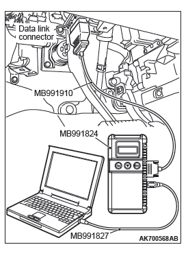
STEP 1. Using scan tool MB991958, read the diagnostic trouble code (DTC).
CAUTION To prevent damage to scan tool MB991958, always turn the ignition switch to the "LOCK" (OFF) position before connecting or disconnecting scan tool MB991958.
- Connect scan tool MB991958 to the data link connector.
- Turn the ignition switch to the "ON" position.
- Read the DTC.
- Turn the ignition switch to the "LOCK" (OFF) position.
Q: Is the diagnostic trouble code other than P0121 set?
YES : Refer to, Diagnostic Trouble Code Chart.
NO : Go to Step 2.
STEP 2. Using scan tool MB991958, check data list item 13: Throttle Position Sensor (main).
- Turn the ignition switch to the "ON" position.
- Detach the intake air hose at the throttle body.
- Disconnect the connector of the throttle position sensor.
- Use test harness special tool (MB991658) to connect only terminals No. 3, No. 4, No. 5, and No. 6.
- Set scan tool MB991958 to the data reading mode for item
13, Throttle Position Sensor (main).
- Output voltage should be between 0.3 and 0.7 volt when the throttle valve is fully closed with your finger.
- Output voltage should be 4.0 volts or more when the throttle valve is fully open with your finger.
- Turn the ignition switch to the "LOCK" (OFF) position.
Q: Is the sensor operating properly?
YES : It can be assumed that this malfunction is intermittent.
Refer to GROUP 00, How to Use Troubleshooting/Inspection Service Points − How to Cope with Intermittent Malfunctions.
NO : Go to Step 3.
STEP 3. Check for intake system vacuum leak.
Q: Are there any abnormalities?
YES : Repair it. Then go to Step 5.
NO : Go to Step 4.
STEP 4. Check the trouble symptoms.
- Carry out a test drive with the drive cycle pattern. Refer to Diagnostic Function − OBD-II Drive Cycle Pattern 17.
- Check the diagnostic trouble code (DTC).
Q: Is DTC P0121 set?
YES : Replace the ECM. When the ECM is replaced, register the ID code. Refer to GROUP 42B, Diagnosis − ID Code Registration Judgment Table <Vehicles with KOS> or GROUP 42C, Diagnosis − ID Codes Registration Judgment Table <Vehicles with WCM>. Then go to Step 5.
NO : It can be assumed that this malfunction is intermittent.
Refer to GROUP 00, How to Use Troubleshooting/Inspection Service Points − How to Cope with Intermittent Malfunctions.
STEP 5. Test the OBD-II drive cycle.
- Carry out a test drive with the drive cycle pattern. Refer to Diagnostic Function − OBD-II Drive Cycle Pattern 17.
- Check the diagnostic trouble code (DTC).
Q: Is DTC P0121 set?
YES : Retry the troubleshooting.
NO : The inspection is complete.
DTC P0122: Throttle Position Sensor (main) Circuit Low Input
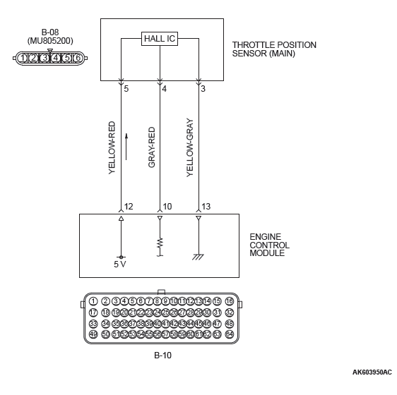
THROTTLE POSITION SENSOR (MAIN) CIRCUIT
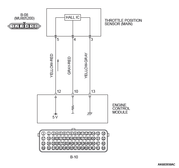
CIRCUIT OPERATION
- A 5-volt power supply is applied on the throttle position sensor (main) power terminal (terminal No. 5) from the ECM (terminal No. 12).
- A voltage that is according to the throttle opening angle is sent to the ECM (terminal No. 10) from the throttle position sensor (main) output terminal (terminal No. 4).
- The ground terminal (terminal No. 3) is grounded with ECM (terminal No. 13).
TECHNICAL DESCRIPTION
- The throttle position sensor (main) outputs voltage which corresponds to the throttle valve opening angle.
- The ECM checks whether the voltage is within a specified range.
DESCRIPTIONS OF MONITOR METHODS
Throttle position sensor (main) output voltage is out of specified range.
MONITOR EXECUTION
Continuous
MONITOR EXECUTION CONDITIONS (Other monitor and Sensor)
Other Monitor (There is no temporary DTC stored in memory for the item monitored below)
- Not applicable
Sensor (The sensor below is determined to be normal)
- Not applicable
DTC SET CONDITIONS
Logic Flow Chart
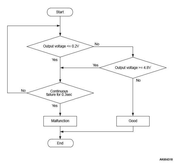
Check Condition
- Ignition switch is "ON" position.
Judgement Criterion
- Throttle position sensor (main) output voltage should be 0.2 volt or less for 0.3 second.
OBD-II DRIVE CYCLE PATTERN
None.
TROUBLESHOOTING HINTS (The most likely causes for this code to be set are:)
- Throttle position sensor failed.
- Shorted throttle position sensor (main) circuit, harness damage, or connector damage.
- ECM failed.
DIAGNOSIS
Required Special Tools:
- MB991958: Scan tool (M.U.T.-III Sub Assembly)
- MB991824: V.C.I.
- MB991827: USB Cable
- MB991910: Main Harness A
- MB991658: Test Harness
STEP 1. Using scan tool MB991958, check data list item 13: Throttle Position Sensor (main).
CAUTION To prevent damage to scan tool MB991958, always turn the ignition switch to the "LOCK" (OFF) position before connecting or disconnecting scan tool MB991958.
- Connect scan tool MB991958 to the data link connector.
- Turn the ignition switch to the "ON" position.
- Detach the intake air hose at the throttle body.
- Disconnect the connector of the throttle position sensor.
- Use test harness special tool (MB991658) to connect only terminals No. 3, No. 4, No. 5, and No. 6.
- Set scan tool MB991958 to the data reading mode for item
13, Throttle Position Sensor (main).
- Output voltage should be between 0.3 and 0.7 volt when the throttle valve is fully closed with your finger.
- Output voltage should be 4.0 volts or more when the throttle valve is fully open with your finger.
- Turn the ignition switch to the "LOCK" (OFF) position.
Q: Is the sensor operating properly?
YES : It can be assumed that this malfunction is intermittent.
Refer to GROUP 00, How to Use Troubleshooting/Inspection Service Points − How to Cope with Intermittent Malfunctions.
NO : Go to Step 2.
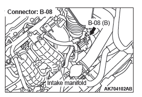
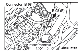
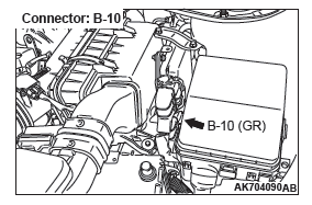
STEP 2. Check harness connector B-08 at throttle position sensor and harness connector B-10 at ECM for damage.
Q: Is the harness connector in good condition?
YES : Go to Step 3.
NO : Repair or replace it. Refer to GROUP 00E, Harness Connector Inspection. Then go to Step 7
STEP 3. Check for harness damage between throttle position sensor connector B-08 (terminal No. 5) and ECM connector B-10 (terminal No. 12).
Q: Is the harness wire in good condition?
YES : Go to Step 4.
NO : Repair it. Then go to Step 7.
STEP 4. Check for short circuit to ground and harness damage between throttle position sensor connector B-08 (terminal No. 4) and ECM connector B-10 (terminal No. 10).
Q: Is the harness wire in good condition?
YES : Go to Step 5.
NO : Repair it. Then go to Step 7.
STEP 5. Using scan tool MB991958, check data list item 13: Throttle Position Sensor (main).
- Turn the ignition switch to the "ON" position.
- Detach the intake air hose at the throttle body.
- Disconnect the connector of the throttle position sensor.
- Use test harness special tool (MB991658) to connect only terminals No. 3, No. 4, No. 5, and No. 6.
- Set scan tool MB991958 to the data reading mode for item
13, Throttle Position Sensor (main).
- Output voltage should be between 0.3 and 0.7 volt when the throttle valve is fully closed with your finger.
- Output voltage should be 4.0 volts or more when the throttle valve is fully open with your finger.
- Turn the ignition switch to the "LOCK" (OFF) position.
Q: Is the sensor operating properly?
YES : It can be assumed that this malfunction is intermittent.
Refer to GROUP 00, How to Use Troubleshooting/Inspection Service Points − How to Cope with Intermittent Malfunctions.
NO : Go to Step 6.
STEP 6. Replace the throttle body assembly.
- Replace the throttle body assembly.
- Turn the ignition switch to the "ON" position.
- After the DTC has been deleted, read the DTC again.
- Turn the ignition switch to the "LOCK" (OFF) position.
Q: Is DTC P0122 set?
YES : Replace the ECM. When the ECM is replaced, register the ID code. Refer to GROUP 42B, Diagnosis − ID Code Registration Judgment Table <Vehicles with KOS> or GROUP 42C, Diagnosis − ID Codes Registration Judgment Table <Vehicles with WCM>. Then go to Step 7.
NO : The inspection is complete.
STEP 7. Using scan tool MB991958, read the diagnostic trouble code (DTC).
- Turn the ignition switch to the "ON" position.
- After the DTC has been deleted, read the DTC again.
- Turn the ignition switch to the "LOCK" (OFF) position.
Q: Is DTC P0122 set?
YES : Retry the troubleshooting.
NO : The inspection is complete.
DTC P0123: Throttle Position Sensor (main) Circuit High Input
THROTTLE POSITION SENSOR (MAIN) CIRCUIT
CIRCUIT OPERATION
- A 5-volt power supply is applied on the throttle
position sensor (main) power terminal (terminal
No. 5) from the ECM
READ NEXT:
 Fuel Supply
General Information
This fuel system is designed with consideration for
global environment protection to ensure safety at a
collision, reduce weight, and improve reliability and
quality. This system h
Intake and Exhaust
Service Specifications
Special Tools
Intake and Exhaust
Diagnosis
INTRODUCTION
Intake leaks usually create driveability issues that
are not obviously related to the intake system.
Exhaust leaks or
SEE MORE:
Fog lamp switch
Front fog lamp switch
The front fog lamps can be operated while the headlamps and tail lamps are on.
Turn the knob in the “ON” direction to turn on the front fog lamps. An indicator
lamp in the instrument cluster will also come on. Turn the knob in the “OFF” direction
to turn off th
Active Stability Control System (ASC)
Service Specifications
Diagnosis
INTRODUCTION TO ASC DIAGNOSIS
The active stability control system (ASC) operates
differently from conventional brake systems. These
differences include sounds, sensations, and vehicle
performance that owners and service technicians
who are not familiar with ASC may
