Mitsubishi Outlander: Intake and Exhaust
Service Specifications
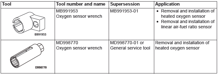
Special Tools
Intake and Exhaust Diagnosis
INTRODUCTION
Intake leaks usually create driveability issues that are not obviously related to the intake system.
Exhaust leaks or abnormal noise is caused by cracks, gaskets and fittings, or by exhaust pipe or muffler damage due to impacts during travel. The exhaust leaks from these sections and causes the exhaust noise to increase. There may be cases when the system contacts the body and vibration noise is generated.
TROUBLESHOOTING STRATEGY
Use these steps to plan your diagnostic strategy. If you follow them carefully, you will be sure that you have exhausted most of the possible ways to find an intake or exhaust system fault.
1. Gather information from the customer.
2. Verify that the condition described by the customer exists.
3. Find the malfunction by following the Symptom Chart.
4. Verify malfunction is eliminated.
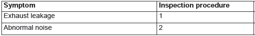
SYMPTOM CHART
SYMPTOM PROCEDURES
Inspection Procedure 1: Exhaust Leakage
DIAGNOSIS
STEP 1. Start the engine. Have an assistant stay in the driver's seat. Raise the vehicle on a hoist.
Have the assistant rev the engine while searching for exhaust leaks.
Q: Is the exhaust leaking?
YES : Go to Step 2.
NO : The procedure is complete.
STEP 2. Check the gasket for cracks, damage.
Q: Is the gasket damaged?
YES : Replace the gasket, then go to Step 1.
NO : Go to Step 3.
STEP 3. Check for loosening in each coupling section.
Q: Is there any loosening in any section?
YES : Tighten, then go to Step 1.
NO : There is no action to be taken.
Inspection Procedure 2: Abnormal Noise
DIAGNOSIS
STEP 1. Start the engine. Have an assistant stay in the drivers seat. Raise the vehicle on a hoist.
Have the assistant rev the engine while searching for exhaust leaks.
Q: Is any abnormal noise generated?
YES : Go to Step 2.
NO : The procedure is complete.
STEP 2. Check for missing parts in the muffler.
Tap the muffler lightly to check for loose baffles, etc.
Q: Are there any missing parts in the muffler?
YES : Replace, then go to Step 1.
NO : Go to Step 3.
STEP 3. Check the hanger for cracks.
Q: Is the hanger cracked?
YES : Replace, then go to Step 1.
NO : Go to Step 4.
STEP 4. Check for interference of the pipes and muffler with the body.
Q: Are the pipes and muffler interfering with the body?
YES : Repair, then go to Step 1.
NO : Go to Step 5.
STEP 5. Check the heat protectors.
Q: Are any heat protectors loose or damaged?
YES : Tighten or replace, then go to Step 1.
NO : Go to Step 6.
STEP 6. Check the pipes and muffler for damage.
Q: Are the pipes and muffler damaged?
YES : Replace, then go to Step 1.
NO : There is no action to be taken.
Air Cleaner
REMOVAL AND INSTALLATION <2.4L ENGINE>
Removal steps
- Air cleaner element
- Air cleaner intake duct
- Breather hose connection
- Air cleaner resonator
- Air cleaner intake hose
- Vacuum hose connection
- Mass airflow sensor connector connection
- Mass airflow sensor
- Air cleaner cover
- Air cleaner body
- Engine control module
- Air cleaner bracket
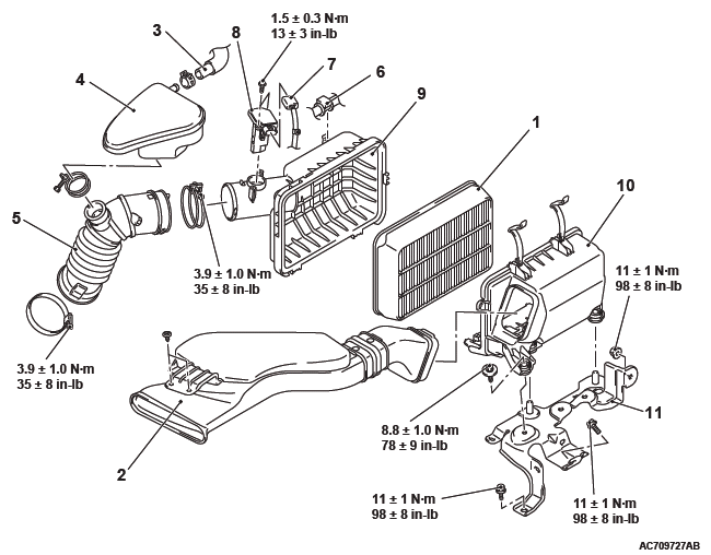
REMOVAL AND INSTALLATION <3.0L ENGINE>
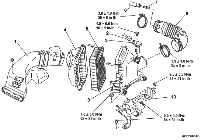
Removal steps
- Air cleaner intake duct
- Mass airflow sensor connector connection
- Mass airflow sensor
- Air cleaner body
- Air cleaner element
- Breather hose connection
- Nipple
- Air cleaner to throttle body duct
- Engine control module
- Air cleaner cover
- Air cleaner bracket
INSTALLATION SERVICE POINT
NIPPLE INSTALLATION
CAUTION Securely install the nipple to the air cleaner to throttle body duct.
Intake Manifold Plenum - 3.0L Engine
REMOVAL AND INSTALLATION
Pre-removal Operation
- Engine Coolant Draining
- Engine Cover Removal
- Strut Tower Bar Removal
- Air Cleaner Assembly Removal
- Throttle Body Assembly Removal
Post-installation Operation
- Throttle Body Assembly Installation
- Air Cleaner Assembly Installation
- Strut Tower Bar Installation
- Engine Cover Installation
- Engine Coolant Refilling
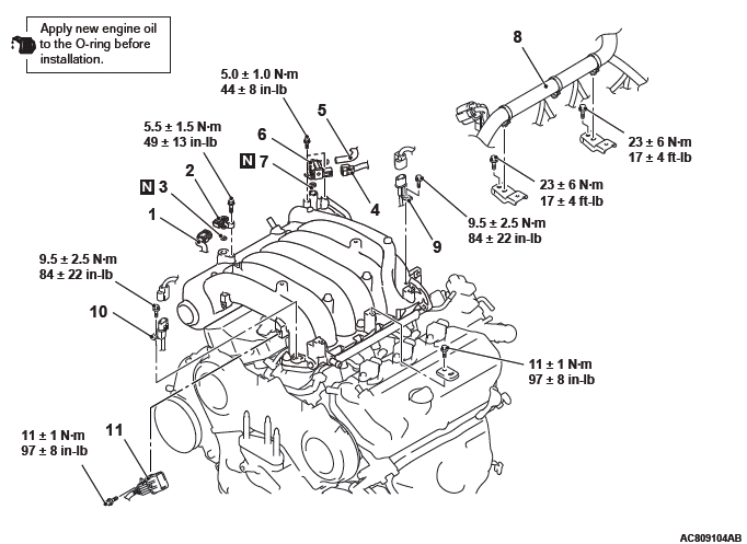
Removal steps
- Manifold absolute pressure sensor connector
- Manifold absolute pressure sensor
- O-ring
- Evaporative emission purge solenoid connector
- Purge hose connection
- Evaporative emission purge solenoid
- O-ring
- Control wiring harness connection
- Right bank knock sensor connector
- Left bank knock sensor connector
- Control wiring harness and injector wiring harness combination connector
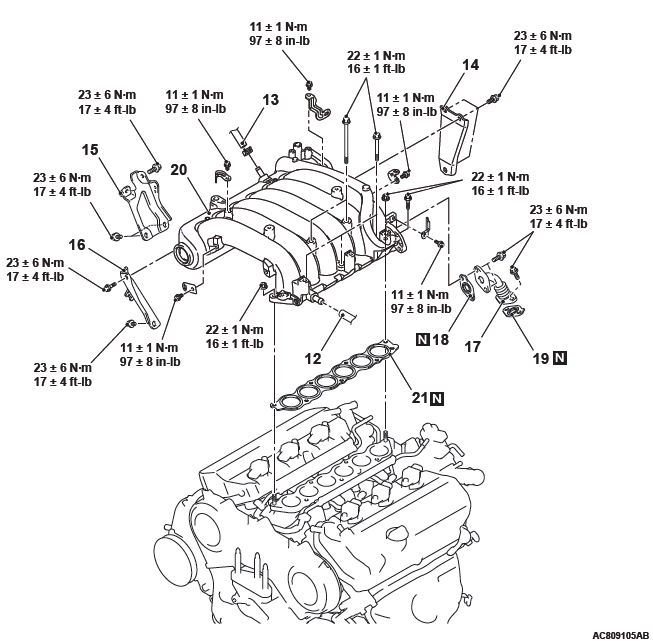
Removal steps
- PCV hose connection
- Brake booster vacuum hose connection
- Throttle body stay
- Intake manifold plenum stay (rear)
- Intake manifold plenum stay (front)
- EGR pipe
- EGR pipe gasket
- EGR pipe gasket
- Intake manifold plenum
- Intake manifold plenum gasket
INSTALLATION SERVICE POINT
MANIFOLD ABSOLUTE PRESSURE SENSOR INSTALLATION
CAUTION
- Install the manifold absolute pressure sensor, taking care not to give a shock to it.
- Do not use a manifold absolute pressure sensor that has fallen down.
Intake Manifold
REMOVAL AND INSTALLATION <2.4L ENGINE>
Pre-removal operation
- Engine Coolant Draining
- Engine Upper Cover Removal
- Generator and Others Belt Removal
- Air Cleaner Intake Hose and Air Cleaner Assembly Removal
- Throttle Body Assembly Removal
- Fuel Injector Removal
- EGR Valve and EGR Valve Stay Removal
Post-installation operation
- EGR Valve and EGR Valve Stay Installation
- Fuel Injector Installation
- Throttle Body Assembly Installation
- Air Cleaner Intake Hose and Air Cleaner Assembly Installation
- Generator and Others Belt Installation
- Engine Upper Cover Installation
- Engine Coolant Refilling
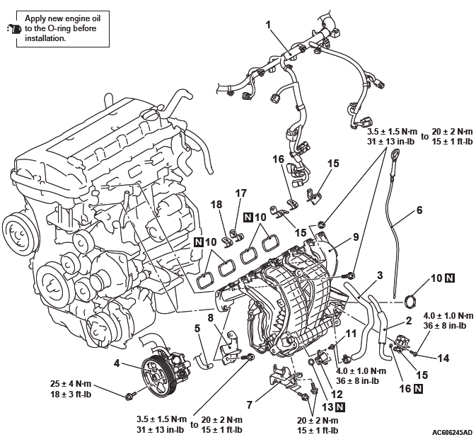
Removal steps
- Control wiring harness connection
- Emission vacuum hose
- Brake booster vacuum hose
- Power steering oil pump assembly
- Rocker cover PCV hose
- Engine oil level gauge
- Intake manifold stay
- Injector protector front
- Intake manifold assembly
- Intake manifold gasket
- Screw
- Manifold absolute pressure sensor
- O-ring
- Screw
- Purge control solenoid valve
- O-ring
- Intake manifold harness bracket
- Engine cover bracket
REMOVAL SERVICE POINT
POWER STEERING OIL PUMP ASSEMBLY REMOVAL
1. With the hose installed, remove the power steering oil pump assembly from the bracket.
2. Tie the removed power steering oil pump assembly with a string at a position where it will not interfere with the removal and installation of the intake manifold.
INSTALLATION SERVICE POINTS
SCREW INSTALLATION
CAUTION Do not over-tighten. As the self-forming-type screw is used, the excessive torque can damage the intake manifold threads.
MANIFOLD ABSOLUTE PRESSURE SENSOR INSTALLATION
CAUTION
- Install the manifold absolute pressure sensor, taking care not to give a shock to it.
- Do not use a manifold absolute pressure sensor that has fallen down.
INTAKE MANIFOLD ASSEMBLY/INJECTOR PROTECTOR FRONT INSTALLATION
Install the intake manifold assembly and the injector protector front, and tighten mounting bolts and nuts temporarily.
NOTE: The tightening of the fuel rail, the intake manifold assembly and the injector protector front and rear has the specified order. Temporarily tighten the intake manifold assembly and injector protector front mounting bolts and nuts (Refer to GROUP 13A, Injector).
REMOVAL AND INSTALLATION <3.0L ENGINE>
Pre-removal Operation
- Fuel Discharge Prevention
- Intake Manifold Plenum Removal
Post-installation Operation
- Intake Manifold Plenum Installation
- Fuel Leakage Inspection
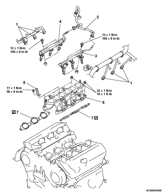
Removal steps
- Injector connector connection
- Fuel high-pressure hose connection
- Left fuel rail and fuel injector assembly
- Right fuel rail and fuel injector assembly
- Harness bracket
- Intake manifold
- Intake manifold gasket
REMOVAL SERVICE POINTS
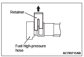
FUEL HIGH-PRESSURE HOSE DISCONNECTION
CAUTION Do not kink the fuel high-pressure hose as it is made of plastics.
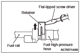
1. Insert a flat-tipped screwdriver [width 6 mm (0.24 inch), thickness 1 mm (0.04 inch) ] to the retainer.
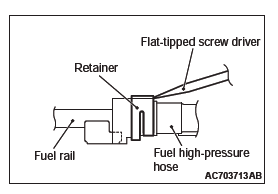
2. Turn the flat-tipped screwdriver approximately 90º to the arrowed direction, and lift the retainer to unlock and disconnect the fuel high-pressure hose.
FUEL RAIL AND INJECTOR ASSEMBLY REMOVAL
CAUTION Do not drop the fuel injector.
Remove the fuel rail with the fuel injectors attached to it.
INSTALLATION SERVICE POINTS
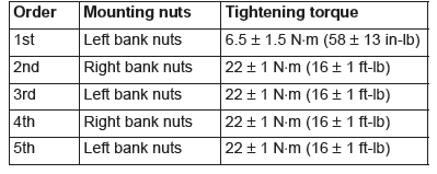
INTAKE MANIFOLD INSTALLATION
1. Coat the intake manifold mounting studs with engine oil.
2. Tighten the intake manifold mounting nuts by the following procedure.
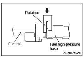
FUEL HIGH-PRESURE HOSE CONNECTION
1. Pull up the lock of fuel high-pressure hose to unlock before installing.
2. Install the fuel high-pressure hose to the fuel rail securely and push the lock of fuel high-pressure hose downward and lock thoroughly.
3. After installing, slightly pull the fuel high-pressure hose and ensure that there is no disengaged fuel high-pressure hose.
Also confirm that there is approximately 1 mm (0.04 inch) play at this time.
INSPECTION
Check the following points; replace the part if a problem is found.
INTAKE MANIFOLD CHECK <2.4L ENGINE>
1. Check for damage or cracking of any part.
2. Clogging of the negative pressure (vacuum) outlet port, or clogging of the exhaust gas recirculation passages.
INTAKE MANIFOLD CHECK <3.0L ENGINE>
1. Check for damage or cracking of any part.
2. Clogging of the negative pressure (vacuum) outlet port, or clogging of the exhaust gas recirculation passages.
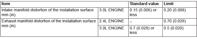
3. Using a straight edge and feeler gauge, check for distortion of the cylinder head installation surface.
Standard value: 0.15 mm (0.006 inch) or less
Limit: 0.20 mm (0.008 inch)
Exhaust Manifold
REMOVAL AND INSTALLATION <2.4L ENGINE>
Pre-removal operation
- Front Exhaust Pipe Removal
- Strut Tower Bar Removal
Post-installation operation
- Strut Tower Bar Installation
- Front Exhaust Pipe Installation
<FWD>
Removal steps
- Exhaust manifold cover (upper)
- Engine hanger
- Exhaust manifold bracket
- Exhaust manifold bracket
- Exhaust manifold bracket
- Exhaust manifold nut
- Exhaust manifold washer
- Exhaust manifold
- Exhaust manifold cover (lower)
- Exhaust manifold gasket
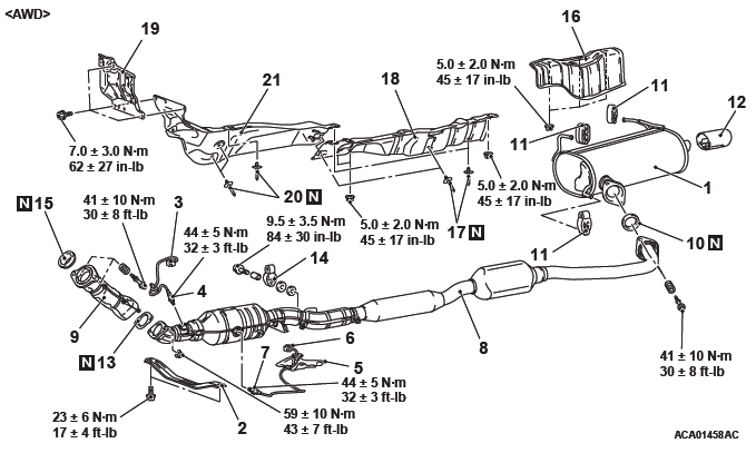
<AWD>
Removal steps
- Exhaust manifold cover (upper)
- Engine hanger
- Exhaust manifold bracket
- Exhaust manifold bracket
- Exhaust manifold nut
- Exhaust manifold washer
- Exhaust manifold
- Exhaust manifold cover (lower)
- Exhaust manifold gasket
REMOVAL SERVICE POINT
EXHAUST MANIFOLD NUT/EXHAUST MANIFOLD WASHER/EXHAUST MANIFOLD/ EXHAUST MANIFOLD COVER (LOWER) REMOVAL
1. Remove the mounting bolts of the exhaust manifold cover (lower) and move them to the position where they will not interfere with the loosening of the exhaust manifold nuts.
2. Loosen the exhaust manifold nuts, and remove the exhaust manifold nuts and the exhaust manifold washers.
3. Remove the exhaust manifold and the exhaust manifold cover (lower) as a set.
INSTALLATION SERVICE POINTS
EXHAUST MANIFOLD COVER (LOWER)/EXHAUST MANIFOLD/EXHAUST MANIFOLD WASHER/EXHAUST MANIFOLD NUT INSTALLATION
1. Install the exhaust manifold cover (lower) to the exhaust manifold (with mounting bolts removed), install the exhaust manifold and the exhaust manifold cover (lower) to the engine as a set.
2. Move the exhaust manifold cover (lower) to the position where it will not interfere with the installation of the exhaust manifold nuts.
3. Install the new exhaust manifold nuts and exhaust manifold washers, and tighten the exhaust manifold nuts to the specified torque.
Tightening torque: 49 +- 5 N*m (36 +- 3 ft-lb)
4. Install the exhaust manifold cover (lower) to the exhaust manifold, and tighten the exhaust manifold cover (lower) mounting bolts to the specified torque.
Tightening torque: 14 +- 1 N*m (124 +- 8 in-lb)
EXHAUST MANIFOLD BRACKET INSTALLATION
1. Temporarily tighten the exhaust manifold bracket with mounting bolts.
2. Make sure that the exhaust manifold bracket is closely contacted with the installation surface of each part.
3. Tighten the mounting bolts to the specified torque.
Tightening torque:
M8: 20 +- 5 N*m (15 +- 3 ft-lb)
M10: 41 +- 10 N*m (30 +- 7 ft-lb)
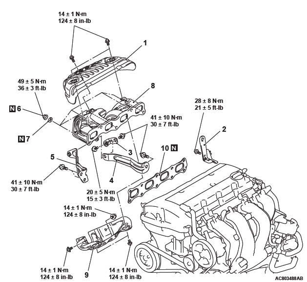
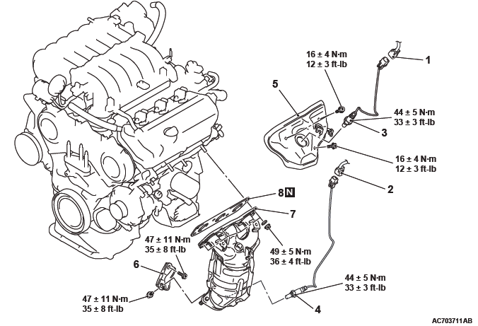
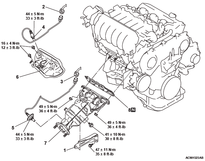
REMOVAL AND INSTALLATION <3.0L ENGINE>
<LEFT BANK>
Pre-removal and Post-installation Operation
- Under Cover Removal and Installation
- Air Duct Removal and Installation
- Front Exhaust Pipe Removal and Installation
Removal steps
- Left bank heated oxygen sensor (Front) connector connection
- Left bank heated oxygen sensor (Rear) connector connection
- Left bank heated oxygen sensor (Front)
- Left bank heated oxygen sensor (Rear)
- Heat protector
- Left exhaust manifold bracket
- Exhaust manifold
- Exhaust manifold gasket
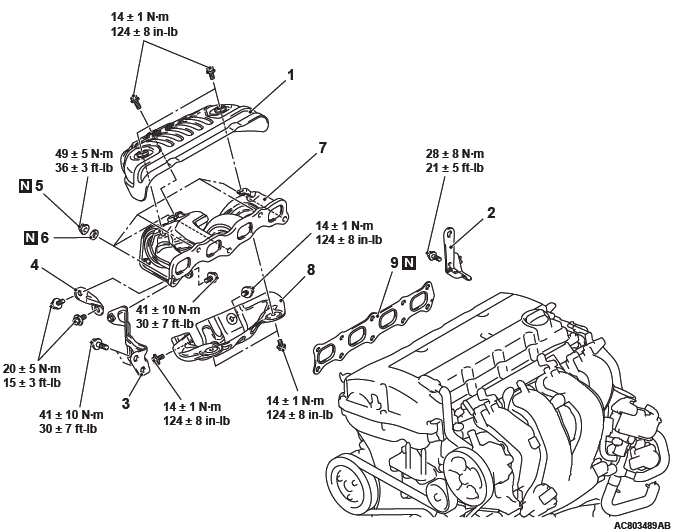
<RIGHT BANK>
Pre-removal and Post-installation Operation
- Air Cleaner Cover and Air Intake Duct Removal and Installation
- Battery Removal and Installation
- Under Cover Removal and Installation
- Front Exhaust Pipe, Center Exhaust Pipe and Front Floor Front Panel Heat Protector Removal and Installation
- Strut Tower Bar Removal and Installation
Removal steps
- Right exhaust manifold bracket <Vehicles without S-AWC>
- Right bank heated oxygen sensor (Front) connector connection
- Right bank heated oxygen sensor (Rear) connector connection
- Right bank heated oxygen sensor (Front)
- Right bank heated oxygen sensor (Rear)
- Heat protector
- Exhaust manifold
- Exhaust manifold gasket
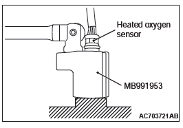
Required Special Tools:
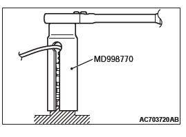
- MB991953: Oxygen Sensor Wrench
- MD998770: Oxygen Sensor Wrench
REMOVAL SERVICE POINTS
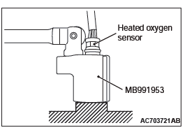
LEFT BANK HEATED OXYGEN SENSOR (FRONT)/RIGHT BANK HEATED OXYGEN SENSOR (FRONT) REMOVAL
Use special tool MB991953 to remove the heated oxygen sensor.
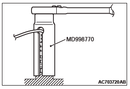
LEFT BANK HEATED OXYGEN SENSOR (REAR)/RIGHT BANK HEATED OXYGEN SENSOR (REAR) REMOVAL
Use special tool MD998770 to remove the heated oxygen sensor.
INSTALLATION SERVICE POINTS
RIGHT BANK HEATED OXYGEN SENSOR (REAR)/LEFT BANK HEATED OXYGEN SENSOR (REAR) INSTALLATION
Use special tool MD998770 to install the heated oxygen sensor.
RIGHT BANK HEATED OXYGEN SENSOR (FRONT)/LEFT BANK HEATED OXYGEN SENSOR (FRONT) INSTALLATION
Use special tool MB991953 to install the heated oxygen sensor.
INSPECTION
Check the following points; replace the part if a problem is found.
EXHAUST MANIFOLD CHECK
1. Check for damage or cracking of any part.
2. Using a straight edge and a feeler gauge, check for distortion of the cylinder head installation surface.
<2.4L ENGINE>
Limit: 0.70 mm (0.028 inch)
<3.0L ENGINE>
Standard value: 0.7 mm (0.028 inch) or less
Limit: 0.5 mm (0.020 inch)
Exhaust Pipe and Main Muffler
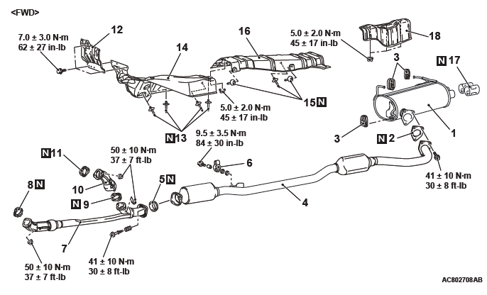
REMOVAL AND INSTALLATION <2.4L ENGINE>

Exhaust main muffler and rear floor panel heat protector removal steps
- Exhaust main muffler
- Seal ring
- Exhaust muffler hanger
- Exhaust tail pipe diffuser
- Rear floor panel heat protector
Center exhaust pipe and front floor panel rear heat protector removal steps
- Backbone brace
- Lower side cover (RH)
- Turn up the passenger's side floor carpet
- Linear air-fuel ratio sensor connection
- Linear air-fuel ratio sensor
- Harness cover
- Front seat assembly (RH)
- Heated oxygen sensor connector connection
- Heated oxygen sensor
- Center exhaust pipe
- Seal ring
- Exhaust pipe gasket
- Exhaust muffler hanger
- Rivet
- Front floor rear panel heat protector
Front exhaust pipe and front floor panel front heat protector removal steps
- Front exhaust pipe
- Exhaust pipe gasket
- Seal ring
- Dash panel heat protector
- Rivet
- Front floor front panel heat protector
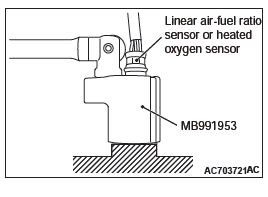
Required Special Tool:
- MB991953: Oxygen Sensor Wrench
REMOVAL SERVICE POINTS
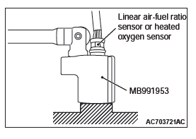
LINER AIR-FUEL RATIO SENSOR/HEATED OXYGEN SENSOR REMOVAL
Remove the connection and clamp of linear air-fuel ratio sensor connector or heated oxygen sensor connector, and then use special tool MB991953 to remove the linear air-fuel ratio sensor or heated oxygen sensor.
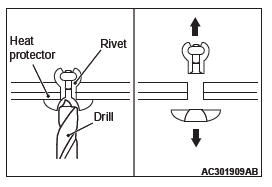
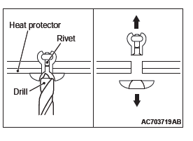
RIVET REMOVAL
CAUTION Be careful not to damage the heat protector with the drill.
Use a drill [6.0 mm (0.24 inch) ] to make a hole in the rivet to break it, and then remove the rivet.
INSTALLATION SERVICE POINTS
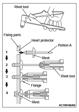
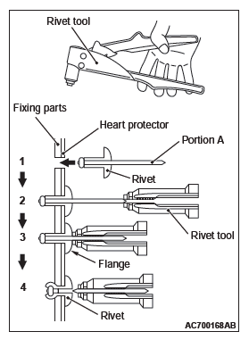
RIVET INSTALLATION
Use a rivet tool shown in the illustration to connect the parts with rivets by the following procedures.
1. Insert the rivet into a corresponding location.
2. Set the rivet tool at a portion A of rivet.
3. While pushing the flange surface of the rivet onto parts to be fixed with the rivet tool, press the handle of the tool.
4. Thin part of portion A of the rivet will be cut off and the part is fixed in position.
LINER AIR-FUEL RATIO SENSOR/HEATED OXYGEN SENSOR INSTALLATION
Tighten the linear air-fuel ratio sensor or heated oxygen sensor to the specified torque by using special tool MB991953.
Tightening torque: 44 +- 5 N*m (32 +- 3 ft-lb)
EXHAUST TAIL PIPE DIFFUSER INSTALLATION
When the part is reused, make sure that there is no excessive play after installation and that the part is securely fixed.
REMOVAL AND INSTALLATION <3.0L ENGINE>
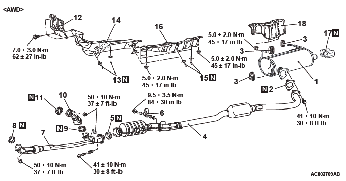
Exhaust main muffler and rear floor panel heat protector removal steps
- Exhaust main muffler
- Gasket
- Hanger
- Exhaust tail pipe diffuser
- Rear floor panel heat protector
Center exhaust pipe removal steps
- Center exhaust pipe
- Seal ring
- Gasket
- Hanger
Front exhaust pipe and front floor rear panel heat protector removal steps
- Front exhaust pipe
- Gasket
- Gasket
- Seal ring
- Front exhaust pipe RH
- Gasket
- Dash panel heat protector
- Rivet
- Front floor front panel heat protector
- Rivet
- Front floor rear panel heat protector
REMOVAL SERVICE POINTS
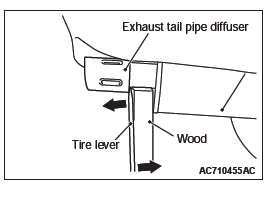
EXHAUST TAIL PIPE DIFFUSER REMOVAL
Insert the wood and tire lever between exhaust tail pipe diffuser and exhaust main muffler.
And then turn the tire lever and remove exhaust tail pipe diffuser.
RIVET REMOVAL
CAUTION Be careful not to damage the heat protector with the drill.
Use a drill [6.0 mm (0.24 inch) ] to make a hole in the rivet to break it, and then remove the rivet.
INSTALLATION SERVICE POINT
RIVET INSTALLATION
Use a rivet tool shown in the illustration to connect the parts with rivets by the following procedures.
1. Insert the rivet into a corresponding location.
2. Set the rivet tool at a portion A of rivet.
3. While pushing the flange surface of the rivet onto parts to be fixed with the rivet tool, press the handle of the tool.
4. Thin part of portion A of the rivet will be cut off and the part is fixed in position.
READ NEXT:
 Front Suspension
General Information
The MacPherson strut type suspension is adopted.
CONSTRUCTION DIAGRAM
Fastener Tightening Specifications
General Specifications
COIL SPRING
NOTE: * : Heavyduty suspension for F
Rear Suspension
General Information
A trailing arm type multi-link suspension is used. The
main features are listed as follows:
The wheel tread is enlarged to improve cornering
ability.
The roll center height is
SEE MORE:
Power Window Diagnosis
TROUBLESHOOTING STRATEGY
Refer to GROUP 00, How to Use Troubleshooting/Inspection
Service Points, Troubleshooting Contents.
DIAGNOSTIC TROUBLE CODE CHART POWER WINDOW
CAUTION
On troubleshooting, if the ignition switch is turned ON while disconnecting
connector(s), diagnostic
trouble code(s) associa
On-vehicle Service
A/T CONTROL COMPONENT LAYOUT
ESSENTIAL SERVICE
TRANSMISSION FLUID CHECK
1. Drive the vehicle until the transmission fluid temperature
rises to the normal operating temperature [70 − 80ºC (158 −
176ºF) ].
NOTE: The transmission fluid temperature is measured with
scan tool MB991958
