Mitsubishi Outlander: Front Suspension
General Information
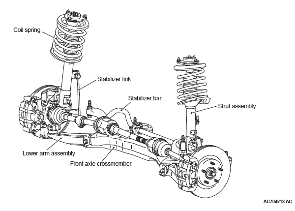
The MacPherson strut type suspension is adopted.
CONSTRUCTION DIAGRAM
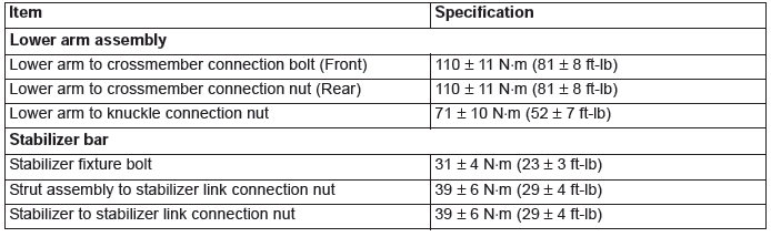
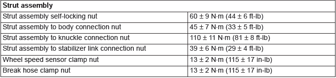
Fastener Tightening Specifications
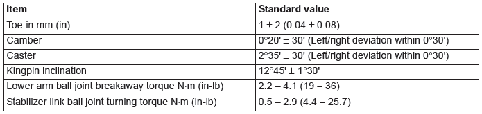
General Specifications
COIL SPRING
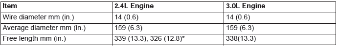
NOTE: * : Heavyduty suspension for FWD
Service Specifications
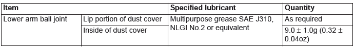
Lubricant
Front Suspension Diagnosis
INTRODUCTION TO FRONT SUSPENSION DIAGNOSIS
If the front suspension is faulty, the vehicle will not run straightforward or noise will occur. Incorrect wheel alignment, malfunction of strut assembly, stabilizer bar, coil spring, or worn or out-of-balance tires can cause these problems.
FRONT SUSPENSION DIAGNOSIS TROUBLESHOOTING STRATEGY
Use these steps to plan your diagnostic strategy. If you follow them carefully, you will be sure that you have exhausted most of the possible ways to find a front suspension fault.
1. Gather information from the customer.
2. Verify that the condition described by the customer exists.
3. Find and repair the malfunction by following the Symptom Chart and Symptom Procedures.
4. Verify malfunction is eliminated.
SYMPTOM CHART
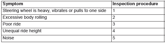
SYMPTOM PROCEDURES
INSPECTION PROCEDURE 1: Steering Wheel Is Heavy, Vibrates or Pulls to One Side
DIAGNOSIS
STEP 1. Check the tires.
Refer to GROUP 31, Diagnosis.
Q: Are the tires in normal condition?
YES : Replace the tires as necessary, then go to Step 2.
NO : If out of balance, balance the tires as necessary. If excessively worn, replace the tires as necessary and go to Step 5.
STEP 2. Check the wheel alignment.
Q: Is the wheel alignment correct?
YES : Go to Step 3.
NO : Adjust it, then go to Step 5.
STEP 3. Check the lower arm ball joint.
Q: Is the ball joint in good condition?
YES : Go to Step 4.
NO : Replace the lower arm assembly, then go to Step 5.
STEP 4. Check the coil spring.
Q: Is the coil spring in good condition?
YES : Go to Step 5.
NO : Replace it, then go to Step 5.
STEP 5. Retest the system.
Q: Is the malfunction eliminated?
YES : The procedure is complete.
NO : Return to Step 1.
INSPECTION PROCEDURE 2: Excessive Body Rolling
DIAGNOSIS
STEP 1. Check for broken or deteriorated stabilizer bar.
Q: Is the stabilizer bar in good condition?
YES : Go to Step 2.
NO : Replace it, then go to Step 3.
STEP 2. Check the strut assembly for damage.
Q: Is the strut assembly in good condition?
YES : Go to Step 3.
NO : Replace it, then go to Step 3.
STEP 3. Retest the system.
Q: Is the malfunction eliminated?
YES : The procedure is complete.
NO : Return to Step 1.
INSPECTION PROCEDURE 3: Poor Ride
DIAGNOSIS
STEP 1. Check for improper tire inflation pressure.
Refer to GROUP 31, On-vehicle Service − Tire Inflation Pressure Check.
Q: Is the tire inflation correct?
YES : Go to Step 2.
NO : Adjust it, then go to Step 4.
STEP 2. Check for broken or deteriorated coil spring(s).
Q: Are the coil spring(s) broken or deteriorated?
YES : Replace the coil spring(s), then go to Step 4.
NO : Go to Step 3.
STEP 3. Check for strut assembly damage.
Q: Is the strut assembly damaged?
YES : Replace it, then go to Step 4.
NO : Go to Step 4.
STEP 4. Retest the system.
Q: Is the malfunction eliminated?
YES : The procedure is complete.
NO : Return to Step 1.
INSPECTION PROCEDURE 4: Unequal Ride Height
DIAGNOSIS
STEP 1. Check for broken or deteriorated coil spring(s).
Q: Is the coil spring(s) broken or deteriorated?
YES : Replace it, then go to Step 2.
NO : Go to Step 2.
STEP 2. Retest the system.
Q: Is the malfunction eliminated?
YES : The procedure is complete.
NO : Return to Step 1.
INSPECTION PROCEDURE 5: Noise
DIAGNOSIS
STEP 1. Check for lack of lubrication.
Q: Is lubrication inadequate?
YES : Lubricate it, then go to Step 5.
NO : Go to Step 2.
STEP 2. Check the tightened parts for looseness as well as the bushings for wear.
Q: Are the tightened parts and bushings in good condition?
YES : Go to Step 3.
NO : Replace it, then go to Step 5.
STEP 3. Check for broken coil spring.
Q: Is the coil spring broken?
YES : Replace it, then go to Step 5.
NO : Go to Step 4.
STEP 4. Check for strut assembly damage.
Q: Is the strut assembly damaged?
YES : Replace it, then go to Step 5.
NO : Go to Step 5.
STEP 5. Retest the system.
Q: Is the malfunction eliminated?
YES : The procedure is complete.
NO : Return to Step 1.
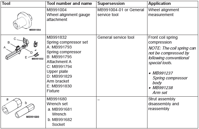
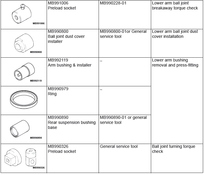
Special Tools
On-vehicle Service
FRONT WHEEL ALIGNMENT CHECK AND ADJUSTMENT
CAUTION After the installation, perform a calibration for the ASC-ECU to learn the steering wheel sensor neutral point.
(Refer to GROUP 35C − On-vehicle Service − Steering Wheel Sensor Calibration). <Vehicles with ASC>
Measure wheel alignment with alignment equipment on a level surface. The front suspension, steering system, wheels, and tires should be serviced to normal condition before measuring wheel alignment.
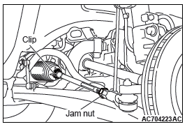
TOE-IN
Standard value: 1 +- 2 mm (0.04 +- 0.08 inch)
1. Adjust the toe-in by undoing the clip and jam nut, and turning the left and right tie rod turnbuckles by the same amount (in opposite directions).
NOTE: The toe will move out as the left turnbuckle is turned toward the front of the vehicle and the right turnbuckle is turned toward the rear of the vehicle.
2. Install the clip and tighten the jam nut to the specified torque.
Tightening torque: 52 +- 2 N*m (38 +- 1 ft-lb)
3. Confirm that the toe-in is at the standard value.
4. Use a turning radius gauge to check that the steering angle is at the standard value.
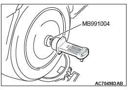
CAMBER, CASTER AND KINGPIN INCLINATION
Required Special Tool:
- MB991004: Wheel Alignment Gauge Attachment Vehicles with aluminum wheels
Standard value:
Camber 0º20' +- 0º30' (Left/right deviation within
0º30')
Caster 2º35' +- 0º30' (Left/right deviation within 0º30')
Kingpin inclination 12º45' +- 1º30'
NOTE: Camber and caster are preset at the factory and cannot be adjusted.
CAUTION Do not apply the vehicle weight to the wheel bearing while loosening the driveshaft nut.
NOTE: For vehicles with aluminum wheels, tighten special tool wheel alignment gauge attachment (MB991004) to the specified torque, then measure the camber.
Tightening torque: 144 - 176 N*m (106 - 130 ft-lb)
LOWER ARM BALL JOINT END PLAY CHECK
1. Raise the vehicle.
2. Remove the stabilizer link from the lower arm.
3. Move the lower arm up and down with your hands to check for an excessive play in the axial direction of the ball joint. If there is an excessive play, replace the lower arm assembly.
BALL JOINT DUST COVER CHECK
1. Using your fingers, press the dust cover to check for a crack or damage.
2. If the dust cover has a crack or damage, replace the lower arm assembly.
NOTE: If the dust cover has a crack or damage, the ball joint could be damaged.
Strut Assembly
REMOVAL AND INSTALLATION
CAUTION The part indicated by * is the nut with friction coefficient stabilizer. In removal, ensure there is no damage, clean dust and soiling from the bearing and thread surfaces, and tighten it to the specified torque.
Post-installation operation
- Front wheel alignment check and adjustment
- Headlight aiming adjustment
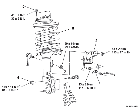
Removal steps
- Front wheel speed sensor clamp
- Brake hose bracket
- Stabilizer link and strut connection nut
- Knuckle and strut connection
- Strut mounting nut
- Strut assembly
REMOVAL SERVICE POINT
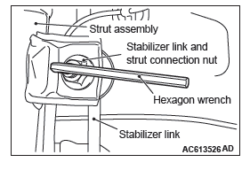
STABILIZER LINK AND STRUT CONNECTION NUT REMOVAL
Use a hexagon wrench to remove the stabilizer link and strut connection nut as shown in the figure.
INSTALLATION SERVICE POINT
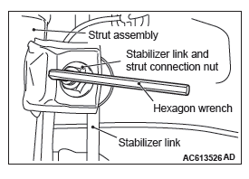
STABILIZER LINK AND STRUT CONNECTION NUT INSTALLATION
Use a hexagon wrench to install the stabilizer link and strut connection nut as shown in the figure.
INSPECTION
- Check for oil leaks from the strut assembly.
- Check the strut assembly for damage or deformation.
DISASSEMBLY AND ASSEMBLY
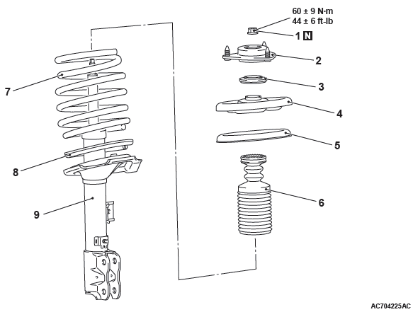
Disassembly steps
- Strut nut jam nut)
- Strut insulator assembly
- Strut bearing
- Upper spring seat
- Upper spring pad
- Bump rubber
- Coil spring
- Spring tube
- Strut
Required Special Tools:
- MB991681: Wrench
- MB991682: Socket
- MB991793: Spring compressor
- MB991794: Upper plate
- MB991795: Attachment A
- MB991830: Fixture
DISASSEMBLY SERVICE POINTS
STRUT NUT (JAM NUT) REMOVAL
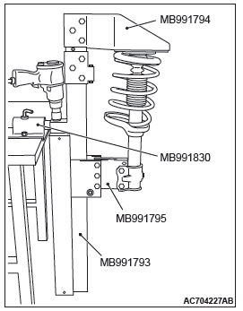
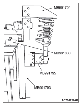
1. Install the special tool attachment A (MB991795) to the special tool spring compressor (MB991793) as shown in the figure.
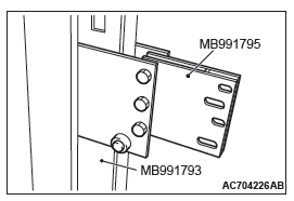
2. Set the strut assembly to the following special tools:
- Spring compressor (MB991793)
- Attachment A (MB991795)
- Upper plate (MB991794)
- Fixture (MB991830)
NOTE: Use the bolts and nuts removed from the vehicle to secure the strut assembly and tighten them lightly by hand.
3. After setting the strut assembly, operate the spring compressor and compress the coil spring by approximately 5 mm.
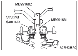
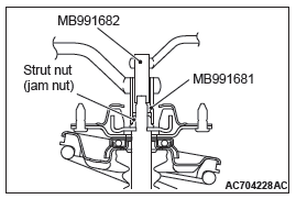
CAUTION The locking nut for the piston rod inside the strut may be loose. Do not use the impact wrench to loosen the strut nut (jam nut).
4. Use the following tools to loosen the strut nut (jum nut):
- Wrench (MB991681)
- Socket (MB991682)
STRUT REMOVAL
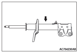
CAUTION Wear the protective glasses. Although the gas is harmless, drilling chips may be blown out by the gas.
Before disposal of the strut, place the strut on the level surface with the piston rod extended, and make a hole of approximately 3 mm in diameter at the point shown in the figure to discharge the gas.
ASSEMBLY SERVICE POINTS
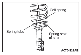
COIL SPRING INSTALLATION
1. Fit the coil spring to the spring tube securely.
2. Install the coil spring equipping with the spring tube to align the bottom with the shape of the strut spring sheet.
STRUT BEARING INSTALLATION
CAUTION Install the bearing without any damage.
STRUT NUT (JAM NUT) INSTALLATION
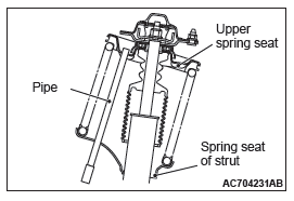
1. Check that both of the coil spring ends align with the spring sheet groove correctly.
2. Align the strut spring sheet hole with the upper spring sheet hole.
NOTE: Use the pipe to align the holes easily.
CAUTION Be careful that the hand is not pinched by the coil spring when aligning the piston rod with the hole of upper insulator while compressing the coil spring.
3. While passing the strut piston rod through the hole of upper insulator by hand, slowly compress the coil spring by the following special tool:
- Spring compressor (MB991793)
- Attachment A (MB991795)
- Upper plate (MB991794)
- Fixture (MB991830)
CAUTION The locking nut for the piston rod inside the strut may be loose. Do not use the impact wrench to loosen the strut nut (jam nut).
4. Use the following special tools to tighten the strut nut (jam nut) to the specified torque:
- Wrench (MB991681)
- Socket (MB991682)
Tightening torque: 60 +- 9 N*m (45 +- 6 ft-lb)
INSPECTION
- Check the bearing for wear or rust.
- Check the rubber parts for damage or deterioration.
- Check the spring for deformation, deterioration or damage.
- Check the shock absorber for deformation.
Lower Arm
REMOVAL AND INSTALLATION
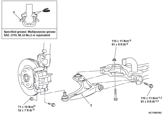
CAUTION
- The part indicated by *1 indicates parts which should be temporarily tightened, and then fully tightened with the vehicle standing on the ground and the curb weight condition.
- The parts indicated by *2 are the bolts/nuts with friction coefficient stabilizer. In removal, ensure there is no damage, clean dust and soiling from the bearing and thread surfaces, and tighten them to the specified torque.
Post-installation operation
- Using your fingers, press the dust cover to check for a crack or damage
- Wheel alignment check and adjustment
- Headlight aiming adjustment
Removal steps
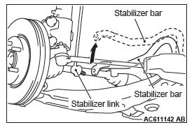
- Stabilizer link and stabilizer bar connection at both sides
- Lower arm assembly
REMOVAL SERVICE POINT
LOWER ARM ASSEMBLY REMOVAL
Rotate upward the stabilizer bar so as not to interfere the lower arm removal.
LOWER ARM CHECK
- Check the bushing for wear and deterioration.
- Check the lower arm for bend or breakage.
- Check all bolts for condition and straightness.
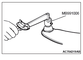
LOWER ARM BALL JOINT ROTATION STARTING TORQUE
1. Move the lower arm ball joint stud back and forth for several times, and measure the lower arm ball joint rotation starting torque using the special tool preload socket (MB991006).
Standard value: 2.2 − 4.1 N*m (19 − 36 in-lb)
2. If the measured value exceeds the standard range, replace the lower arm assembly.
3. Even if the measured value is within the standard range, check the lower arm ball joint that there is no looseness or gritty feeling. If there is no looseness or gritty feeling, it is judged as usable.
LOWER ARM BALL JOINT DUST COVER CHECK
1. Using your fingers, press the dust cover to check for a crack or damage.
2. If the dust cover has any crack or damage, replace the lower arm assembly.
NOTE: If the dust cover has a crack or damage, the ball joint could be damaged.
If the dust cover is damaged during the maintenance, replace it.
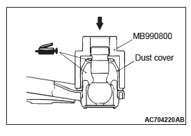
LOWER ARM BALL JOINT DUST COVER REPLACEMENT
Only when the dust cover is damaged accidentally during maintenance, replace the dust cover as follows:
1. Remove the dust cover.
2. Fill and apply the specified grease into the inside and lip of the dust cover.
Specified grease
Multipurpose grease SAE J310, NLGI No.2 or equivalent
Usage:
Inside of dust cover: 9.0 +- 1.0 g (0.32 +- 0.04 oz), Lip: As
required
3. Use the special tool ball joint remover & installer
(MB990800) to drive in the dust cover to the point where it
contact with the lower arm assembly.
4. Using your fingers, press the dust cover to check for a crack or damage.
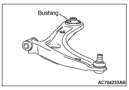
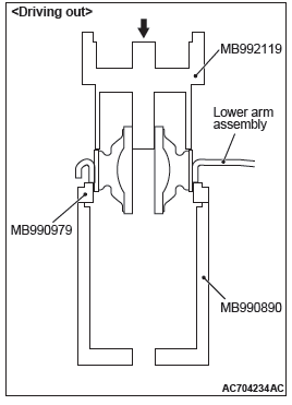
LOWER ARM BUSHING REPLACEMENT
Required Special Tools:
- MB992119: Arm bushing remover and installer
- MB990979: Ring
- MB990890: Rear suspension bushing base
Replace the back side bushing according to the following procedure.
1. Use the following special tools to remove the bushing:
- MB992119 (Arm bushing remover and installer)
- MB990979 (Ring)
- MB990890 (Rear suspension bushing base)
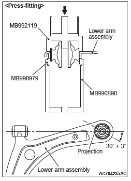
2. Use the following special tools to press-fit the bushing.
- MB992119 (Arm bushing remover and installer)
- MB990979 (Ring)
- MB990890 (Rear suspension bushing base)
3. Press-fit the bushing so that the bushing protrusion is in the direction shown in the figure.
4. Press-fit the bushing until the special tool contacts with the lower arm assembly.
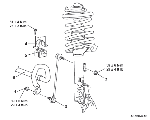
Stabilizer Bar
REMOVAL AND INSTALLATION
Post-installation operation
Front wheel alignment check and adjustment
Stabilizer link removal steps
- Stabilizer link and stabilizer bar connection nut
- Stabilizer link and strut connection nut
- Stabilizer link
Stabilizer bushing removal steps
- Stabilizer link and stabilizer bar connection nut
- Stabilizer bar bracket
- Stabilizer bushing
Stabilizer bar removal steps
- Stabilizer link and stabilizer bar connection nut
- Front axle crossmember
- Stabilizer bar bracket
- Stabilizer bushing
- Stabilizer bar
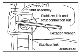
REMOVAL SERVICE POINT
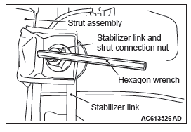
STABILIZER LINK AND STABILIZER BAR CONNECTION NUT/STABILIZER LINK AND STRUT CONNECTION NUT REMOVAL
Use a hexagon wrench to remove the stabilizer link and strut connection nut as shown in the figure.
INSTALLATION SERVICE POINTS
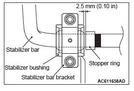
STABILIZER BAR INSTALLATION
Install the stabilizer bar as shown in the figure.
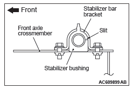
STABILIZER BUSHING INSTALLATION
Install the stabilizer bushing as shown in the figure.
STABILIZER LINK AND STRUT CONNECTION NUT/STABILIZER LINK AND STABILIZER BAR CONNECTION NUT INSTALLATION
Use a hexagon wrench to install the stabilizer link and strut connection nut as shown in the figure.
INSPECTION
- Check the bushings for wear and deterioration.
- Check the stabilizer bar for deterioration or damage.
- Check all bolts for condition and straightness.
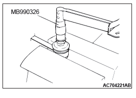
STABILIZER LINK BALL JOINT ROTATION STARTING TORQUE CHECK
1. Move the stabilizer link ball joint stud back and forth for several times, install the stud with nut, and measure the stabilizer link ball joint rotation starting torque using the special tool preload socket (MB990326).
Standard value: 0.5 − 2.9 N*m (4.4 − 26 in-lb)
2. When the measured value exceeds the standard range, replace the stabilizer link.
3. If the measured value stays within the standard range, and there is looseness or gritty feeling, the component is judged as unusable and should be replaced.
STABILIZER LINK BALL JOINT DUST COVER CHECK
1. Using your fingers, press the dust cover to check for a crack or damage.
2. If the dust cover has a crack or damage, replace the stabilizer link.
NOTE: If the dust cover has a crack or damage, the ball joint could be damaged.
READ NEXT:
 Rear Suspension
General Information
A trailing arm type multi-link suspension is used. The
main features are listed as follows:
The wheel tread is enlarged to improve cornering
ability.
The roll center height is
Rear Suspension Diagnosis
INTRODUCTION TO REAR SUSPENSION DIAGNOSIS
If the rear suspension is faulty, the vehicle will not run
straightforward or noise will occur. Incorrect wheel
alignment, malfunction of shock absorber, stab
Control Link, Upper Arm and Lower Arm
REMOVAL AND INSTALLATION
CAUTION
The parts indicated by *1 should be temporarily tightened, and then
fully tightened with the vehicle
standing on the ground and the curb weight condition.
The p
SEE MORE:
Air Bag Module(s) and Clock Spring
REMOVAL AND INSTALLATION
WARNING
Never attempt to disassemble or repair the air bag modules or
clock spring. If faulty,
replace it.
Do not drop the air bag modules or clock spring or allow contact
with water, grease or oil.
Replace it if a dent, crack, deformation or rust is detected.
The
Symptom Procedures
Inspection Procedure 1: None of headlights (low-beam) illuminates.
CAUTION
Whenever the ECU is replaced, ensure that the
power supply circuit, the ground circuit and the
communication circuit are normal.
Headlight Relay (Low-Beam) Circuit <Halogen Type>
Headlight Relay (Low-Beam) Circuit <
