Mitsubishi Outlander: DTC P0876, P0893, P0988, P1705, P1706, P1731, P1753, P1758, P1773, P1796, U0001, U0100, U0121, U0141
DTC P0876: High Clutch Pressure Switch System
DESCRIPTIONS OF MONITOR METHODS
- With the solenoid failure not detected and with 4th to 6th gear driving, the switch OFF status continues for 2 seconds. (The detection is achieved twice during 1 driving cycle*1, and it continues for 2 driving cycles.)
*1: Indicates the series of driving cycle "ignition key OFF → ON → drive → OFF". The "1 driving cycle", "2 driving cycle", and so on indicates how many cycles are required to detect a failure.
MONITOR EXECUTION
- 4th, 5th, and 6th gear driving
MONITOR EXECUTION CONDITIONS (OTHER MONITOR AND SENSOR)
Other Monitor (There is no temporary DTC stored in memory for the item monitored below)
- Not applicable
Sensor (The sensor below is determined to be normal)
- Not applicable
LOGIC FLOW CHARTS (Monitor Sequence)
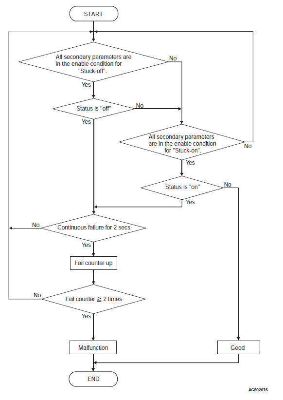
DTC SET CONDITIONS
Check Conditions <Stuck-off>
- Transmission range switch position: D
- Gear position: 4th, 5th, 6th
- Time after shift changing finish: 2 seconds or more
Judgment Criteria <Stuck-off>
- High clutch pressure switch status: OFF (2 seconds × 2times)
Check Conditions <Stuck-on>
- Transmission range switch position: D or R
- Gear position: 1st, 2nd, 3rd, reverse
- Time after shift changing finish: 2 seconds or more
Judgment Criteria <Stuck-on>
- High clutch pressure switch status: ON (2 seconds × 2times)
OBD-II DRIVE CYCLE PATTERN
Drive in 4th, 5th, and 6th gears for 2 seconds or more.
TROUBLESHOOTING HINTS (THE MOST LIKELY CAUSES FOR THIS CODE TO BE SET ARE:)
- Malfunction of the high clutch pressure switch system circuit
- Damaged harness or connector
- Malfunction of the TCM
- Malfunction of the high clutch pressure switch system (valve body assembly)
- Malfunction of the valve body assembly, abnormal hydraulic circuit valve.
CAUTION For the incomplete gear shifting and slippage, first refer to the SYMPTOM CHART.
DIAGNOSIS
STEP 1. Check the DTC.
Q: Is the DTC other than the pressure switch set? (Is the code other than P0846, P0876, and P0988 set?)
YES : Check and repair the relevant DTC system.
NO : Go to Step 2.
STEP 2. Check the TCM terminal voltage.
[C-37 TCM connector (vehicle side, connected) ]
Measure the voltage between C-37 terminal No. 45 and body ground.
- High clutch engaged: 0 V
- Other than above: Battery positive voltage
Q: Is the check result normal?
YES : Go to Step 3.
NO : Go to Step 7.
STEP 3. Check between the TCM connector and A/T control solenoid valve assembly.
Check for continuity between C-37 TCM connector and B-111 A/T control solenoid valve assembly connector.
NOTE: Prior to the wiring harness inspection, check the intermediate connectors A-12 and repair that if necessary.
- Between C-37 terminal No. 45 and B-111 terminal No. 5: Continuity exists.
When the continuity check result is OK, check that the wiring harness is not shorted to the body and other wiring harness.
Q: Is the check result normal?
YES : Go to Step 4.
NO : Repair or replace the failure section.
STEP 4. Check the TCM, A/T control solenoid valve assembly connector pin terminals, and the connection status.
Q: Is the check result normal?
YES : Go to Step 5.
NO : Repair or replace the failure section.
STEP 5. Check between the A/T control solenoid valve assembly connector and high clutch pressure switch.
Check for continuity between the B-111 A/T control solenoid valve assembly connector terminals and the high clutch pressure switch connector terminals.
- Between B-111 terminal No. 5 and high clutch pressure switch: Continuity exists.
When the continuity check result is OK, check that the wiring harness is not shorted to the body and other wiring harness.
Q: Is the check result normal?
YES : Go to Step 6.
NO : Repair or replace the failure section.
STEP 6. Check the high clutch pressure switch body ground.
Check for continuity between the high clutch pressure switch body and ground.
- Between the high clutch pressure switch body and body ground: Continuity exists.
Q: Is the check result normal?
YES : Replace the valve body assembly, and then go to Step 8.
NO : Repair or replace the failure section.
STEP 7. Check the TCM, A/T control solenoid valve assembly connector pin terminals, and the connection status.
Q: Is the check result normal?
YES : Go to Step 9.
NO : Repair or replace the failure section.
STEP 8. Erase the DTC code, and drive the vehicle for a while.
Check that the normal code is displayed.
Q: Is the check result normal?
YES : The procedure is complete.
NO : Replace the TCM.
STEP 9. Erase the DTC code, and drive the vehicle for a while.
Check that the normal code is displayed.
Q: Is the check result normal?
YES : The procedure is complete.
NO : Return to START.
DTC P0893: Interlock Detection
DESCRIPTIONS OF MONITOR METHODS
When sudden deceleration (2.5 m/s2) exceeding the setting time is detected with combination as follows; Stoplight switch: correct, output shaft speed sensor: correct, hydraulic switch: incorrect.
MONITOR EXECUTION
- Continuous
MONITOR EXECUTION CONDITIONS (OTHER MONITOR AND SENSOR)
Other Monitor (There is no temporary DTC stored in memory for the item monitored below)
- Not applicable
Sensor (The sensor below is determined to be normal)
- Not applicable
LOGIC FLOW CHARTS (Monitor Sequence)
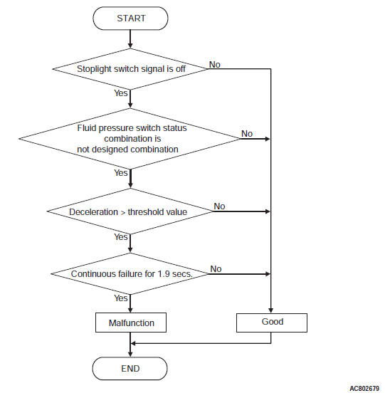
DTC SET CONDITIONS
Check Conditions
- Fluid pressure switch status combination: not designed combination
- Stoplight switch signal: OFF.
Judgement Criteria
- Deceleration: more than threshold value. (1.9 second)
OBD-II DRIVE CYCLE PATTERN
Start the engine, drive at 60 km/h (37.3 mph) or more for 15 minutes in total.
TROUBLESHOOTING HINTS (THE MOST LIKELY CAUSES FOR THIS CODE TO BE SET ARE:)
- Malfunction of the P0720: output shaft speed sensor system circuit
- Damaged harness or connector
- Malfunction of the P0743: lock-up and low-reverse brake linear solenoid valve system circuit
- Malfunction of the P0753: low clutch linear solenoid valve system circuit
- Malfunction of the P0758: 2-6 brake linear solenoid valve system circuit
- Malfunction of the P0763: 3-5 reverse clutch linear solenoid valve system circuit
- Malfunction of the P0768: high clutch linear solenoid valve system circuit
- Malfunction of the P1753: low clutch shift solenoid valve system circuit
- Malfunction of the P1758: low-reverse brake shift solenoid valve system circuit
- Malfunction of the P0846: 2-6 brake pressure switch system circuit
- Malfunction of the P0876: high clutch pressure switch system circuit
- Malfunction of the P0988: low-reverse brake pressure switch system circuit
DIAGNOSIS
STEP 1. Check the DTC.
Check if the following DTCs are set.
- P0720 output shaft speed sensor
- P0743 lock-up and low-reverse brake linear solenoid valve
- P0753 low clutch linear solenoid valve
- P0758 2-6 brake linear solenoid valve
- P0763 3-5 reverse clutch linear solenoid valve
- P0768 high clutch linear solenoid valve
- P1753 low clutch shift solenoid valve
- P1758 low-reverse brake shift solenoid valve
- P0846 2-6 brake pressure switch
- P0876 high clutch pressure switch
- P0988 low-reverse brake pressure switch
Q: Is the check result normal?
YES : Go to Step 2.
NO : Repair or replace the failure section.
STEP 2. Check TCM related to the solenoid, pressure switch and output shaft speed sensor, the A/T control solenoid valve assembly connector pin terminals, and the connection status.
Q: Is the check result normal?
YES : Replace the TCM, and then go to Step 3.
NO : Repair or replace the failure section.
STEP 3. Erase the DTC code, and drive the vehicle for a while.
Check that the normal code is displayed.
Q: Is the check result normal?
YES : The procedure is complete.
NO : Replace the transaxle assembly.
DTC P0988: Low-Reverse Brake Pressure Switch System
DESCRIPTIONS OF MONITOR METHODS
- During reverse driving, the switch OFF status continues for 2 seconds. (The detection is achieved twice during 1 driving cycle*1, and it continues for 2 driving cycles.)
*1: Indicates the series of driving cycle "ignition key OFF → ON → drive → OFF". The "1 driving cycle", "2 driving cycle", and so on indicates how many cycles are required to detect a failure.
MONITOR EXECUTION
- Reverse gear driving
MONITOR EXECUTION CONDITIONS (OTHER MONITOR AND SENSOR)
Other Monitor (There is no temporary DTC stored in memory for the item monitored below)
- Not applicable
Sensor (The sensor below is determined to be normal)
- Not applicable
LOGIC FLOW CHARTS (Monitor Sequence)
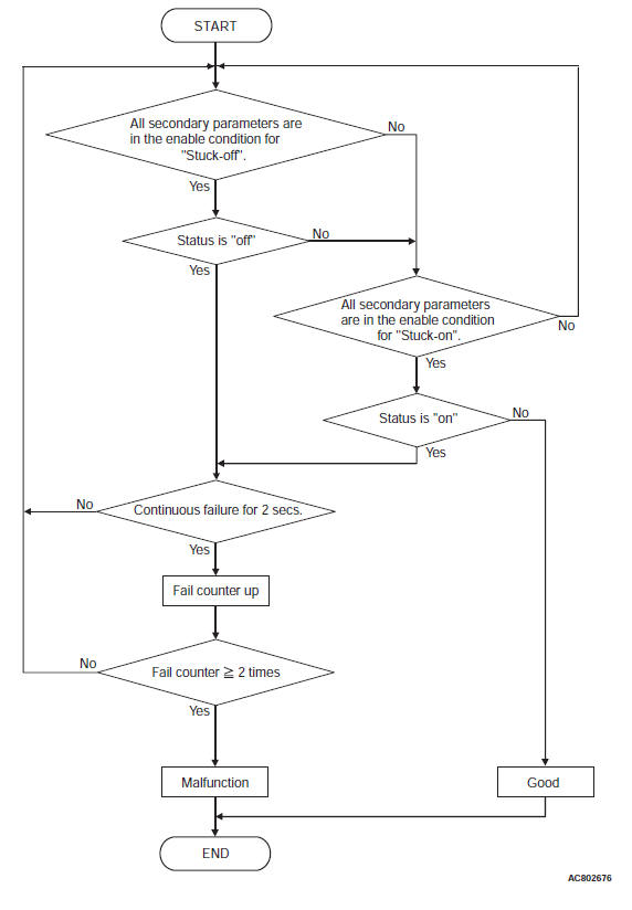
DTC SET CONDITIONS
Check Conditions <Stuck-off>
- Transmission range switch position: R
- Gear position: reverse
- Time after shift changing finish: 2 seconds or more
Judgment Criteria <Stuck-off>
- Low-reverse brake pressure switch status: OFF (2 seconds × 2times)
Check Conditions <Stuck-on>
- Transmission range switch position: D
- Gear position: 1st, 2nd, 3rd, 4th, 5th, 6th
- Time after shift changing finish: 2 seconds or more
Judgment Criteria <Stuck-on>
- Low-reverse brake pressure switch status: ON (2 seconds × 2times)
OBD-II DRIVE CYCLE PATTERN
Reverse gear driving for 2 seconds or more
TROUBLESHOOTING HINTS (THE MOST LIKELY CAUSES FOR THIS CODE TO BE SET ARE:)
- Malfunction of the low-reverse brake pressure switch system circuit
- Damaged harness or connector
- Malfunction of the TCM
- Malfunction of the low-reverse brake pressure switch system (valve body assembly)
- Malfunction of the valve body assembly, abnormal hydraulic circuit valve.
CAUTION For the incomplete gear shifting and slippage, first refer to the SYMPTOM CHART.
DIAGNOSIS
STEP 1. Check the DTC.
Q: Is the DTC other than the pressure switch set? (Is the code other than P0846, P0876, and P0988 set?)
YES : Check and repair the relevant DTC system.
NO : Go to Step 2.
STEP 2. Check the TCM terminal voltage.
[C-37 TCM connector (vehicle side, connected) ]
Measure the voltage between C-37 terminal No. 43 and body ground.
- Low-reverse brake engaged: 0 V
- Other than above: Battery positive voltage
Q: Is the check result normal?
YES : Go to Step 3.
NO : Go to Step 7.
STEP 3. Check between the TCM connector and A/T control solenoid valve assembly.
Check for continuity between C-37 TCM connector and B-111 A/T control solenoid valve assembly connector.
NOTE: Prior to the wiring harness inspection, check the intermediate connectors A-12 and repair that if necessary.
- Between C-37 terminal No. 43 and B-111 terminal No. 7: Continuity exists.
When the continuity check result is OK, check that the wiring harness is not shorted to the body and other wiring harness.
Q: Is the check result normal?
YES : Go to Step 4.
NO : Repair or replace the failure section.
STEP 4. Check the TCM, A/T control solenoid valve assembly connector pin terminals, and the connection status.
Q: Is the check result normal?
YES : Go to Step 5.
NO : Repair or replace the failure section.
STEP 5. Check between the A/T control solenoid valve assembly connector and low-reverse brake pressure switch.
Check for continuity between the B-111 A/T control solenoid valve assembly connector terminals and the low-reverse brake pressure switch connector terminals.
- Between B-111 terminal No. 7 and low-reverse brake pressure switch: Continuity exists.
When the continuity check result is OK, check that the wiring harness is not shorted to the body and other wiring harness.
Q: Is the check result normal?
YES : Go to Step 6.
NO : Repair or replace the failure section.
STEP 6. Check the low-reverse brake pressure switch body ground.
Check for continuity between the low-reverse brake pressure switch body and ground.
- Between the low-reverse brake pressure switch body and body ground: Continuity exists.
Q: Is the check result normal?
YES : Replace the valve body assembly, and then go to Step 8.
NO : Repair or replace the failure section.
STEP 7. Check the TCM, A/T control solenoid valve assembly connector pin terminals, and the connection status.
Q: Is the check result normal?
YES : Go to Step 9.
NO : Repair or replace the failure section.
STEP 8. Erase the DTC code, and drive the vehicle for a while.
Check that the normal code is displayed.
Q: Is the check result normal?
YES : The procedure is complete.
NO : Replace the TCM.
STEP 9. Erase the DTC code, and drive the vehicle for a while.
Check that the normal code is displayed.
Q: Is the check result normal?
YES : The procedure is complete.
NO : Return to START.
DTC P1705: Throttle Position Sensor Information (Engine)
DESCRIPTIONS OF MONITOR METHODS
With the vehicle speed 5 km/h (3.1 mph) or more or the output shaft speed sensor normal, and after the A/T-ECU startup, when approximately 1 second has elapsed, if the TPS fail signal is received for 5 seconds, or the APS fail signal is received for 3 seconds from the engine ECU.
MONITOR EXECUTION
- Vehicle speed 5 km/h (3.1 mph) or more
MONITOR EXECUTION CONDITIONS (OTHER MONITOR AND SENSOR)
Other Monitor (There is no temporary DTC stored in memory for the item monitored below)
- Not applicable
Sensor (The sensor below is determined to be normal)
- Not applicable
LOGIC FLOW CHARTS (Monitor Sequence)
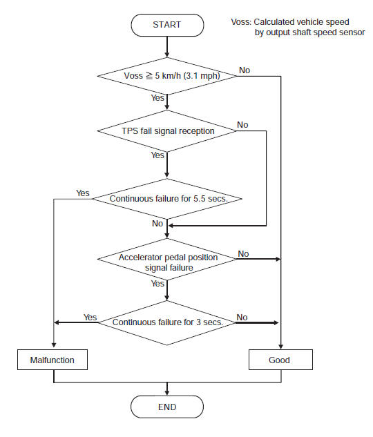
DTC SET CONDITIONS
Check Conditions <Throttle position sensor>
- TCM is started: more than 1.05 seconds.
- Vehicle speed: 5 km/h(3.1 mph) or more.
Judgement Criteria <Throttle position sensor>
- Throttle position sensor signal: fail. (5.5 seconds)
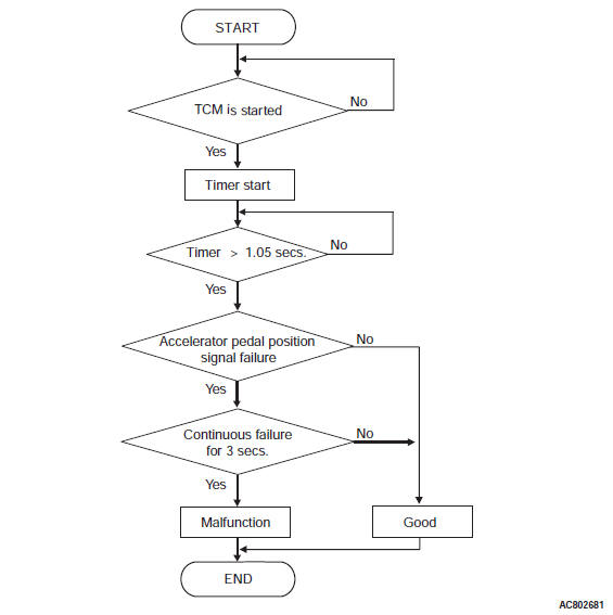
Check Conditions <Accelerator pedal position sensor>
- TCM is started: more than 1.05 seconds.
Judgement Criteria <Accelerator pedal position sensor>
- Accelerator pedal position sensor signal: fail. (3 seconds)
OBD-II DRIVE CYCLE PATTERN
Drive with the vehicle speed 5 km/h (3.1 mph) or more for 5 seconds or more.
TROUBLESHOOTING HINTS (THE MOST LIKELY CAUSES FOR THIS CODE TO BE SET ARE:)
- Malfunction of the CAN
- Malfunction of the ECM
- Damaged harness or connector
- Malfunction of the throttle position sensor
- Malfunction of the TCM
DIAGNOSIS
STEP 1. Check for CAN communication system malfunction.
Q: Are the DTC U0001, U0100, U0141, P1705, P1706 set?
YES : Check and repair the CAN communication system.
NO : Go to Step 2.
STEP 2. Check the throttle position sensor and ECM-side main unit and connector wiring.
Q: Is the check result normal?
YES : Go to Step 3.
NO : Repair or replace the failure section.
STEP 3. Erase the DTC code, and drive the vehicle for a while.
Check that the normal code is displayed.
Q: Is the check result normal?
YES : The procedure is complete.
NO : Replace the TCM.
DTC P1706: Accelerator Pedal Position Information
DESCRIPTIONS OF MONITOR METHODS
- When approx. 1 second has elapsed after TCM started, the throttle pedal position signal seizure is detected for 3 seconds.
MONITOR EXECUTION
- Continuous
MONITOR EXECUTION CONDITIONS (OTHER MONITOR AND SENSOR)
Other Monitor (There is no temporary DTC stored in memory for the item monitored below)
- P0712: Malfunction of the transmission fluid temperature sensor (Short circuit)
- P0715: Malfunction of the Input shaft speed sensor system
Sensor (The sensor below is determined to be normal)
- Transmission fluid temperature sensor
- Input shaft speed sensor
LOGIC FLOW CHARTS (Monitor Sequence)
DTC SET CONDITIONS
Check Conditions
- TCM is started: more than 1.05 seconds.
Judgement Criteria
- Accelerator pedal position sensor signal: fail. (3 seconds)
OBD-II DRIVE CYCLE PATTERN
With the ignition switch ON, maintain the status for 10 seconds or more.
TROUBLESHOOTING HINTS (THE MOST LIKELY CAUSES FOR THIS CODE TO BE SET ARE:)
- Malfunction of the CAN
- Malfunction of the ECM
- Damaged harness or connector
- Malfunction of the throttle position sensor
DIAGNOSIS
STEP 1. Is the DTC code for ECM displayed?
Check that the failure related to the engine does not occur.
Q: Is the check result normal?
YES : Go to Step 2.
NO : Repair or replace the failure section.
STEP 2. Check the throttle position sensor and ECM-side main unit and connector wiring.
Q: Is the check result normal?
YES : Go to Step 3.
NO : Repair or replace the failure section.
STEP 3. Erase the DTC code, and drive the vehicle for a while.
Check that the normal code is displayed.
Q: Is the check result normal?
YES : The procedure is complete.
NO : Return to START.
DTC P1731: 1st Engine Brake Detection
DESCRIPTIONS OF MONITOR METHODS
- With the mode other than SPORT MODE and with the accelerator angle is smaller than 6/8, the correlation between the lock-up and low-reverse brake linear solenoid valve control current and the low-reverse brake pressure switch ON/OFF is abnormal.
TROUBLESHOOTING HINTS (THE MOST LIKELY CAUSES FOR THIS CODE TO BE SET ARE:)
- Transaxle assembly powertrain parts failure
- Malfunction of the valve assembly (Malfunction of hydraulic valve and hydraulic switch)
- Malfunction of the TCM
- Malfunction of the lock-up and low-reverse brake linear solenoid valve (valve assembly)
- Malfunction of the low-reverse brake pressure switch (valve assembly)
- Malfunction of the low clutch pressure switch (valve assembly)
- Malfunction of the low clutch linear solenoid valve (valve assembly)
- Malfunction of the low-reverse brake shift solenoid valve (valve assembly)
- Malfunction of the low clutch, low-reverse brake
DIAGNOSIS
STEP 1. Check the DTC.
Check that P0988 (Low-reverse brake pressure switch) is set.
Q: Is the DTC set? YES : Check and repair the relevant DTC system.
NO : Go to Step 2.
STEP 2. Check the DTC.
Check that the DTC other than P1731 (1st engine brake detection) is set.
Q: Is the DTC set?
YES : Check and repair the relevant DTC system.
NO : Go to Step 3.
STEP 3. Check the transmission fluid properties.
Check the status of the transmission fluid properties (smell, color, fouling).
- Black: A/T inside damage, seizure
- Milky: Water intrusion
Q: Is the check result normal?
YES : Go to Step 4.
NO : Remove the A/T from the vehicle, then check and repair the inside.
STEP 4. Check the transmission fluid level.
Q: Is the check result normal?
YES : Go to Step 5.
NO : Adjust the transmission fluid level, and then go to Step 5.
STEP 5. Check the wiring harness, connector, and sensor signal.
- Check the wiring harness and connectors of the low-clutch pressure switch and low-reverse brake pressure switch.
- Check the signals of C-37 TCM connector terminal No. 37 (output shaft speed sensor) and the terminal No. 38 (input shaft speed sensor).
Q: Is the check result normal?
YES : Go to Step 6.
NO : Repair or replace the failure section.
STEP 6. Hydraulic pressure test
Q: Is the check result normal?
YES : Go to Step 7.
NO : Remove the A/T from the vehicle, then check and repair the inside.
STEP 7. Erase the DTC code, and drive the vehicle for a while.
Check that the normal code is displayed.
Q: Is the check result normal?
YES : The procedure is complete.
NO : Return to START.
DTC P1753: Low Clutch Shift Solenoid Valve System
DESCRIPTIONS OF MONITOR METHODS
- During 1st to 4th driving, and with the lock-up function deactivated, an open circuit is detected for 200 milliseconds.
- During the 5th to 6th driving, and with the lock-up function deactivated, a short circuit is detected for 200 milliseconds.
MONITOR EXECUTION
- During with the lock-up deactivated
MONITOR EXECUTION CONDITIONS (OTHER MONITOR AND SENSOR)
Other Monitor (There is no temporary DTC stored in memory for the item monitored below)
- P0731: Malfunction of the 1st gear incorrect ratio
- P0732: Malfunction of the 2nd gear incorrect ratio
- P0733: Malfunction of the 3rd gear incorrect ratio
- P0734: Malfunction of the 4th gear incorrect ratio
- P0735: Malfunction of the 5th gear incorrect ratio
- P0729: Malfunction of the 6th gear incorrect ratio
Sensor (The sensor below is determined to be normal)
- Not applicable
LOGIC FLOW CHARTS (Monitor Sequence)
DTC SET CONDITIONS
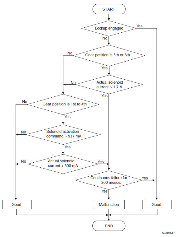
Check Conditions <Circuit continuity ground>
- Lock-up status: engaged.
- Gear position: 5th or 6th.
Judgment Criteria <Circuit continuity ground>
- Low clutch shift solenoid valve actual current: more than 1.7 A
Check Conditions <Circuit continuity open>
- Lock-up status: engaged.
- Gear position: 1st to 4th.
- Low clutch shift solenoid valve activation command: more than 937 mA
Judgment Criteria <Circuit continuity open>
- Low clutch shift solenoid valve actual current: less than 500 mA. (0.2 seconds)
OBD-II DRIVE CYCLE PATTERN
Drive at 55 km/h (34.2 mph) or less with the shift ranges of 1st, 2nd, 3rd, and 4th gear. Driving at 48 +- 2 km/h (29.8 +- 1.2 mph) with the 5th gear. Maintain each shift range for 1 second or more.
TROUBLESHOOTING HINTS (THE MOST LIKELY CAUSES FOR THIS CODE TO BE SET ARE:)
- Malfunction of the low clutch shift solenoid valve system circuit
- Damaged harness or connector
- Malfunction of the TCM
- Malfunction of the low clutch shift solenoid valve (valve body Assembly)
DIAGNOSIS
STEP 1. Check the TCM terminal voltage.
[C-38 TCM connector (vehicle side, connected) ]
Measure the voltage between terminal No. 14 and body ground.
- 5th and 6th: Battery positive voltage
- Other than above: 0 V
Q: Is the check result normal?
YES : Go to Step 5.
NO : Go to Step 2.
STEP 2. Check between the TCM connector and A/T control solenoid valve assembly connector.
Check for continuity between C-38 TCM connector and B-111 A/T control solenoid valve assembly connector.
NOTE: Prior to the wiring harness inspection, check the intermediate connectors A-12 and repair that if necessary.
- Between C-38 terminal No. 14 and B-111 terminal No. 22: Continuity exists.
When the continuity check result is OK, check that the wiring harness is not shorted to the body and other wiring harness.
Q: Is the check result normal?
YES : Go to Step 3.
NO : Repair or replace the failure section.
STEP 3. Check the low clutch shift solenoid.
Q: Is the check result normal?
YES : Go to Step 6.
NO : Go to Step 4.
STEP 4. Check between the A/T control solenoid valve assembly connector and the low clutch shift solenoid valve connector.
Check for continuity between the B-111 A/T control solenoid valve assembly connector terminals and the low clutch shift solenoid valve connector terminals.
- Between B-111 terminal No. 22 and low clutch shift solenoid valve: Continuity exists.
Q: Is the check result satisfactory?
YES : Replace the valve body assembly.
NO : Repair or replace the failure section.
STEP 5. Check the TCM and A/T control solenoid valve assembly connector pin terminals and the connection status.
Q: Is the check result normal?
YES : Go to Step 7.
NO : Repair or replace the failure section.
STEP 6. Check the TCM and A/T control solenoid valve assembly connector pin terminals and the connection status.
Q: Is the check result normal?
YES : Replace the TCM.
NO : Repair or replace the failure section.
STEP 7. Erase the DTC code, and drive the vehicle for a while.
Check that the normal code is displayed.
Q: Is the check result normal?
YES : The procedure is complete.
NO : Return to START.
DTC P1758: Low-Reverse Brake Shift Solenoid Valve System
DESCRIPTIONS OF MONITOR METHODS
- With the ignition switch ON, the open or short circuit is detected for 200 milliseconds.
MONITOR EXECUTION
- Continuous
MONITOR EXECUTION CONDITIONS (OTHER MONITOR AND SENSOR)
Other Monitor (There is no temporary DTC stored in memory for the item monitored below)
- P0731: Malfunction of the 1st gear incorrect ratio
- P0732: Malfunction of the 2nd gear incorrect ratio
- P0733: Malfunction of the 3rd gear incorrect ratio
- P0734: Malfunction of the 4th gear incorrect ratio
- P0735: Malfunction of the 5th gear incorrect ratio
- P0729: Malfunction of the 6th gear incorrect ratio
Sensor (The sensor below is determined to be normal)
- Not applicable
LOGIC FLOW CHARTS (Monitor Sequence)
DTC SET CONDITIONS
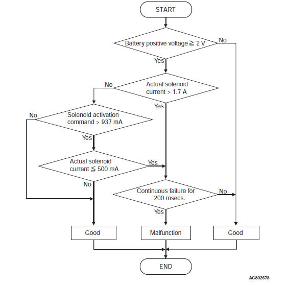
Check Conditions <Circuit continuity ground>
- Voltage of battery: 2 volts or more.
Judgment Criteria <Circuit continuity ground>
- Low-reverse brake shift solenoid valve actual current: more than 1.7 A (0.2 second)
Check Conditions <Circuit continuity open>
- Voltage of battery: 2 volts or more.
- Low-reverse brake shift solenoid valve activation command: more than 937 mA
Judgment Criteria <Circuit continuity open>
- Low-reverse brake shift solenoid valve actual current: less than 500 mA. (0.2 seconds)
OBD-II DRIVE CYCLE PATTERN
With the ignition switch ON, maintain the status for 10 seconds or more.
TROUBLESHOOTING HINTS (THE MOST LIKELY CAUSES FOR THIS CODE TO BE SET ARE:)
- Malfunction of the low-reverse brake shift solenoid valve system circuit
- Damaged harness or connector
- Malfunction of the TCM
- Malfunction of the low-reverse brake shift solenoid valve (valve body assembly)
DIAGNOSIS
STEP 1. Check the TCM terminal voltage.
[C-37 TCM connector (vehicle side, connected) ]
Measure the voltage between the terminal No. 51 and body ground.
- Reverse and 1st coast: Battery positive voltage
- Other than above: 0 V
Q: Is the check result normal?
YES : Go to Step 5.
NO : Go to Step 2.
STEP 2. Check between the TCM connector and A/T control solenoid valve assembly connector.
Check for continuity between C-37 TCM connector and B-111 A/T control solenoid valve assembly connector.
NOTE: Prior to the wiring harness inspection, check the intermediate connectors A-12 and repair that if necessary.
- Between C-37 terminal No. 51 and B-111 terminal No. 17: Continuity exists.
When the continuity check result is OK, check that the wiring harness is not shorted to the body and other wiring harness.
Q: Is the check result normal?
YES : Go to Step 3.
NO : Repair or replace the failure section.
STEP 3. Check the low-reverse brake shift solenoid.
Q: Is the check result normal?
YES : Go to Step 6.
NO : Go to Step 4.
STEP 4. Check between the A/T control solenoid valve assembly connector and the low-reverse brake shift solenoid valve connector.
Check for continuity between the B-111 A/T control solenoid valve assembly connector terminals and the low-reverse brake shift solenoid valve connector terminals.
- Between B-111 terminal No. 17 and low-reverse brake shift solenoid valve: Continuity exists.
Q: Is the check result satisfactory? YES : Replace the valve body assembly.
NO : Repair or replace the failure section.
STEP 5. Check the TCM and A/T control solenoid valve assembly connector pin terminals and the connection status.
Q: Is the check result normal?
YES : Go to Step 7.
NO : Repair or replace the failure section.
STEP 6. Check the TCM and A/T control solenoid valve assembly connector pin terminals and the connection status.
Q: Is the check result normal?
YES : Replace the TCM.
NO : Repair or replace the failure section.
STEP 7. Erase the DTC code, and drive the vehicle for a while.
Check that the normal code is displayed.
Q: Is the check result normal?
YES : The procedure is complete.
NO : Return to START.
DTC P1773: ABS Information (ABS/ASC)
DESCRIPTIONS OF MONITOR METHODS
- When approx. 1 second has elapsed after TCM started, the ABS/ASC abnormality signal is received via the CAN communication with vehicle speed at 55 km/h (34.4 mph) or more.
MONITOR EXECUTION
- Vehicle speed 55 km/h (34.4 mph) or more
MONITOR EXECUTION CONDITIONS (OTHER MONITOR AND SENSOR)
Other Monitor (There is no temporary DTC stored in memory for the item monitored below)
- Not applicable
Sensor (The sensor below is determined to be normal)
- Not applicable
LOGIC FLOW CHARTS (Monitor Sequence)
DTC SET CONDITIONS
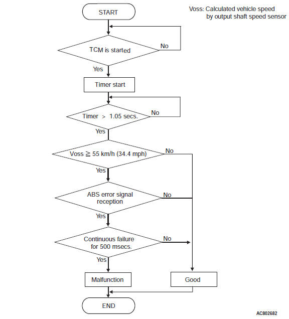
Check Conditions
- TCM is started: more than 1.05 seconds.
- Vehicle speed: more than 55 km/h (34.4 mph).
Judgement Criteria
- ABS status signal: fail. (0.5 second)
OBD-II DRIVE CYCLE PATTERN
Drive with the vehicle speed 5 km/h or more for 5 seconds or more.
TROUBLESHOOTING HINTS (THE MOST LIKELY CAUSES FOR THIS CODE TO BE SET ARE:)
- Malfunction of the CAN
- Malfunction of the ABS/ASC-ECU
DIAGNOSIS
STEP 1. Check the ABS/ASC-ECU.
Check if a failure related to ABS/ASC-ECU occurs.
Q: Is the check result satisfactory? YES : Go to Step 2.
NO : Repair or replace the failure section.
STEP 2. Check the ABS/ASC-ECU connector pin terminal and the connection status.
Q: Is the check result normal?
YES : Go to Step 3.
NO : Repair or replace the failure section.
STEP 3. Erase the DTC code, and drive the vehicle for a while.
Check that the normal code is displayed.
Q: Is the check result normal?
YES : The procedure is complete.
NO : Return to START.
Code No. P1796: Idle neutral control malfunction
DIAGNOSTIC TROUBLE CODE SET CONDITIONS
- With the idle neutral control, the status that the "actual slip speed − target slip speed" is faster than 300 r/min continues for 10 seconds.
- 1.05 seconds after the TCM activation, the failure signal of longitudinal G-sensor is received.
PROBABLE CAUSES
- Malfunction of the CAN circuit
- Malfunction of the P0753: low clutch linear solenoid valve system
- Malfunction of the P0731: 1st gear incorrect ratio
- Malfunction of the TCM
DIAGNOSTIC PROCEDURE
STEP 1. M.U.T.-III CAN bus diagnostics.
Use scan tool to perform the CAN bus diagnosis.
Q: Is the check result normal?
YES : Go to Step 2.
NO : Repair the CAN bus line.
STEP 2. Check the diagnostic trouble code.
Check the ASC diagnostic trouble code.
Q: Is the diagnostic trouble code set?
YES : Check and repair the relevant diagnostic trouble code system.
NO : Go to Step 3.
STEP 3. Perform the troubleshooting for diagnostic trouble code No. P0753: low clutch linear solenoid valve and diagnostic trouble code No. P0731: 1st gear incorrect ratio.
Check whether the diagnostic trouble code is reset.
Q: Is diagnostic trouble code No.P1796 set?
YES : Replace the TCM.
NO : This diagnosis is complete.
DTC U0001: Can Bus Off
DESCRIPTIONS OF MONITOR METHODS
- Open circuit or short circuit occurs in the CAN communication line (CAN_H, CAN_L).
- The communication becomes impossible with all the control modules for 0.5 seconds or more.
MONITOR EXECUTION
- Continuous
MONITOR EXECUTION CONDITIONS (OTHER MONITOR AND SENSOR)
Other Monitor (There is no temporary DTC stored in memory for the item monitored below)
- P0712: Malfunction of the transmission fluid temperature sensor (Short circuit)
- P0715: Malfunction of the Input shaft speed sensor system
- P0731: Malfunction of the 1st gear incorrect ratio
- P0732: Malfunction of the 2nd gear incorrect ratio
- P0733: Malfunction of the 3rd gear incorrect ratio
- P0734: Malfunction of the 4th gear incorrect ratio
- P0735: Malfunction of the 5th gear incorrect ratio
- P0729: Malfunction of the 6th gear incorrect ratio
- P0741: Malfunction of the Malfunction of the Torque converter clutch system (Stuck off)
- P0742: Malfunction of the Torque converter clutch system (Stuck on)
- P0846: Malfunction of the 2-6 brake pressure switch system
- P0876: Malfunction of the High clutch pressure switch system
- P0988: Malfunction of the Low-reverse brake pressure switch system
- P0893: Malfunction of the Interlock detection
- P1705: Malfunction of the Throttle position sensor information (engine)
- P1706: Malfunction of the Accelerator pedal position information
- P1773: Malfunction of the ABS information (ASC)
- U0100: Malfunction of the ECM time-out
Sensor (The sensor below is determined to be normal)
- Transmission fluid temperature sensor
- Input shaft speed sensor
LOGIC FLOW CHARTS (Monitor Sequence)
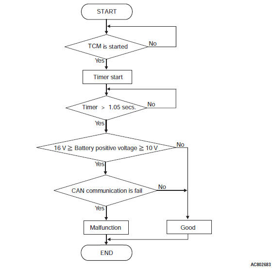
DTC SET CONDITIONS
Check Conditions
- TCM is started: more than 1.05 seconds.
- A/T control relay voltage: 10 volts or more.
- A/T control relay voltage: 16 volts or less.
Judgement Criteria
- CAN communication: fail.
OBD-II DRIVE CYCLE PATTERN
- With the ignition switch ON, maintain the status for 10 seconds or more.
TROUBLESHOOTING HINTS (THE MOST LIKELY CAUSES FOR THIS CODE TO BE SET ARE:)
- Malfunction of the CAN circuit
- Malfunction of the TCM
- Damaged harness or connector
- Malfunction of the CAN system module
DIAGNOSIS
STEP 1. Check the CAN communication system malfunction.
- Check that the CAN system-related DTC code other than U0001 is set.
- Check that the CAN-related DTC is set with other relevant modules.
Q: Is the check result normal?
YES : Go to Step 2.
NO : Repair or replace the failure section.
STEP 2. Check the CAN communication lines.
[C-38 TCM connector (vehicle side, disconnected) ]
Between C-38 terminal No. 10, 11 and the CAN communication lines of other ECU: Continuity exists.
When the continuity check result is OK, check that the wiring harness is not shorted to the body and other wiring harness.
Also, check for a short circuit between the twisted pair cables.
Q: Is the check result normal?
YES : Go to Step 3.
NO : Repair or replace the failure section.
STEP 3. Check the relevant ECUs and the TCM connector pin terminal, and the connection status.
Q: Is the check result normal?
YES : Repair or replace the failure section.
NO : Replace the TCM.
DTC U0100: ECM Time-out
DESCRIPTIONS OF MONITOR METHODS
- Open circuit or short circuit occurs in the CAN communication line (CAN_H, CAN_L).
- Reception from ECM becomes impossible for 0.5 seconds or more.
MONITOR EXECUTION
- Continuous
MONITOR EXECUTION CONDITIONS (OTHER MONITOR AND SENSOR)
Other Monitor (There is no temporary DTC stored in memory for the item monitored below)
- P0712: Malfunction of the transmission fluid temperature sensor (Short circuit)
- P0715: Malfunction of the Input shaft speed sensor system
- P0731: Malfunction of the 1st gear incorrect ratio
- P0732: Malfunction of the 2nd gear incorrect ratio
- P0733: Malfunction of the 3rd gear incorrect ratio
- P0734: Malfunction of the 4th gear incorrect ratio
- P0735: Malfunction of the 5th gear incorrect ratio
- P0729: Malfunction of the 6th gear incorrect ratio
- P0741: Malfunction of the Malfunction of the Torque converter clutch system (Stuck off)
- P0742: Malfunction of the Torque converter clutch system (Stuck on)
- P0846: Malfunction of the 2-6 brake pressure switch system
- P0876: Malfunction of the High clutch pressure switch system
- P0988: Malfunction of the Low-reverse brake pressure switch system
- P1705: Malfunction of the Throttle position sensor information (engine)
- P1706: Malfunction of the Accelerator pedal position information
Sensor (The sensor below is determined to be normal)
- Transmission fluid temperature sensor
- Input shaft speed sensor
LOGIC FLOW CHARTS (Monitor Sequence)
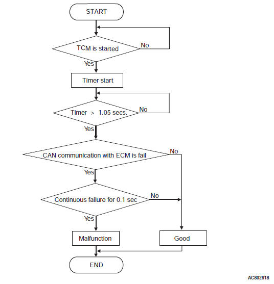
DTC SET CONDITIONS
Check Conditions
- TCM is started: more than 1.05 seconds.
Judgement Criteria
- CAN communication with ECM: fail.
OBD-II DRIVE CYCLE PATTERN
With the ignition switch ON, maintain the status for 10 seconds or more.
TROUBLESHOOTING HINTS (THE MOST LIKELY CAUSES FOR THIS CODE TO BE SET ARE:)
- Damaged harness or connector
- Malfunction of the CAN communication
- Malfunction of the ECM
- Malfunction of the TCM
DIAGNOSIS
STEP 1. Check the CAN communication system malfunction.
- Check that the CAN system-related DTC code other than U0100 is set.
- Check if the CAN-related DTC is set with ECM.
- Check if the failure related to the engine occurs.
Q: Is the check result normal?
YES : Go to Step 2.
NO : Repair or replace the failure section.
STEP 2. Check the CAN communication lines.
[C-38 TCM connector (vehicle side, disconnected) ]
Between C-38 terminal No. 10, 11 and the CAN communication lines of ECM: Continuity exists.
When the continuity check result is OK, check that the wiring harness is not shorted to the body and other wiring harness.
Also, check for a short circuit between the twisted pair cables.
Q: Is the check result normal?
YES : Go to Step 3.
NO : Repair or replace the failure section.
STEP 3. Check ECM, the TCM connector pin terminal, and the connection status.
Q: Is the check result normal?
YES : Repair or replace the failure section.
NO : Replace the TCM.
DTC U0121: ABS/ASC-ECU Time Out
DESCRIPTIONS OF MONITOR METHODS
- Open circuit or short circuit occurs in the CAN communication line (CAN_H, CAN_L).
- Reception from ABS/ASC-ECU becomes impossible for 0.5 seconds or more.
TROUBLESHOOTING HINTS (THE MOST LIKELY CAUSES FOR THIS CODE TO BE SET ARE:)
- Damaged harness or connector
- Malfunction of the CAN communication
- Malfunction of the ABS/ASC-ECU
- Malfunction of the TCM
DIAGNOSIS
STEP 1. Check the CAN communication system malfunction.
- Check that the CAN system-related DTC code other than U0121 is set.
- Check if the CAN-related DTC is set with ABS/ASC-ECU.
- Check if the failure related to the ABS/ASC occurs.
Q: Is the check result normal?
YES : Go to Step 2.
NO : Repair or replace the failure section.
STEP 2. Check the CAN communication lines.
[C-38 TCM connector (vehicle side, disconnected) ]
Between C-38 terminal No. 10, 11 and the CAN communication lines of ABS/ASC-ECU: Continuity exists.
When the continuity check result is OK, check that the wiring harness is not shorted to the body and other wiring harness.
Also, check for a short circuit between the twisted pair cables.
Q: Is the check result normal?
YES : Go to Step 3.
NO : Repair or replace the failure section.
STEP 3. Check the ABS/ASC-ECU, the TCM connector pin terminal, and the connection status.
Q: Is the check result normal?
YES : Repair or replace the failure section.
NO : Replace the TCM.
DTC U0141: ETACS-ECU Time Out
DESCRIPTIONS OF MONITOR METHODS
- Open circuit or short circuit occurs in the CAN communication line (CAN_H, CAN_L).
- Reception from ETACS-ECU becomes impossible for 0.5 seconds or more.
TROUBLESHOOTING HINTS (THE MOST LIKELY CAUSES FOR THIS CODE TO BE SET ARE:)
- Damaged harness or connector
- Malfunction of the CAN communication
- Malfunction of the ETACS-ECU
- Malfunction of the TCM
DIAGNOSIS
STEP 1. Check the CAN communication system malfunction.
- Check that the CAN system-related DTC code other than U0141 is set.
- Check if the CAN-related DTC is set with ETACS-ECU.
- Check if the failure related to the ETACS occurs.
Q: Is the check result normal?
YES : Go to Step 2.
NO : Repair or replace the failure section.
STEP 2. Check the CAN communication lines.
[C-38 TCM connector (vehicle side, disconnected) ]
Between C-38 terminal No. 10, 11 and the CAN communication lines of ETACS-ECU: Continuity exists.
When the continuity check result is OK, check that the wiring harness is not shorted to the body and other wiring harness.
Also, check for a short circuit between the twisted pair cables.
Q: Is the check result normal?
YES : Go to Step 3.
NO : Repair or replace the failure section.
STEP 3. Check the ETACS-ECU, the TCM connector pin terminal, and the connection status.
Q: Is the check result normal?
YES : Repair or replace the failure section.
NO : Replace the TCM.
READ NEXT:
 Inspection Procedure
INSPECTION PROCEDURE 1: The vehicle does not run at any range
(including low power).
TROUBLESHOOTING HINTS (THE MOST
LIKELY CAUSES FOR THIS CONDITION:)
Malfunction of the engine
Insufficient trans
Diagnosis S-AWC (Super All Wheel Control)
TROUBLESHOOTING STRATEGY
Refer to GROUP 00 − How to Use Troubleshooting/
Inspection Service Points.
PRECAUTIONS FOR DIAGNOSIS
Before diagnosis, check that all the following items
are normal.
DTC No.C100A, C1015, C1020, C102B, C1011, C101C, C1027, C1032,
C1014, C101F, C102A, C1035, C1078, C1219, C121A, C123C, C1242, C145F, C1460,
C1610, C1614, C1616
Code No.C100A <FL>, C1015 <FR>, C1020 <RL>, C102B <RR>: Wheel Speed
Sensor System (Faulty
Circuit)
CAUTION
If there is any problem in the CAN bus lines,
an incorrect diagno
SEE MORE:
Power Steering Diagnosis
INTRODUCTION TO POWER STEERING DIAGNOSIS
Hydraulic power steering is used for all vehicles.
Faults in the power steering can include excessive
play of the steering wheel, difficult steering wheel
operation, noise, vibration, and oil leaks, etc. Possible
causes of these faults can include defects in
Troubleshooting Strategy, Diagnostic Function
TROUBLESHOOTING STRATEGY
NOTE: If a DTC is erased, its "freeze frame" data will
also be erased and system readiness test status will
be reset. Store the "freeze frame" data before erasing
the DTC.
Use these steps to plan your diagnostic strategy. If
you follow them carefully, you will be sure to hav
