Mitsubishi Outlander: DTC No.C100A, C1015, C1020, C102B, C1011, C101C, C1027, C1032, C1014, C101F, C102A, C1035, C1078, C1219, C121A, C123C, C1242, C145F, C1460, C1610, C1614, C1616
Code No.C100A <FL>, C1015 <FR>, C1020 <RL>, C102B <RR>: Wheel Speed Sensor System (Faulty Circuit)
CAUTION
- If there is any problem in the CAN bus lines, an incorrect diagnostic trouble code may be set. Prior to this diagnosis, diagnose the CAN bus lines.
- Whenever the ECU is replaced, ensure that the CAN bus lines are normal.
OPERATION
AWC-ECU receives the wheel speed data from ASC-ECU via the CAN communication.
DIAGNOSTIC TROUBLE CODE SET CONDITIONS
Observe the wheel speed at startup. If one or more of the wheel speed does not follow, the diagnostic trouble code of the relevant wheel speed sensor is set.
PROBABLE CAUSES
- Malfunction of wheel speed sensor
- Damaged harness wires and connectors
- Malfunction of encoder for wheel speed detection
- Malfunction of ASC-ECU
- Malfunction of AWC-ECU
DIAGNOSTIC PROCEDURE
STEP 1. M.U.T.-III CAN bus diagnostics.
Use scan tool to perform the CAN bus diagnosis.
Q: Is the check result normal?
YES : Go to Step 3.
NO : Repair the CAN bus lines. After repairing the CAN bus line, go to Step 2.
STEP 2. Check whether the diagnostic trouble code is reset.
Q: Is the relevant wheel speed sensor diagnostic trouble code No.C100A <FL>, C1015 <FR>, C1020 <RL>, or C102B <RR> set? YES : Go to Step 3.
NO : This diagnosis is complete.
STEP 3. M.U.T.-III diagnostic trouble code.
Check the ASC diagnostic trouble code.
Q: Is the diagnostic trouble code set? YES : Perform the relevant troubleshooting.
NO : Go to Step 4.
STEP 4. M.U.T.-III data list.
Check the data list of the relevant wheel speed sensor.
- Item No.21: Wheel speed sensor <FL>
- Item No.22: Wheel speed sensor <FR>
- Item No.23: Wheel speed sensor <RL>
- Item No.24: Wheel speed sensor <RR>
Q: Is the check result normal?
YES : Intermittent malfunction. NO : Replace the AWC-ECU.
Code No.C1011 <FL>, C101C <FR>, C1027 <RL>, C1032 <RR>: Wheel Speed Sensor System (Faulty Signal)
CAUTION
- If there is any problem in the CAN bus lines, an incorrect diagnostic trouble code may be set. Prior to this diagnosis, diagnose the CAN bus lines.
- Whenever the ECU is replaced, ensure that the CAN bus lines are normal.
OPERATION
AWC-ECU receives the wheel speed data from ASC-ECU via the CAN communication.
DIAGNOSTIC TROUBLE CODE SET CONDITIONS
When an irregular change in the wheel speed sensor is detected, the diagnostic trouble code of the relevant wheel speed sensor is set.
PROBABLE CAUSES
- Malfunction of wheel speed sensor
- Damaged harness wires and connectors
- Malfunction of encoder for wheel speed detection
- Malfunction of ASC-ECU
- Malfunction of AWC-ECU
DIAGNOSTIC PROCEDURE
STEP 1. M.U.T.-III CAN bus diagnostics.
Use scan tool to perform the CAN bus diagnosis.
Q: Is the check result normal?
YES : Go to Step 3.
NO : Repair the CAN bus lines. After repairing the CAN bus line, go to Step 2.
STEP 2. Check whether the diagnostic trouble code is reset.
Q: Is the relevant wheel speed sensor diagnostic trouble code No.C1011 <FL>, C101C <FR>, C1027 <RL>, or C1032 <RR> set?
YES : Go to Step 3.
NO : This diagnosis is complete.
STEP 3. M.U.T.-III diagnostic trouble code.
Check the ASC diagnostic trouble code.
Q: Is the diagnostic trouble code set? YES : Perform the relevant troubleshooting.
NO : Go to Step 4.
STEP 4. M.U.T.-III data list.
Check the data list of the relevant wheel speed sensor.
- Item No.21: Wheel speed sensor <FL>
- Item No.22: Wheel speed sensor <FR>
- Item No.23: Wheel speed sensor <RL>
- Item No.24: Wheel speed sensor <RR>
Q: Is the check result normal?
YES : Intermittent malfunction.
NO : Replace the AWC-ECU.
Code No.C1014 <FL>, C101F <FR>, C102A <RL>, C1035 <RR>: Wheel Speed Sensor System (characteristics abnormality)
CAUTION
- If there is any problem in the CAN bus lines, an incorrect diagnostic trouble code may be set. Prior to this diagnosis, diagnose the CAN bus lines.
- Whenever the ECU is replaced, ensure that the CAN bus lines are normal.
OPERATION
AWC-ECU receives the wheel speed data from ASC-ECU via the CAN communication.
DIAGNOSTIC TROUBLE CODE SET CONDITIONS
If one or more of the wheel speed is out of the range of the specified value, the diagnostic trouble code of the relevant wheel speed sensor is set.
PROBABLE CAUSES
- Malfunction of wheel speed sensor
- Damaged harness wires and connectors
- Malfunction of encoder for wheel speed detection
- Malfunction of ASC-ECU
- Malfunction of AWC-ECU
DIAGNOSTIC PROCEDURE
STEP 1. M.U.T.-III CAN bus diagnostics.
Use scan tool to perform the CAN bus diagnosis.
Q: Is the check result normal?
YES : Go to Step 3.
NO : Repair the CAN bus lines. After repairing the CAN bus line, go to Step 2.
STEP 2. Check whether the diagnostic trouble code is reset.
Q: Is the relevant wheel speed sensor diagnostic trouble code No.C1014 <FL>, C101F <FR>, C102A <RL>, or C1035 <RR> set? YES : Go to Step 3.
NO : This diagnosis is complete.
STEP 3. M.U.T.-III diagnostic trouble code.
Check the ASC diagnostic trouble code.
Q: Is the diagnostic trouble code set? YES : Perform the relevant troubleshooting.
NO : Go to Step 4.
STEP 4. M.U.T.-III data list.
Check the data list of the relevant wheel speed sensor.
- Item No.21: Wheel speed sensor <FL>
- Item No.22: Wheel speed sensor <FR>
- Item No.23: Wheel speed sensor <RL>
- Item No.24: Wheel speed sensor <RR>
Q: Is the check result normal?
YES : Intermittent malfunction. NO : Replace the AWC-ECU.
Code No.C1078: Tire Turning Malfunction
CAUTION
- If there is any problem in the CAN bus lines, an incorrect diagnostic trouble code may be set. Prior to this diagnosis, diagnose the CAN bus lines.
- Whenever the ECU is replaced, ensure that the CAN bus lines are normal.
OPERATION
AWC-ECU receives the wheel speed data from ASC-ECU via the CAN communication.
DIAGNOSTIC TROUBLE CODE SET CONDITIONS
The wheel speed is observed when the vehicle is driven straight ahead with the steering angle in the neutral position and if the wheel speed difference which is more than the specified value is continuously detected, this code is set.
PROBABLE CAUSES
- Tire with incorrect diameter equipped
- Spare tire installed
- Improper tire pressure
- Malfunction of ASC-ECU
- Malfunction of AWC-ECU
DIAGNOSTIC PROCEDURE
STEP 1. M.U.T.-III CAN bus diagnostics.
Use scan tool to perform the CAN bus diagnosis.
Q: Is the check result normal?
YES : Go to Step 3.
NO : Repair the CAN bus line. After repairing the CAN bus line, go to Step 2.
STEP 2. Check whether the diagnostic trouble code is reset.
Q: Is diagnostic trouble code No.C1078 set? YES : Go to Step 3.
NO : This diagnosis is complete.
STEP 3. Check the tires Check that the wheels/tires with the identical size are installed, and that each tire pressure is within the value specified on the tire pressure label.
Q: Is the check result normal?
YES : Go to Step 4.
NO : Install the wheels/tires with the identical size, or adjust the tire pressure. Then go to Step 5.
STEP 4. M.U.T.-III diagnostic trouble code.
Check the ASC diagnostic trouble code.
Q: Is the diagnostic trouble code set? YES : Perform the relevant troubleshooting.
NO : Go to Step 5.
STEP 5. M.U.T.-III data list.
Check the following data list.
- Item No.21: Wheel speed sensor <FL>
- Item No.22: Wheel speed sensor <FR>
- Item No.23: Wheel speed sensor <RL>
- Item No.24: Wheel speed sensor <RR>
Q: Is the check result normal?
YES : Intermittent malfunction. NO : Replace the AWC-ECU.
Code No.C1219: Steering Wheel Sensor System (Faulty Signal)
CAUTION
- If there is any problem in the CAN bus lines, an incorrect diagnostic trouble code may be set. Prior to this diagnosis, diagnose the CAN bus lines.
- Whenever the ECU is replaced, ensure that the CAN bus lines are normal.
- When the steering wheel sensor is replaced, calibrate the steering wheel sensor, and reset the steering wheel sensor correction amount stored in the AWC-ECU. (Item No. 1: SAS adjusted value).
- Do not drop the G and yaw rate sensor or subject it to a shock.
- When G and yaw rate sensor is replaced, calibrate G and yaw rate sensor.
OPERATION
AWC-ECU receives steering wheel data from the steering wheel sensor via CAN communication.
DIAGNOSTIC TROUBLE CODE SET CONDITIONS
This diagnostic trouble code is set when the abnormality below is detected:
- The tolerance of neutral position of steering wheel sensor exceeds the specified range.
- Abnormality in steering wheel sensor output value
- Incorrect installation is detected by the initial check of the steering wheel sensor signal.
- Abnormality is detected by a comparison of output value from the steering wheel sensor with the output values from wheel speed sensor and G and yaw rate sensor.
PROBABLE CAUSES
- Improper installation of steering wheel sensor
- Malfunction of steering wheel sensor
- Malfunction of G and yaw rate sensor
- Malfunction of wheel speed sensor
- Malfunction of AWC-ECU
- Vehicle straight-ahead position and steering wheel neutral position is not matched.
DIAGNOSTIC PROCEDURE
STEP 1. M.U.T.-III CAN bus diagnostics.
Use scan tool to perform the CAN bus diagnosis.
Q: Is the check result normal?
YES : Go to Step 3.
NO : Repair the CAN bus lines. After repairing the CAN bus line, go to Step 2.
STEP 2. Check whether the diagnostic trouble code is reset.
Q: Is diagnostic trouble code No.C1219 set? YES : Go to Step 3.
NO : This diagnosis is complete.
STEP 3. M.U.T.-III diagnostic trouble code.
Q: Is diagnostic trouble code No.C2205 set? YES : Perform the relevant troubleshooting.
NO : Go to Step 4.
STEP 4. M.U.T.-III diagnostic trouble code.
Check if the wheel speed sensor-related, G and yaw rate sensor- related, or steering wheel sensor-related diagnostic trouble code is set.
Q: Is the diagnostic trouble code set? YES : Carry out the appropriate troubleshooting. Then go to Step 9.
NO : Go to Step 5.
STEP 5. Check of steering wheel sensor installation status
Check that the steering wheel sensor is installed correctly.
Q: Is the check result normal?
YES : Go to Step 6.
NO : Install the steering wheel sensor correctly. Then go to Step 6.
STEP 6. Wheel alignment check
Q: Is the check result normal?
YES : After checking the wheel alignment, calibrate the steering wheel sensor, and reset the steering wheel sensor correction amount stored in the AWC-ECU. Then, go to Step 7.
NO : After adjusting the wheel alignment, calibrate the steering wheel sensor, and reset the steering wheel sensor correction amount stored in the AWC-ECU. Then, go to Step 7.
STEP 7. M.U.T.-III data list.
Item 8: Steering angle sensor.
Q: Is the check result normal?
YES : Go to Step 8.
NO : Replace the steering wheel sensor. Then, go to Step 9.
STEP 8. Check whether the diagnostic trouble code is reset.
Q: Is diagnostic trouble code No.C1219 set? YES : Replace the AWC-ECU. Then, go to Step 9.
NO : Intermittent malfunction.
STEP 9. Check whether the diagnostic trouble code is reset.
Q: Is diagnostic trouble code No.C1219 set? YES : Return to Step 1.
NO : This diagnosis is complete.
Code No.C121A: Steering Wheel Sensor System (neutral learning abnormality)
CAUTION
- If there is any problem in the CAN bus lines, an incorrect diagnostic trouble code may be set. Prior to this diagnosis, diagnose the CAN bus lines.
- Whenever the ECU is replaced, ensure that the CAN bus lines are normal.
- When the steering wheel sensor is replaced, calibrate the steering wheel sensor, and reset the steering wheel sensor correction amount stored in the AWC-ECU. (Item No. 1: SAS adjusted value).
OPERATION
Steering wheel sensor stores the neutral position learned by the M.U.T.-III. When the neutral position has not been learned, the steering wheel sensor outputs the signal indicating that the learning has not been performed.
DIAGNOSTIC TROUBLE CODE SET CONDITIONS
This diagnostic trouble code is set when it is detected that the steering wheel sensor has not learned the neutral position.
PROBABLE CAUSES
- Steering wheel sensor neutral point not learned
- Malfunction of steering wheel sensor
- Malfunction of AWC-ECU
DIAGNOSTIC PROCEDURE
STEP 1. M.U.T.-III CAN bus diagnostics.
Use scan tool to perform the CAN bus diagnosis.
Q: Is the check result normal?
YES : Go to Step 3.
NO : Repair the CAN bus lines. After repairing the CAN bus line, go to Step 2.
STEP 2. Check whether the diagnostic trouble code is reset.
Q: Is diagnostic trouble code No.C121A set? YES : Go to Step 3.
NO : This diagnosis is complete.
STEP 3. Steering wheel sensor calibration.
Perform calibration of the steering wheel sensor.
Q: Has the calibration succeeded? YES : Go to Step 4.
NO : Replace the steering wheel sensor. Then, go to Step 4.
STEP 4. Check whether the diagnostic trouble code is reset.
Q: Is diagnostic trouble code No.C121A set? YES : Replace the AWC-ECU. Then, go to Step 5.
NO : Intermittent malfunction.
STEP 5. Check whether the diagnostic trouble code is reset.
Q: Is diagnostic trouble code No.C121A set? YES : Return to Step 1.
NO : This diagnosis is complete.
Code No.C123C: G and Yaw Rate Sensor (Faulty Signal)
CAUTION
- If there is any problem in the CAN bus lines, an incorrect diagnostic trouble code may be set. Prior to this diagnosis, diagnose the CAN bus lines.
- Whenever the ECU is replaced, ensure that the CAN bus lines are normal.
- When the steering wheel sensor is replaced, calibrate the steering wheel sensor, and reset the steering wheel sensor correction amount stored in the AWC-ECU. (Item No. 1: SAS adjusted value).
- Do not drop the G and yaw rate sensor or subject it to a shock.
- When G and yaw rate sensor is replaced, calibrate G and yaw rate sensor.
OPERATION
AWC-ECU receives the G and yaw rate sensor data from ASC-ECU via the CAN communication.
DIAGNOSTIC TROUBLE CODE SET CONDITIONS
This diagnostic trouble code is set when the abnormality below is detected:
- Abnormality in G and yaw rate sensor output value
- The yaw rate correction amount of the G and yaw rate sensor exceeds the specified range.
- This diagnostic trouble code is set when AWC-ECU determines that an abnormality is present by comparing the measurement values of G and yaw rate sensor with the calculation value of G and yaw rate calculated by the measurement values of the wheel speed sensor and steering wheel sensor.
PROBABLE CAUSES
- Improper installation of G and yaw rate sensor
- Malfunction of G and yaw rate sensor
- Malfunction of wheel speed sensor
- Improper installation of steering wheel sensor
- Malfunction of steering wheel sensor
- Malfunction of AWC-ECU
DIAGNOSTIC PROCEDURE
STEP 1. M.U.T.-III CAN bus diagnostics.
Use scan tool to perform the CAN bus diagnosis.
Q: Is the check result normal?
YES : Go to Step 3.
NO : Repair the CAN bus lines. After repairing the CAN bus line, go to Step 2.
STEP 2. Check whether the diagnostic trouble code is reset.
Q: Is diagnostic trouble code No.C123C set? YES : Go to Step 3.
NO : This diagnosis is complete.
STEP 3. M.U.T.-III diagnostic trouble code.
Check the ASC diagnostic trouble code.
Q: Is the check result normal?
YES : Perform the relevant troubleshooting.
NO : Go to Step 4.
STEP 4. M.U.T.-III diagnostic trouble code.
Check if the wheel speed sensor-related, or steering wheel sensor-related diagnostic trouble code is set.
Q: Is the diagnostic trouble code set? YES : Perform the relevant troubleshooting.
NO : Go to Step 5.
STEP 5. Check of G and yaw rate sensor installation status.
Check that the G and yaw rate sensor is installed correctly.
Q: Is the check result normal?
YES : Go to Step 6.
NO : Reinstall the G and yaw rate sensor correctly. Then go to Step 6.
STEP 6. M.U.T.-III data list.
Check the following data list.
- Item No.25: Yaw rate sensor
- Item No.26: Lateral G sensor
Q: Is the check result normal?
YES : Go to Step 7.
NO : Replace the G and yaw rate sensor.
Then go to Step 11.
STEP 7. Check of steering wheel sensor installation status.
Check that the steering wheel sensor is installed correctly.
Q: Is the check result normal?
YES : Go to Step 8.
NO : Install the steering wheel sensor correctly. Then go to Step 8.
STEP 8. Wheel alignment check.
Q: Is the check result normal?
YES : After checking the wheel alignment, calibrate the steering wheel sensor, and reset the steering wheel sensor correction amount stored in the AWC-ECU. Then go to Step 9.
NO : After adjusting the wheel alignment, calibrate the steering wheel sensor, and reset the steering wheel sensor correction amount stored in the AWC-ECU. Then go to Step 9.
STEP 9. M.U.T.-III data list.
Item 8: Steering angle sensor.
Q: Is the check result normal?
YES : Go to Step 10.
NO : Replace the steering wheel sensor. Then go to Step 10.
STEP 10. Check whether the diagnostic trouble code is reset.
Q: Is diagnostic trouble code No.C123C set? YES : Replace the AWC-ECU. Then go to Step 11.
NO : Intermittent malfunction.
STEP 11. Check whether the diagnostic trouble code is reset.
Q: Is diagnostic trouble code No.C123C set? YES : Return to Step 1.
NO : This diagnosis is complete.
Code No.C1242: G and Yaw Rate Sensor System (Abnormality of Longitudinal G Sensor Output Signal)
CAUTION
- If there is any problem in the CAN bus lines, an incorrect diagnostic trouble code may be set. Prior to this diagnosis, diagnose the CAN bus lines.
- Whenever the ECU is replaced, ensure that the CAN bus lines are normal.
- Do not drop the G and yaw rate sensor or subject it to a shock.
- When G and yaw rate sensor is replaced, calibrate G and yaw rate sensor.
OPERATION
AWC-ECU receives the G and yaw rate sensor data from ASC-ECU via the CAN communication.
DIAGNOSTIC TROUBLE CODE SET CONDITIONS
This diagnostic trouble code is set when the abnormality below is detected:
- Abnormality in G and yaw rate sensor output value
- This diagnostic trouble code is set when AWC-ECU determines that an abnormality is present by comparing the longitudinal G that is output from the G and yaw rate sensor during braking with the calculation value calculated by the data from the wheel speed sensor.
PROBABLE CAUSES
- Malfunction of G and yaw rate sensor
- Improper installation of G and yaw rate sensor
- Malfunction of wheel speed sensor
- Malfunction of stoplight switch
- Stoplight switch circuit system malfunction
- Malfunction of AWC-ECU
DIAGNOSTIC PROCEDURE
STEP 1. M.U.T.-III CAN bus diagnostics.
Use scan tool to perform the CAN bus diagnosis.
Q: Is the check result normal?
YES : Go to Step 3.
NO : Repair the CAN bus lines. After repairing the CAN bus line, go to Step 2.
STEP 2. Check whether the diagnostic trouble code is reset.
Q: Is diagnostic trouble code No.C1242 set? YES : Go to Step 3.
NO : This diagnosis is complete.
STEP 3. M.U.T.-III diagnostic trouble code.
Check the ASC diagnostic trouble code.
Q: Is the check result normal?
YES : Perform the relevant troubleshooting.
NO : Go to Step 4.
STEP 4. M.U.T.-III diagnostic trouble code.
Check if the wheel speed sensor-related diagnostic trouble code is set.
Q: Is the diagnostic trouble code set? YES : Perform the relevant troubleshooting.
NO : Go to Step 5.
STEP 5. Check of G and yaw rate sensor installation status.
Check that the G and yaw rate sensor is installed correctly.
Q: Is the check result normal?
YES : Go to Step 6.
NO : Reinstall the G and yaw rate sensor correctly. Then go to Step 6.
STEP 6. M.U.T.-III data list.
Item No.27: Longitudinal G sensor.
Q: Is the check result normal?
YES : Go to Step 7.
NO : Replace the G and yaw rate sensor. Then go to Step 8.
STEP 7. Check whether the diagnostic trouble code is reset.
Q: Is diagnostic trouble code No.C1242 set? YES : Replace the AWC-ECU. Then go to Step 8.
NO : Intermittent malfunction.
STEP 8. Check whether the diagnostic trouble code is reset.
Q: Is diagnostic trouble code No.C1242 set? YES : Return to Step 1.
NO : This diagnosis is complete.
Code No.C145F: System Disable Mode (over temperature)
CAUTION
- If there is any problem in the CAN bus lines, an incorrect diagnostic trouble code may be set. Prior to this diagnosis, diagnose the CAN bus lines.
- Whenever the ECU is replaced, ensure that the CAN bus lines are normal.
OPERATION
The AWC-ECU calculates the transfer temperature by the information of the electronic control coupling (center) control amount, outside temperate, etc. If it is detected that the transfer temperature becomes extremely high, the high fluid temperature warning is displayed on the warning indicator.
DIAGNOSTIC TROUBLE CODE SET CONDITIONS
This diagnostic trouble code is set when the control is suspended to protect the transfer.
PROBABLE CAUSES
- Transfer protection control status (overheat)
- Electronic control coupling (center) failure (clutch slippage, etc.)
- A/T fluid temperature signal failure
- Outside temperature signal failure
- Wheel speed signal failure
- Engine-related failure (engine speed signal failure)
- Ignition off time signal failure
DIAGNOSTIC PROCEDURE
STEP 1. Check whether the diagnostic trouble code is reset.
- To release the transfer protection control, leave the vehicle for 15 minutes or longer after the high fluid temperature warning on the warning indicator disappears.
- Erase the diagnostic trouble code.
- Carry out the test drive.
NOTE: Do not carry out the severe test drive.
- Check if the diagnostic trouble code is set.
Q: Is diagnostic trouble code No.C145F set? YES : Go to Step 2.
NO : This diagnosis is complete.
STEP 2. M.U.T.-III CAN bus diagnostics.
Use scan tool to perform the CAN bus diagnosis.
Q: Is the check result normal?
YES : Go to Step 4.
NO : Repair the CAN bus lines. After repairing the CAN bus line, go to Step 3.
STEP 3. Check whether the diagnostic trouble code is reset.
Q: Is diagnostic trouble code No.C145F set? YES : Go to Step 4.
NO : This diagnosis is complete.
STEP 4. M.U.T.-III data list
Item 12: Engine speed.
Q: Is the check result normal?
YES : Go to Step 5.
NO : Perform the troubleshooting for the engine control system.
STEP 5. M.U.T.-III data list
Item 16: T/M oil temperature.
Q: Is the check result normal?
YES : Go to Step 6.
NO : Perform the troubleshooting for the A/T.
STEP 6. M.U.T.-III data list
Check the following data list.
- Item No.21: Wheel speed sensor <FL>
- Item No.22: Wheel speed sensor <FR>
- Item No.23: Wheel speed sensor <RL>
- Item No.24: Wheel speed sensor <RR>
Q: Is the check result normal?
YES : Go to Step 7.
NO : Perform the troubleshooting for the ASC.
STEP 7. M.U.T.-III data list
Check the following data list.
- Item No.34: Ambient temperature (CAN input)
- Item No.35: Ignition off time (CAN input)
Q: Is the check result normal?
YES : Go to Step 8.
NO : Perform the troubleshooting for the ETACS.
STEP 8. Check of the electronic control coupling (center).
Q: Is the check result normal?
YES : Go to Step 9.
NO : Replace the electronic control coupling (center).
STEP 9. Check whether the diagnostic trouble code is reset.
- To release the transfer protection control, leave the vehicle for 15 minutes or longer after the high fluid temperature warning on the warning indicator disappears.
- Erase the diagnostic trouble code.
- Carry out the test drive.
NOTE: Do not carry out the severe test drive.
- Check if the diagnostic trouble code is set.
Q: Is diagnostic trouble code No.C145F set? YES : Replace the AWC-ECU.
NO : Intermittent malfunction.
Code No.C1460: S-AWC control mode selector circuit malfunction
Drive mode selector system circuit
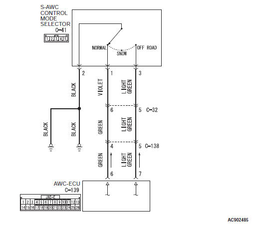
OPERATION
The AWC-ECU controls the driving mode by the signal from the S-AWC control mode selector.
DIAGNOSTIC TROUBLE CODE SET CONDITIONS
This diagnostic trouble code is set when the AWC-ECU detects that both NORMAL and OFF-ROAD are in the ON status.
PROBABLE CAUSES
- S-AWC control mode selector malfunction
- Damaged harness wires and connectors
- Malfunction of AWC-ECU
DIAGNOSTIC PROCEDURE
STEP 1. M.U.T.-III data list
Check the following data list.
- Item 41: SW1 status (NORMAL)
- Item 42: SW2 status (OFF-ROAD)
Q: Is the check result normal?
YES : Go to Step 5.
NO : Go to Step 2.
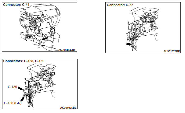
STEP 2. S-AWC control mode selector connector, intermediate connector, AWC-ECU connector check: C-41, C-32, C-138, C-139
Q: Is the check result normal?
YES : Go to Step 3.
NO : Repair the defective connector. Then go to Step 6.
STEP 3. Check the wiring harness between C-41 S-AWC control mode selector connector terminal No.1 and C-139 AWC-ECU connector terminal No.6, and between C-41 S-AWC control mode selector connector terminal No.3 and C-139 AWC-ECU connector terminal No.7.
Check the output line for short circuit.
Q: Is the check result normal?
YES : Go to Step 4.
NO : Repair the wiring harness. Then go to Step 6.
STEP 4. S-AWC control mode selector inspection
Q: Is the check result normal?
YES : Go to Step 5.
NO : Replace the S-AWC control mode selector. Then go to Step 6.
STEP 5. Check whether the diagnostic trouble code is reset.
Q: Is the diagnostic trouble code No.C1460 set? YES : Replace the AWC-ECU. Then go to Step 6.
NO : Intermittent malfunction.
STEP 6. Check whether the diagnostic trouble code is reset.
Q: Is the diagnostic trouble code No.C1460 set? YES : Return to Step 1.
NO : This diagnosis is complete.
Code No.C1610: AWC Power Supply Electronic Relay Malfunction
Electronic control coupling solenoid system circuit
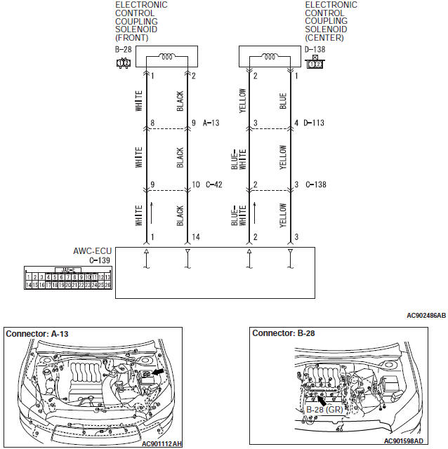
OPERATION
A relay is incorporated in AWC-ECU, and the power is supplied to the actuator via this relay.
DIAGNOSTIC TROUBLE CODE SET CONDITIONS
This diagnostic trouble code is set when the actuator power supply voltage is less than 6 V while the actuator power supply relay in the AWC-ECU is ON.
PROBABLE CAUSES
- Malfunction of AWC-ECU
- Malfunction of electronic control coupling solenoid (center)
- Malfunction of electronic control coupling solenoid (Front)
- Damaged harness wires and connectors
DIAGNOSTIC PROCEDURE
STEP 1. Electronic control coupling solenoid (front) connector, intermediate connector, AWC-ECU connector check: B-28, A-13, C-42, C-139
Q: Is the check result normal?
YES : Go to Step 2.
NO : Repair the defective connector. Then go to Step 10.
STEP 2. Check the wiring harness between B-28 electronic control coupling solenoid (front) connector terminal No.1 and C-139 AWC-ECU connector terminal No.1.
Check the power supply line for short circuit.
Q: Is the check result normal?
YES : Go to Step 3.
NO : Repair the wiring harness. Then go to Step 10.
STEP 3. Check the wiring harness between B-28 electronic control coupling solenoid (front) connector terminal No.2 and C-139 AWC-ECU connector terminal No.14.
Check the ground line for short circuit.
Q: Is the check result normal?
YES : Go to Step 4.
NO : Repair the wiring harness. Then go to Step 10.
STEP 4. Check of the electronic control coupling solenoid (Front)
Q: Is the check result normal?
YES : Go to Step 5.
NO : Replace the transfer assembly.
Then go to Step 10.
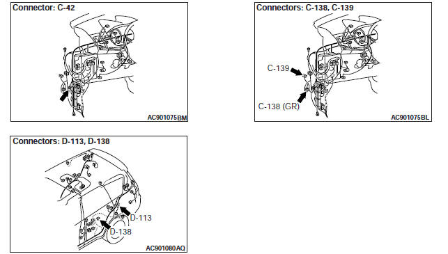
STEP 5. Electronic control coupling solenoid (center) connector, intermediate connector, AWC-ECU connector check: D-138, C-138, D-113, C-139
Q: Is the check result normal?
YES : Go to Step 6.
NO : Repair the defective connector. Then go to Step 10.
STEP 6. Check the wiring harness between D-138 electronic control coupling solenoid (center) connector terminal No.2 and C-139 AWC-ECU connector terminal No.2.
Check the power supply line for short circuit.
Q: Is the check result normal?
YES : Go to Step 7.
NO : Repair the wiring harness. Then go to Step 10.
STEP 7. Check the wiring harness between D-138 electronic control coupling solenoid (center) connector terminal No.1 and C-139 AWC-ECU connector terminal No.3.
Check the ground line for short circuit.
Q: Is the check result normal?
YES : Go to Step 8.
NO : Repair the wiring harness. Then go to Step 10.
STEP 8. Check of the electronic control coupling solenoid (center)
Q: Is the check result normal?
YES : Go to Step 9.
NO : Replace the electronic control coupling (center). Then go to Step 10.
STEP 9. Check whether the diagnostic trouble code is reset.
Q: Is diagnostic trouble code No.C1610 set? YES : Replace the AWC-ECU. Then go to Step 10.
NO : Intermittent malfunction.
STEP 10. Check whether the diagnostic trouble code is reset.
Q: Is diagnostic trouble code No.C1610 set? YES : Return to Step 1.
NO : This diagnosis is complete.
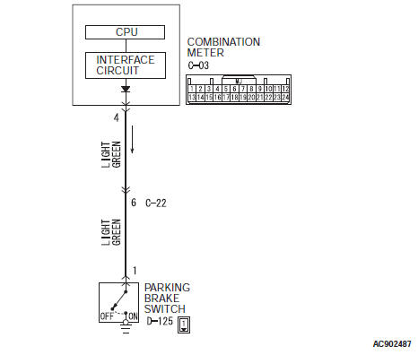
Code No.C1614: Parking Brake Switch System (Stuck On)
Parking brake switch system circuit
CAUTION
- If there is any problem in the CAN bus lines, an incorrect diagnostic trouble code may be set. Prior to this diagnosis, diagnose the CAN bus lines.
- Whenever the ECU is replaced, ensure that the CAN bus lines are normal.
OPERATION
The AWC-ECU receives the parking brake switch signal from the combination meter via CAN communication.
DIAGNOSTIC TROUBLE CODE SET CONDITIONS
This diagnostic trouble code is set when the parking brake switch ON information is received continuously for long time during driving.
PROBABLE CAUSES
- Parking brake switch malfunction
- Damaged harness wires and connectors
- Combination meter malfunction
- Malfunction of AWC-ECU
- Driving with parking brake ON
DIAGNOSTIC PROCEDURE
STEP 1. M.U.T.-III CAN bus diagnostics.
Use scan tool to perform the CAN bus diagnosis.
Q: Is the check result normal?
YES : Go to Step 3.
NO : Repair the CAN bus lines. After repairing the CAN bus line, go to Step 2.
STEP 2. Check whether the diagnostic trouble code is reset.
Q: Is diagnostic trouble code No.C1614 set? YES : Go to Step 3.
NO : This diagnosis is complete.
STEP 3. M.U.T.-III data list.
Item 29: Parking brake SW (CAN input).
Q: Is the check result normal?
YES : Go to Step 8.
NO : Go to Step 4.
STEP 4. Check the parking brake switch.
Check the parking brake switch.
Q: Is the check result normal? YES : Go to Step 5.
NO : Replace the parking brake switch. Then go to Step 8.
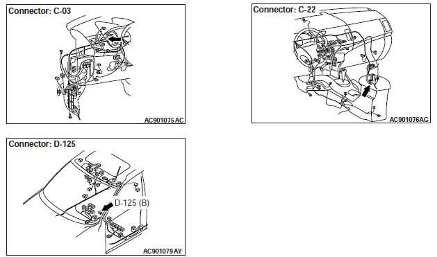
STEP 5. Combination meter connector, intermediate connector, and parking brake switch connector check: C-03, C-22, D-125
Check the contact status of the terminals.
Q: Is the check result normal?
YES : Go to Step 6.
NO : Repair the defective connector. Then go to Step 8.
STEP 6. Check the wiring harness between C-03 combination meter connector terminal No.4 and D-125 parking brake switch connector terminal No.1.
Check the power supply line for short circuit.
Q: Is the check result normal?
YES : Replace the combination meter. Then go to Step 7.
NO : Repair the wiring harness. Then go to Step 7.
STEP 7. Check whether the diagnostic trouble code is reset.
Q: Is diagnostic trouble code No.C1614 set? YES : Replace the AWC-ECU. Then go to Step 8.
NO : Intermittent malfunction.
STEP 8. Check whether the diagnostic trouble code is reset.
Q: Is diagnostic trouble code No.C1614 set? YES : Return to Step 1.
NO : This diagnosis is complete.
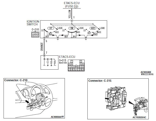
Code No.C1616: Cranking Signal System (stuck ON)
Cranking signal system circuit
CAUTION
- If there is any problem in the CAN bus lines, an incorrect diagnostic trouble code may be set. Prior to this diagnosis, diagnose the CAN bus lines.
- Whenever the ECU is replaced, ensure that the CAN bus lines are normal.
OPERATION
AWC-ECU receives the signal of the ignition switch from ETACS-ECU via CAN communication.
DIAGNOSTIC TROUBLE CODE SET CONDITIONS
This diagnostic trouble code is set when the cranking signal is continued for the specified time during driving.
PROBABLE CAUSES
- Malfunction of the ETACS-ECU
- Ignition switch malfunction
- Damaged harness wires and connectors
- Malfunction of AWC-ECU
DIAGNOSTIC PROCEDURE
STEP 1. M.U.T.-III CAN bus diagnostics.
Use scan tool to perform the CAN bus diagnosis.
Q: Is the check result normal?
YES : Go to Step 3.
NO : Repair the CAN bus lines. After repairing the CAN bus line, go to Step 2.
STEP 2. Check whether the diagnostic trouble code is reset.
Q: Is diagnostic trouble code No.C1616 set? YES : Go to Step 3.
NO : This diagnosis is complete.
STEP 3. M.U.T.-III diagnostic trouble code.
- Check the KOS diagnostic trouble code.
- Check the WCM diagnostic trouble code.
- Check the ETACS diagnostic trouble code.
Q: Is the diagnostic trouble code set? YES : Perform the relevant troubleshooting.
NO : Go to Step 4.
STEP 4. M.U.T.-III data list.
Item 30: Ignition SW (CAN input).
Q: Is the check result normal? YES : Go to Step 9.
NO : Go to Step 5.
STEP 5. Ignition switch check
- Disconnect C-210 ignition switch connector, and check the continuity between the terminals No.1 and No.5 at the ignition switch side.
- Turn the ignition switch to the "ON" position.
OK: No continuity
Q: Is the check result normal?
YES : Go to Step 6.
NO : Replace the ignition switch. Then go to Step 10.
STEP 6. Ignition switch connector, ETACS-ECU connector check: C-210, C-315
Q: Is the check result normal?
YES : Go to Step 7.
NO : Repair the defective connector. Then go to Step 10.
STEP 7. Check the wiring harness between C-210 ignition switch connector terminal No.5 and C-315 ETACS-ECU connector terminal No.7.
Check the power supply line for short (for short to the power supply) circuit.
Q: Is the check result normal?
YES : Go to Step 8.
NO : Repair the wiring harness. Then go to Step 10.
STEP 8. M.U.T.-III data list.
ETACS item No.287: Starter switch.
Q: Is the check result normal?
YES : Go to Step 9.
NO : Replace the ETACS-ECU. Then go to Step 9.
STEP 9. Check whether the diagnostic trouble code is reset.
Q: Is diagnostic trouble code No.C1616 set? YES : Replace the AWC-ECU. Then go to Step 10.
NO : Intermittent malfunction.
STEP 10. Check whether the diagnostic trouble code is reset.
Q: Is diagnostic trouble code No.C1616 set? YES : Return to Step 1.
NO : This diagnosis is complete.
READ NEXT:
 DTC No.C161F, C1621, C1624, C1626, C1627,
C1628, C1629, C1630, C1631, C1632, C1633, C2100, C2101, C2203, C2205
DTC No.C161F, C1621, C1624, C1626, C1627,
C1628, C1629, C1630, C1631, C1632, C1633, C2100, C2101, C2203, C2205
Code No.C161F: AWC actuator protection 1
CAUTION
If there is any problem in the CAN bus lines,
an incorrect diagnostic trouble code may be
set. Prior to this diagnosis, diagnose the CAN
bus lines
DTC No.U0001, U0100, U0101, U0121, U0126, U0141, U0401, U0428, U0431,
U1415, U1417, U1425, U1427, U1428
Code No.U0001: Bus-Off
CAUTION
If there is any problem in the CAN bus lines,
an incorrect diagnostic trouble code may be
set. Prior to this diagnosis, diagnose the CAN
bus lines.
Whenever the EC
Inspection Procedure
INSPECTION PROCEDURE 1: Communication between scan tool and AWC-ECU
cannot be
established
CAUTION
If there is any problem in the CAN bus lines,
an incorrect trouble symptom may occur.
Prior to th
SEE MORE:
DTC C100A, C1015, C1020, C102B, C1011, C101C, C1027, C1032, C1014,
C101F, C102A, C1035
DTC C100A: Abnormality in FL wheel speed sensor circuit
Wheel Speed Sensor Circuit
CAUTION
If there is any problem in the CAN bus lines, an incorrect
diagnostic trouble code may be set. Prior to this
diagnosis, diagnose the CAN bus lines.
Whenever ECU is replaced, ensure that the CAN bus
lin
Air purifier
An air filter has been incorporated into this air conditioning so that pollen
and dust are cleaned from the air.
Replace the air filter periodically as its ability to clean the air will be reduced
as it collects pollen and dirt. For the maintenance interval, refer to the “SERVICE
BOOKLET”
