Mitsubishi Outlander: Inspection Procedure
INSPECTION PROCEDURE 1: Communication between scan tool and AWC-ECU cannot be established
CAUTION
- If there is any problem in the CAN bus lines,
an incorrect trouble symptom may occur.
Prior to this diagnosis, always diagnose the CAN bus lines.
- Whenever the ECU is replaced, ensure that the CAN bus lines are normal.
SYMPTOMS
CAN bus line, AWC-ECU power supply circuit, or AWC-ECU may have a problem.
PROBABLE CAUSES
- Wrong M.U.T.-III wiring harness
- The CAN bus line is defective
- AWC-ECU power supply circuit malfunction
- Malfunction of AWC-ECU
- ECU malfunction of other system
DIAGNOSTIC PROCEDURE
STEP 1. M.U.T.-III CAN bus diagnostics.
Use scan tool to perform the CAN bus diagnosis.
Q: Is the check result normal?
YES : Check/repair the AWC-ECU power supply circuit.
NO : Repair the CAN bus lines.
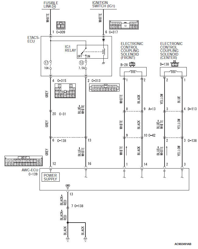
INSPECTION PROCEDURE 2 : Malfunction of power supply circuit system
Power supply system circuit

COMMENTS ON TROUBLE SYMPTOM
AWC-ECU power supply circuit, ground circuit, or AWC-ECU may have a problem.
PROBABLE CAUSES
-
Malfunction of the ETACS-ECU
-
Damaged harness wires and connectors
-
Malfunction of AWC-ECU
DIAGNOSTIC PROCEDURE
STEP 1. Check the fuse No.12, No.17
Visually check for open circuit in the fuse No.12, No.17.
Q: Is the check result normal?
YES : Go to Step 14.
NO : Go to Step 2.
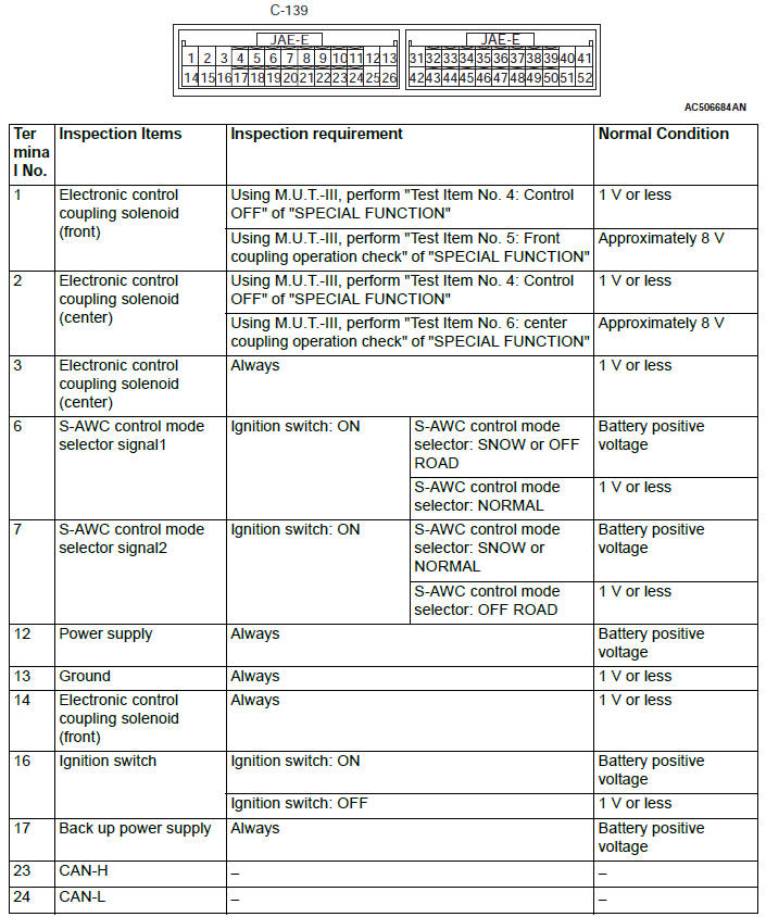
STEP 2. Electronic control coupling solenoid (front) connector, intermediate connector, AWC-ECU connector check: B-28, A-13, C-42, C-139
Q: Is the check result normal? YES : Go to Step 3.
NO : Repair the defective connector. Then go to Step 26.
STEP 3. Check the wiring harness between B-28 electronic control coupling solenoid (front) connector terminal No.1 and C-139 AWC-ECU connector terminal No.1.
Check the power supply line for short circuit.
Q: Is the check result normal?
YES : Go to Step 4.
NO : Repair the wiring harness. Then go to Step 26.
STEP 4. Check the wiring harness between B-28 electronic control coupling solenoid (front) connector terminal No.2 and C-139 AWC-ECU connector terminal No.14.
Check the ground line for short circuit.
Q: Is the check result normal?
YES : Go to Step 5.
NO : Repair the wiring harness. Then go to Step 26.
STEP 5. Check of the electronic control coupling solenoid (Front)
Q: Is the check result normal? YES : Go to Step 6.
NO : Replace the transfer assembly.
Then go to Step 26.
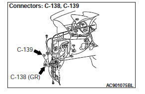
STEP 6. Electronic control coupling solenoid (center) connector, intermediate connector, AWC-ECU connector check: D-138, C-138, D-113, C-139
Q: Is the check result normal? YES : Go to Step 7.
NO : Repair the defective connector. Then go to Step 26.
STEP 7. Check the wiring harness between D-138 electronic control coupling solenoid (center) connector terminal No.2 and C-139 AWC-ECU connector terminal No.2.
Check the power supply line for short circuit.
Q: Is the check result normal?
YES : Go to Step 8.
NO : Repair the wiring harness. Then go to Step 26.
STEP 8. Check the wiring harness between D-138 electronic control coupling solenoid (center) connector terminal No.1 and C-139 AWC-ECU connector terminal No.3.
Check the ground line for short circuit.
Q: Is the check result normal?
YES : Go to Step 9.
NO : Repair the wiring harness. Then go to Step 26.
STEP 9. Check of the electronic control coupling solenoid (center)
Q: Is the check result normal? YES : Go to Step 10.
NO : Replace the electronic control coupling (center). Then go to Step 26.
STEP 10. Intermediate connector, AWC-ECU connector, ETACS-ECU connector check: C-31, C-138, C-139, C-315
Q: Is the check result normal?
YES : Go to Step 11.
NO : Repair the defective connector. Then go to Step 26.
STEP 11. Check the wiring harness between C-139 AWC-ECU connector terminal No.12 and C-315 ETACS-ECU connector terminal No.4.
Check the power supply line for short circuit.
Q: Is the check result normal?
YES : Go to Step 12.
NO : Repair the wiring harness, and then replace the fuse No.17. Then go to Step 26.
STEP 12. Intermediate connector, AWC-ECU connector, ETACS-ECU connector check: C-138, C-139, C-313
Q: Is the check result normal?
YES : Go to Step 13.
NO : Repair the defective connector. Then go to Step 26.
STEP 13. Check the wiring harness between C-139 AWC-ECU connector terminal No.16 and C-313 ETACS-ECU connector terminal No.2.
Check the power supply line for short circuit.
Q: Is the check result normal?
YES : Replace the fuse No.12, No.17. Then go to Step 24.
NO : Repair the wiring harness, and then replace the fuse No.12. Then go to Step 26.
STEP 14. Voltage measurement at C-309 ETACS-ECU connector
Disconnect the connector, and measure the voltage between terminal No.1 and ground at the wiring harness side.
OK: Battery positive voltage Q: Is the check result normal?
YES : Go to Step 16.
NO : Go to Step 15.
STEP 15. ETACS-ECU connector check: C-309
Q: Is the check result normal?
YES : The short or open circuit may be present in the power supply circuit. Repair the wiring harness between the C-309 ETACS-ECU connector terminal No.1 and fusible link No.34. Then go to Step 26.
NO : Repair the defective connector. Then go to Step 26.
STEP 16. Voltage measurement at C-317 ETACS-ECU connector
- Disconnect the connector, and measure the voltage between terminal No.6 and ground at the wiring harness side.
- Turn the ignition switch to the "ON" position.
OK: Battery positive voltage
Q: Is the check result normal?
YES : Go to Step 18.
NO : Go to Step 17.
STEP 17. ETACS-ECU connector check: C-317
Q: Is the check result normal?
YES : The short or open circuit may be present in the power supply circuit. Repair the wiring harness between the C-317 ETACS-ECU connector terminal No.6 and ignition switch. Then go to Step 26.
NO : Repair the defective connector. Then go to Step 26.
STEP 18. Voltage measurement at C-139 AWC-ECU connector
Disconnect the connector, and measure the voltage between terminal No.12 and ground at the wiring harness side.
OK: Battery positive voltage
Q: Is the check result normal? YES : Go to Step 20.
NO : Go to Step 19.
STEP 19. Intermediate connector, AWC-ECU connector, ETACS-ECU connector check: C-31, C-138, C-139, C-315
Q: Is the check result normal?
YES : The open circuit may be present in the power supply circuit. Repair the wiring harness between the C-139 AWC-ECU connector terminal No.12 and C-315 ETACS-ECU connector terminal No.4. Then go to Step 26.
NO : Repair the defective connector. Then go to Step 26.
STEP 20. Voltage measurement at C-139 AWC-ECU connector
- Disconnect the connector, and measure the voltage between terminal No.16 and ground at the wiring harness side.
- Turn the ignition switch to the "ON" position.
OK: Battery positive voltage
Q: Is the check result normal? YES : Go to Step 22.
NO : Go to Step 21.
STEP 21. Intermediate connector, AWC-ECU connector, ETACS-ECU connector check: C-138, C-139, C-313
Q: Is the check result normal?
YES : The open circuit may be present in the power supply circuit. Repair the wiring harness between the C-139 AWC-ECU connector terminal No.16 and C-313 ETACS-ECU connector terminal No.2. Then go to Step 26.
NO : Repair the defective connector. Then go to Step 26.
STEP 22. Resistance measurement at C-139 AWC-ECU connector
Disconnect the connector, and measure the resistance between terminal No.13 and ground at the wiring harness side.
OK: Continuity (Less than 2 Ω)
Q: Is the check result normal?
YES : Go to Step 24.
NO : Go to Step 23.
STEP 23. Intermediate connector, AWC-ECU connector check: C-138, C-139
Q: Is the check result normal?
YES : The open circuit may be present in the ground circuit.
Repair the wiring harness between the C-139 AWC-ECU connector terminal No.13 and body ground. Then go to Step 26.
NO : Repair the defective connector. Then go to Step 26.
STEP 24. Retest the system.
Q: Is the check result normal?
YES : Intermittent malfunction.
NO : Replace the ETACS-ECU. Then go to Step 25.
STEP 25. Retest the system.
Q: Is the check result normal?
YES : Intermittent malfunction.
NO : Replace the AWC-ECU.
STEP 26. Retest the system.
Q: Is the check result normal?
YES : This diagnosis is complete.
NO : Return to Step 1.
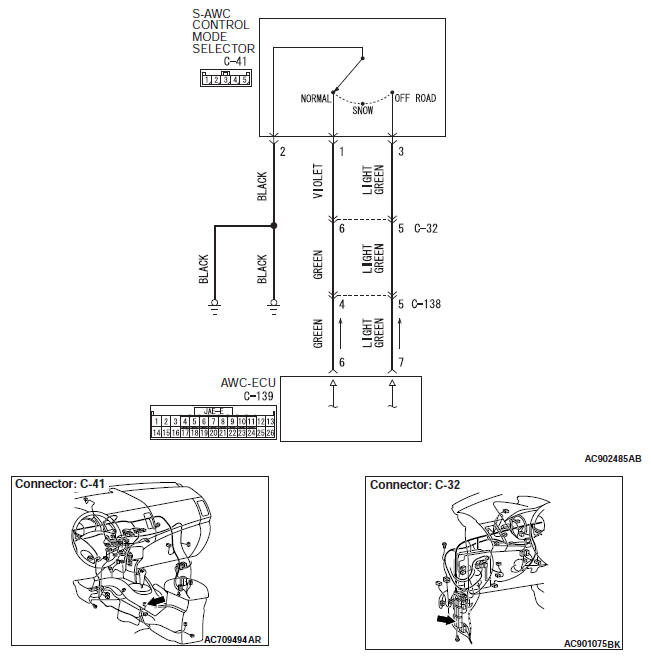
INSPECTION PROCEDURE 3: Shifting the S-AWC control mode selector does not change the mode
S-AWC drive mode selector system circuit
CAUTION
- If there is any problem in the CAN bus lines,
an incorrect trouble symptom may occur.
Prior to this diagnosis, always diagnose the CAN bus lines.
- Whenever the ECU is replaced, ensure that the CAN bus lines are normal.
SYMPTOMS
S-AWC control mode selector or AWC-ECU may have a problem.
PROBABLE CAUSES
- S-AWC control mode selector malfunction
- Malfunction of the combination meter
- Damaged harness wires and connectors
- Malfunction of AWC-ECU
DIAGNOSTIC PROCEDURE
STEP 1. M.U.T.-III CAN bus diagnostics.
Use scan tool to perform the CAN bus diagnosis.
Q: Is the check result normal?
YES : Go to Step 3.
NO : Repair the CAN bus lines. After repairing the CAN bus line, go to Step 2.
STEP 2. Retest the system.
Q: Is the check result normal?
YES : Intermittent malfunction.
NO : Go to Step 3.
STEP 3. M.U.T.-III actuator test.
Combination meter item No.2: LCD(AUTO).
Q: Is the check result normal?
YES : Go to Step 4.
NO : Replace the combination meter. Then go to Step 13.
STEP 4. S-AWC control mode selector inspection
Q: Is the check result normal?
YES : Go to Step 5.
NO : Replace the S-AWC control mode selector. Then go to Step 13.
STEP 5. Measure the voltage at C-41 S-AWC control mode selector connector.
- Disconnect the connector, and measure the voltage between terminal No.1, No.3 and ground at the harness side.
- Turn the ignition switch to the "ON" position.
OK: Battery positive voltage
Q: Is the check result normal?
YES : Go to Step 8.
NO : Go to Step 6.
STEP 6. S-AWC control mode selector connector, intermediate connector, AWC-ECU connector check: C-41, C-32, C-138, C-139
Q: Is the check result normal?
YES : Go to Step 7.
NO : Repair the defective connector. Then go to Step 13.
STEP 7. Check the wiring harness between C-41 S-AWC control mode selector connector terminal No.1 and C-139 AWC-ECU connector terminal No.6, and between C-41 S-AWC control mode selector connector terminal No.3 and C-139 AWC-ECU connector terminal No.7.
Check the output line for short or open circuit.
Q: Is the check result normal?
YES : Go to Step 11.
NO : Repair the wiring harness. Then go to Step 13.
STEP 8. Measure the resistance at C-41 S-AWC control mode selector connector.
Disconnect the connector, and measure the resistance between terminal No.2 and ground at the harness side.
OK: Continuity (Less than 2 Ω)
Q: Is the check result normal?
YES : Go to Step 11.
NO : Go to Step 9.
STEP 9. S-AWC control mode selector connector check: C-41
Q: Is the check result normal?
YES : Go to Step 10.
NO : Repair the defective connector. Then go to Step 13.
STEP 10. Check the wiring harness between C-41 S-AWC control mode selector connector terminal No.2 and body ground.
Check the ground line for open circuit.
Q: Is the check result normal?
YES : Go to Step 11.
NO : Repair the wiring harness. Then go to Step 13.
STEP 11. M.U.T.-III data list.
Check the following data list.
- Item 41: SW1 status (NORMAL)
- Item 42: SW2 status (OFF LOAD)
Q: Is the check result normal?
YES : Go to Step 13.
NO : Go to Step 12.
STEP 12. Retest the system.
Q: Is the check result normal?
YES : Intermittent malfunction.
NO : Replace the AWC-ECU. Then go to Step 13.
STEP 13. Retest the system.
Q: Is the check result normal?
YES : This diagnosis is complete.
NO : Return to Step 1.
INSPECTION PROCEDURE 4: The tight corner braking phenomenon (difficult to turn) appears frequently with the S-AWC control mode selector in the NORMAL or SNOW mode
CAUTION
- If there is any problem in the CAN bus lines,
an incorrect trouble symptom may occur.
Prior to this diagnosis, always diagnose the CAN bus lines.
- Whenever the ECU is replaced, ensure that the CAN bus lines are normal.
SYMPTOMS
The electronic control coupling (Front), electronic control coupling (center) or AWC-ECU may have a problem.
PROBABLE CAUSES
- Malfunction of electronic control coupling (Front)
- Malfunction of electronic control coupling (center)
- Damaged harness wires and connectors
- Malfunction of AWC-ECU
DIAGNOSTIC PROCEDURE
STEP 1. M.U.T.-III CAN bus diagnostics.
Use scan tool to perform the CAN bus diagnosis.
Q: Is the check result normal?
YES : Go to Step 3.
NO : Repair the CAN bus lines. After repairing the CAN bus line, go to Step 2.
STEP 2. Retest the system.
Q: Is the check result normal?
YES : Intermittent malfunction.
NO : Go to Step 3.
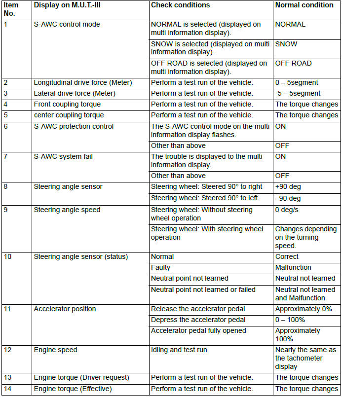
STEP 3. M.U.T.-III data list
Item 1: S-AWC control mode.
Q: Is the check result normal?
YES : Go to Step 4.
NO : Check/repair the S-AWC control mode selector. Then go to Step 9.
STEP 4. Check of the electronic control coupling (Front)
Q: Is the check result normal?
YES : Go to Step 5.
NO : Replace the transfer assembly.
Then go to Step 9.
STEP 5. Check of the electronic control coupling (center)
Q: Is the check result normal?
YES : Go to Step 6.
NO : Replace the electronic control coupling (center). Then go to Step 9.
STEP 6. M.U.T.-III data list
Item No.13: Engine torque (Driver request).
Q: Is the check result normal?
YES : Go to Step 7.
NO : Perform the troubleshooting for the engine. Then go to Step 9.
STEP 7. M.U.T.-III data list
Check the following data list.
- Item No.8: Steering angle sensor
- Item No.21: Wheel speed sensor <FL>
- Item No.22: Wheel speed sensor <FR>
- Item No.23: Wheel speed sensor <RL>
- Item No.24: Wheel speed sensor <RR>
- Item No.25: Yaw rate sensor
- Item No.26: Lateral G sensor
Q: Is the check result normal?
YES : Go to Step 8.
NO : Perform the troubleshooting for the ASC. Then go to Step 9.
STEP 8. Retest the system.
Q: Is the check result normal?
YES : Intermittent malfunction.
NO : Replace the AWC-ECU. Then go to Step 9.
STEP 9. Retest the system.
Q: Is the check result normal?
YES : This diagnosis is complete.
NO : Return to Step 1.
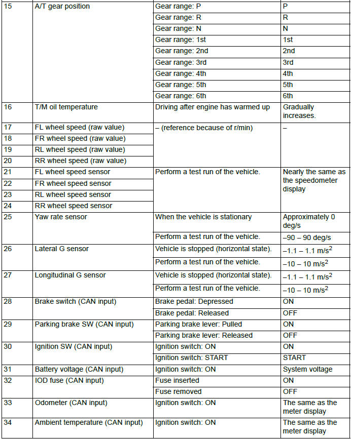
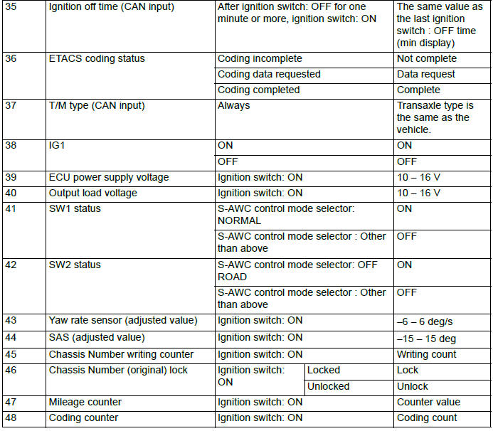
DATA LIST REFERENCE TABLE
SPECIAL FUNCTION
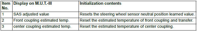
RESET
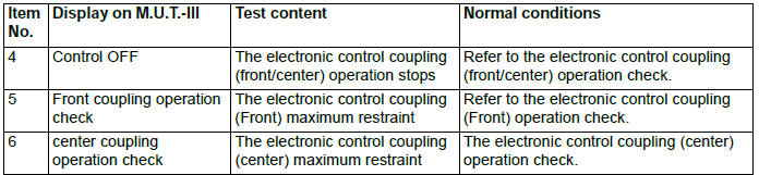
TEST
1. The test can be performed only when all the following conditions are satisfied.
- Every wheel speed sensor input is 20 km/h (12 mph) or less.
- No system malfunction is detected.
- The steering angle of steering wheel is within +-30º from the neutral position.
2. With the test, when any of the conditions below is met, the forced activation will be cancelled.
- Any of the wheel speed sensors detects an input of 20 km/h (12 mph) or more (excluding item No.4 "Control OFF").
- A system malfunction is detected.
- The forced activation time has elapsed.
- M.U.T.-III is removed.
- M.U.T.-III clear key is operated.
CHECK AT AWC-ECU TERMINAL
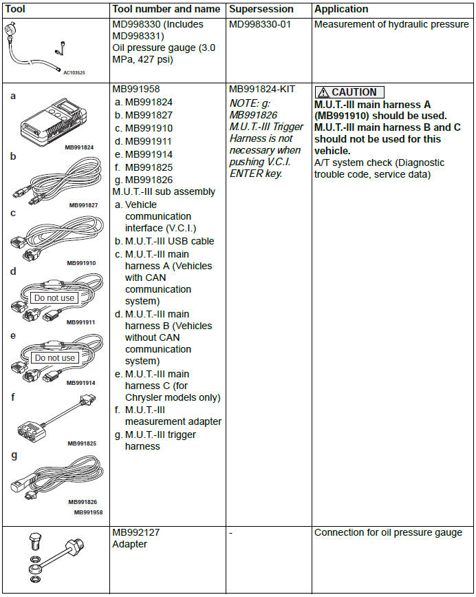
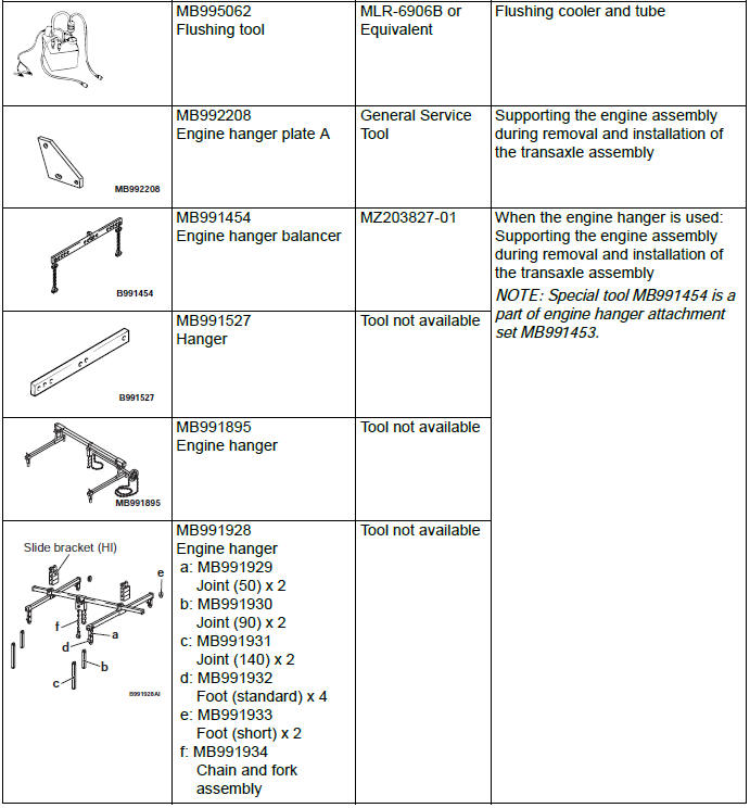
Special Tools
READ NEXT:
 On-vehicle Service
A/T CONTROL COMPONENT LAYOUT
ESSENTIAL SERVICE
TRANSMISSION FLUID CHECK
1. Drive the vehicle until the transmission fluid temperature
rises to the normal operating temperature [70 − 80ºC (
Transaxle Control
REMOVAL AND INSTALLATION
WARNING
When removing and installing the transaxle
control cable and shift lock cable unit, be
careful not to hit the SRS-ECU.
Pre-removal operation
Front floor console asse
Transaxle Assembly
REMOVAL AND INSTALLATION
Pre-removal operation
Engine compartment under cover and side cover removal
Transmission fluid draining
Air cleaner bracket removal
Battery and Battery Tray Removal
ECM
SEE MORE:
Crankshaft and Cylinder Block
REMOVAL AND INSTALLATION
Removal steps
Crankshaft bearing cap bolt
Crankshaft bearing cap
Crankshaft bearing lower
Crankshaft
Crankshaft bearing upper
Thrust bearing
Crankshaft sensing ring
Cylinder block
REMOVAL SERVICE POINT
CRANKSHAFT REMOVAL
When temporarily placing the crankshaft wit
On-vehicle Service
CONTROL SYSTEM COMPONENT PART CONFIGURATION DIAGRAM
ESSENTIAL SERVICE
TRANSMISSION FLUID CHECK
CAUTION
Replace the transmission fluid whenever the transaxle is
replaced with a new one or the vehicle is driven in harsh
conditions.
1. Drive the vehicle until the transmission fluid is warmed up t
