Mitsubishi Outlander: Diagnostic Trouble Code Procedures
DTC B16A2: Blown turn-signal light (LH) bulb
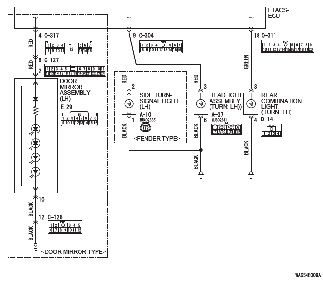
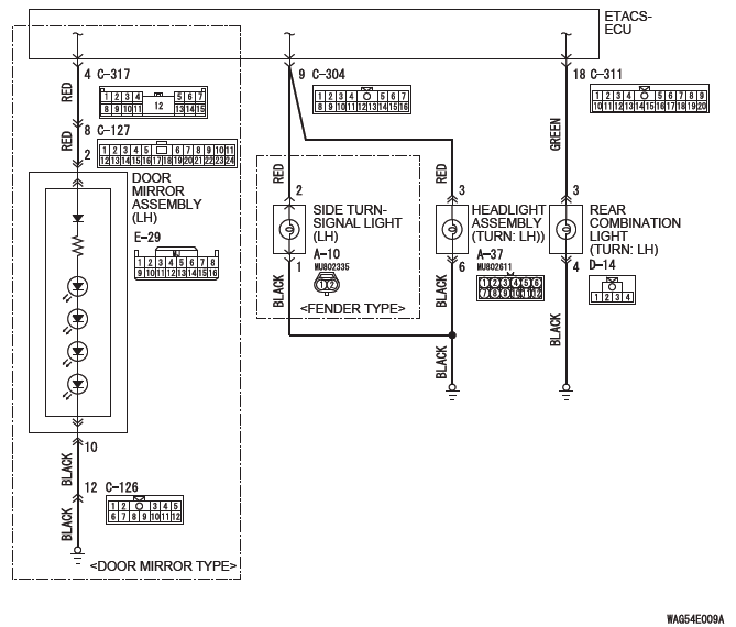
Turn-Signal Light Circuit (LH)
TROUBLE JUDGMENT
When the left bulb of turn-signal light is blown, the ETACS-ECU sets DTC B16A2.
TECHNICAL DESCRIPTION (COMMENT)
The ETACS-ECU sets DTC B16A2 under the following conditions.
- If there is a malfunction to the left turn-signal light bulb, the blown left bulb counter counts once when the illumination of hazard or turn-signal light (left side) is attempted.
- After the bulb counter reaches "3," DTC B16A2 is set.
TROUBLESHOOTING HINTS
- Malfunction of turn-signal light bulb (left)
- Malfunction of the ETACS-ECU
- The wiring harness or connectors may have loose, corroded, or damaged terminals, or terminals pushed back in the connector
DIAGNOSIS
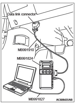
Required Special Tools:
- MB991958: Scan Tool (M.U.T.-III Sub Assembly)
- MB991824: Vehicle Communication Interface (V.C.I.)
- MB991827: M.U.T.-III USB Cable
- MB991910: M.U.T.-III Main Harness A (Vehicles with CAN communication system)
STEP 1. Bulb check.
Check whether the left turn-signal light illuminates normally.
Q: Is the check result normal?
YES : Go to Step 2.
NO : Replace the bulb of turn-signal light which does not illuminate.
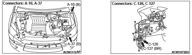
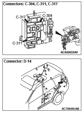
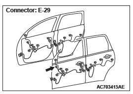
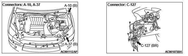
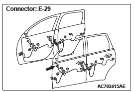
STEP 2. Check headlight assembly (LH) connector A-37, side turn-signal light (LH) connector A-10 <fender type>, door mirror assembly (LH) connector E-29 <door mirror type>, rear combination light (LH) connector D-14 for loose, corroded or damaged terminals, or terminals pushed back in the connector.
Q: Are headlight assembly (LH) connector A-37, side turn-signal light (LH) connector A-10 <fender type>, door mirror assembly (LH) connector E-29 <door mirror type>, rear combination light (LH) connector D-14 in good condition?
YES : Go to Step 3.
NO : Repair the damaged parts.
STEP 3. Resistance measurement at headlight assembly (LH) connector A-37, side turn-signal light (LH) connector A-10 <fender type>, door mirror assembly (LH) connector E-29 <door mirror type>, rear combination light (LH) connector D-14.
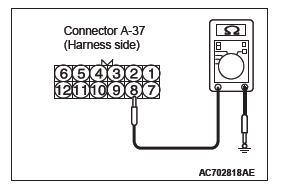
(1) Disconnect the connector, and measure at the wiring harness side.
(2) Measure the resistance between the connector terminal of light which does not illuminate and ground.
- Measure the resistance between the headlight assembly (LH) connector A-37 (terminal No. 6) and body ground.
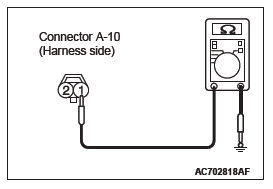
- Measure the resistance between side turn-signal light
(LH) connector A-10 (terminal No. 1) and body ground.
<fender type>
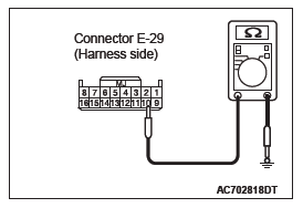
- Measure the resistance between door mirror assembly
(LH) connector E-29 (terminal No. 10) and body ground.
<door mirror type>
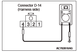
- Measure the resistance between rear combination light
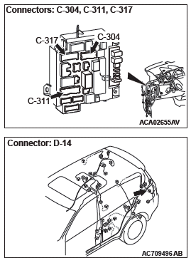
(LH) connector D-14 (terminal No. 4) and body ground.
The measured value should be 2 Ω or less.
Q: Does the measured resistance value correspond with this range?
YES : Go to Step 5.
NO : Go to Step 4.
STEP 4. Check the wiring harness between headlight assembly (LH) connector A-37 (terminal No. 6), side turn-signal light (LH) connector A-10 (terminal No. 1) <fender type>, door mirror assembly (LH) connector E-29 (terminal No. 10) <door mirror type>, rear combination light (LH) connector D-14 (terminal No. 4) and ground.
Check the ground wires for open circuit.
NOTE: Also check intermediate connector C-126 <door mirror type> for loose, corroded, or damaged terminals, or terminals pushed back in the connector. If intermediate connector C-126 <door mirror type> is damaged, repair or replace the connector as described in GROUP 00E, Harness Connector Inspection.
Q: Are the wiring harness between headlight assembly (LH) connector A-37 (terminal No. 6), side turn-signal light (LH) connector A-10 (terminal No. 1) <fender type>, door mirror assembly (LH) connector E-29 (terminal No.
10) <door mirror type>, rear combination light (LH) connector D-14 (terminal No. 4) and ground in good condition?
YES : Go to Step 7.
NO : Repair the wiring harness.
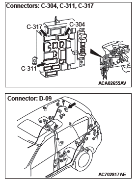
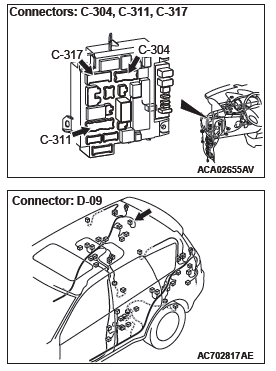
STEP 5. Check ETACS-ECU connectors C-304, C-311 and C-317 <door mirror type> for loose, corroded or damaged terminals, or terminals pushed back in the connector.
Q: Are ETACS-ECU connectors C-304, C-311 and C-317 in good condition?
YES : Go to Step 6.
NO : Repair the damaged parts.
STEP 6. Check the wiring harness between headlight assembly (LH) connector A-37 (terminal No. 3), side turn-signal light (LH) connector A-10 (terminal No. 2) <fender type>, door mirror assembly (LH) connector E-29 (terminal No. 2) <door mirror type>, rear combination light (LH) connector D-14 (terminal No. 3) and ETACS-ECU connector C-304 (terminal No. 9), ETACS-ECU connector C-311 (terminal No. 18) or ETACS-ECU connector C-317 (terminal No. 4).
Check the communication line for open circuit.
NOTE: Also check intermediate connector C-127 <door mirror type> for loose, corroded, or damaged terminals, or terminals pushed back in the connector. If intermediate connector C-127 <door mirror type> is damaged, repair or replace the connector as described in GROUP 00E, Harness Connector Inspection.
Q: Are the wiring harness between headlight assembly (LH) connector A-37 (terminal No. 3), side turn-signal light (LH) connector A-10 (terminal No. 2) <fender type>, door mirror assembly (LH) connector E-29 (terminal No.2) <door mirror type>, rear combination light (LH) connector D-14 (terminal No. 3) and ETACS-ECU connector C-304 (terminal No. 9), ETACS-ECU connector C-311 (terminal No. 18) or ETACS-ECU connector C-317 (terminal No. 4) in good condition?
YES : Go to Step 7.
NO : Repair the wiring harness.
STEP 7. Using scan tool MB991958, Check whether the diagnostic trouble code is reset.
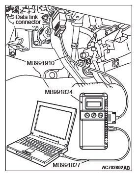
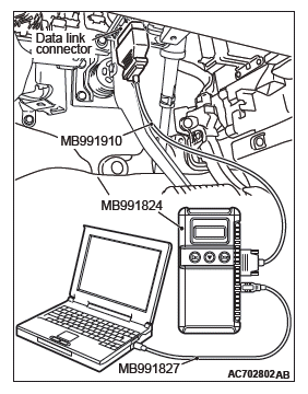
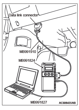
CAUTION To prevent damage to scan tool MB991958, always turn the ignition switch to the "LOCK" (OFF) position before connecting or disconnecting scan tool MB991958.
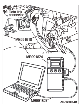
(1) Connect scan tool MB991958. Refer to "How to connect scan tool ".
(2) Turn the ignition switch to the "ON" position.
(3) Erase the DTC.
(4) Turn the ignition switch from "LOCK" (OFF) position to "ON" position.
(5) Check whether the ETACS-ECU DTC is set.
Q: Is the DTC set?
YES : Replace the ETACS-ECU.
NO : The procedure is complete.
DTC B16A3: Turn-signal light (LH) short circuit
Turn-Signal Light Circuit (LH)
TROUBLE JUDGMENT
When the left wiring harness of turn-signal light is short circuited, the ETACS-ECU sets DTC B16A3.
TECHNICAL DESCRIPTION (COMMENT)
When the short circuit is detected three times consecutively, the ETACS-ECU sets the DTC B16A3.
TROUBLESHOOTING HINTS
- The wiring harness or connectors may have loose, corroded, or damaged terminals, or terminals pushed back in the connector
- Malfunction of the ETACS-ECU
DIAGNOSIS
Required Special Tools:
- MB992006: Extra fine probe
- MB991223: Harness set
- MB991958: Scan Tool (M.U.T.-III Sub Assembly)
- MB991824: Vehicle Communication Interface (V.C.I.)
- MB991827: M.U.T.-III USB Cable
- MB991910: M.U.T.-III Main Harness A (Vehicles with CAN communication system)
STEP 1. Check headlight assembly (LH) connector A-37, side turn-signal light (LH) connector A-10 <fender type>, door mirror assembly (LH) connector E-29 <door mirror type>, rear combination light (LH) connector D-14 for loose, corroded or damaged terminals, or terminals pushed back in the connector.
Q: Are headlight assembly (LH) connector A-37, side turn-signal light (LH) connector A-10 <fender type>, door mirror assembly (LH) connector E-29 <door mirror type>, rear combination light (LH) connector D-14 in good condition?
YES : Go to Step 2.
NO : Repair the damaged parts.
STEP 2. Check ETACS-ECU connectors C-304, C-311 and C-317 <door mirror type> for loose, corroded or damaged terminals, or terminals pushed back in the connector.
Q: Are ETACS-ECU connectors C-304, C-311 and C-317 <door mirror type> in good condition?
YES : Go to Step 3.
NO : Repair the damaged parts.
STEP 3. Check the wiring harness between headlight assembly (LH) connector A-37 (terminal No. 3), side turn-signal light (LH) connector A-10 (terminal No. 2) <fender>, door mirror assembly (LH) connector E-29 (terminal No. 2) <door mirror type>, rear combination light (LH) connector D-14 (terminal No. 3) and ETACS-ECU connector C-304 (terminal No. 9), ETACS-ECU connector C-311 (terminal No. 18) or ETACS-ECU connector C-317 (terminal No. 4).
Check the communication line for short circuit.
NOTE: Also check intermediate connector C-127 <door mirror type> for loose, corroded, or damaged terminals, or terminals pushed back in the connector. If intermediate connector C-127 <door mirror type> is damaged, repair or replace the connector as described in GROUP 00E, Harness Connector Inspection.
Q: Are the wiring harness between headlight assembly (LH) connector A-37 (terminal No. 3), side turn-signal light (LH) connector A-10 (terminal No. 2) <fender>, door mirror assembly (LH) connector E-29 (terminal No. 2) <door mirror type>, rear combination light (LH) connector D-14 (terminal No. 3) and ETACS-ECU connector C-304 (terminal No. 9), ETACS-ECU connector C-311 (terminal No. 18) or ETACS-ECU connector C-317 (terminal No. 4) in good condition?
YES : Go to Step 4.
NO : Repair the wiring harness.
STEP 4. Using scan tool MB991958, Check whether the diagnostic trouble code is reset.
CAUTION To prevent damage to scan tool MB991958, always turn the ignition switch to the "LOCK" (OFF) position before connecting or disconnecting scan tool MB991958.
(1) Connect scan tool MB991958. Refer to "How to connect scan tool ".
(2) Turn the ignition switch to the "ON" position.
(3) Erase the DTC.
(4) Turn the ignition switch from "LOCK" (OFF) position to "ON" position.
(5) Check if DTC is set.
Q: Is the DTC set?
YES : Replace the ETACS-ECU.
NO : The procedure is complete.
DTC B16A4: Blown turn-signal light (RH) bulb
Turn-Signal Light Circuit (RH)
DIAGNOSTIC FUNCTION
When the right bulb of turn-signal light is blown, the ETACS-ECU sets DTC B16A4.
TECHNICAL DESCRIPTION (COMMENT)
The ETACS-ECU sets DTC B16A4 under the following conditions.
- If there is a malfunction to the right turn-signal light bulb, the blown right bulb counter counts once when the illumination of hazard or turn-signal light (right side) is attempted.
- If the blown right bulb counter reaches "3," the DTC B16A4 is set.
TROUBLESHOOTING HINTS
- Malfunction of turn-signal light bulb (right side)
- Malfunction of the ETACS-ECU
- The wiring harness or connectors may have loose, corroded, or damaged terminals, or terminals pushed back in the connector
DIAGNOSIS
Required Special Tools:
- MB991958: Scan Tool (M.U.T.-III Sub Assembly)
- MB991824: Vehicle Communication Interface (V.C.I.)
- MB991827: M.U.T.-III USB Cable
- MB991910: M.U.T.-III Main Harness A (Vehicles with CAN communication system)
STEP 1. Bulb check.
Check whether the bulb of turn-signal light which does not illuminate is normal.
Q: Is the check result normal?
YES : Go to Step 2.
NO : Replace the bulb of turn-signal light which does not illuminate.
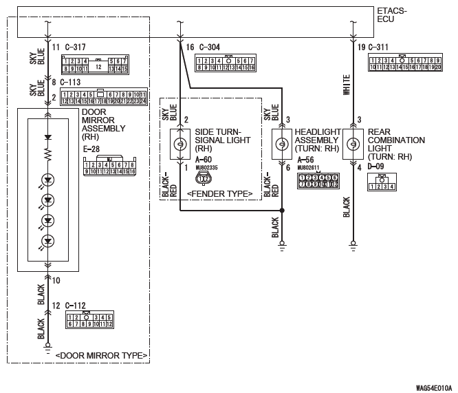
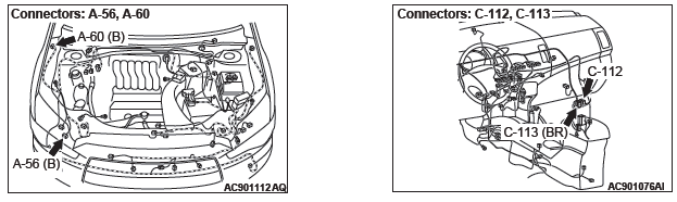
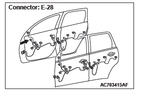
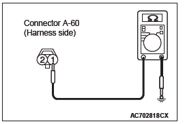
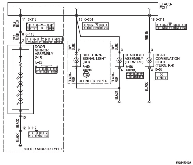
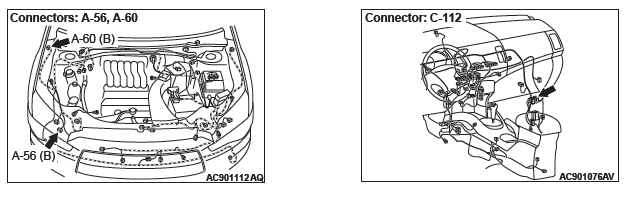
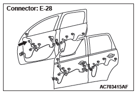
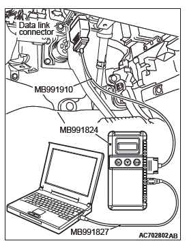
STEP 2. Check headlight assembly (RH) connector A-56, side turn-signal light (RH) connector A-60 <fender type>, door mirror assembly (RH) connector E-28 <door mirror type>, rear combination light (RH) connector D-09 for loose, corroded or damaged terminals, or terminals pushed back in the connector.
Q: Are headlight assembly (RH) connector A-56, side turn-signal light (RH) connector A-60 <fender type>, door mirror assembly (RH) connector E-28 <door mirror type>, rear combination light (RH) connector D-09 in good condition?
YES : Go to Step 3.
NO : Repair the damaged parts.
STEP 3. Resistance measurement at headlight assembly (RH) connector A-56, side turn-signal light (RH) connector A-60 <fender type>, door mirror assembly (RH) connector E-28 <door mirror type>, rear combination light (RH) connector D-09.

(1) Disconnect the connector, and measure at the wiring harness side.
(2) Measure the resistance between the connector terminal of light which does not illuminate and body ground.
- Measure the resistance between the headlight assembly (RH) connector A-56 (terminal No. 6) and body ground.
- Measure the resistance between the side turn-signal light (RH) connector A-60 (terminal No. 1) and body ground.
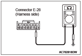
- Measure the resistance between door mirror assembly
(RH) connector E-28 (terminal No. 10) and body ground.
<door mirror type>
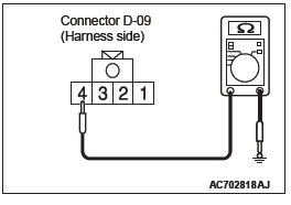
- Measure the resistance between the rear combination
light (RH) connector D-09 (terminal No. 4) and body
ground.
The measured value should be continuity exists (2 Ω or less).
Q: Does the measured resistance value correspond with this range?
YES : Go to Step 5.
NO : Go to Step 4.
STEP 4. Check the wiring harness between headlight assembly (RH) connector A-56 (terminal No. 6), side turn-signal light (RH) connector A-60 (terminal No. 1) <fender type>, door mirror assembly (RH) connector E-28 (terminal No. 10) <door mirror type>, rear combination light (LH) connector D-09 (terminal No. 4) and ground.
Check the ground wires for open circuit.
NOTE: Also check intermediate connector C-112 <door mirror type> for loose, corroded, or damaged terminals, or terminals pushed back in the connector. If intermediate connector C-112 <door mirror type> is damaged, repair or replace the connector as described in GROUP 00E, Harness Connector Inspection.
Q: Are the wiring harness between headlight assembly (RH) connector A-56 (terminal No. 6), side turn-signal light (RH) connector A-60 (terminal No. 1) <fender type>, door mirror assembly (RH) connector E-28 (terminal No.10) <door mirror type>, rear combination light (LH) connector D-09 (terminal No. 4) and ground in good condition?
YES : Go to Step 7.
NO : Repair the wiring harness.
STEP 5. Check ETACS-ECU connectors C-304, C-311 and C-317 <door mirror type> for loose, corroded or damaged terminals, or terminals pushed back in the connector.
Q: Are ETACS-ECU connectors C-304, C-311 and C-317 in good condition?
YES : Go to Step 6.
NO : Repair the damaged parts.
STEP 6. Check the wiring harness between headlight assembly (RH) connector A-56 (terminal No. 3), side turn-signal light (RH) connector A-60 (terminal No. 2) <fender type>, door mirror assembly (RH) connector E-28 (terminal No. 2) <door mirror type>, rear combination light (RH) connector D-09 (terminal No. 3) and ETACS-ECU connector C-304 (terminal No. 16), ETACS-ECU connector C-311 (terminal No. 19) or ETACS-ECU connector C-317 (terminal No. 11).
Check the communication line for open circuit.
NOTE: Also check intermediate connector C-113 <door mirror type> for loose, corroded, or damaged terminals, or terminals pushed back in the connector. If intermediate connector C-113 <door mirror type> is damaged, repair or replace the connector as described in GROUP 00E, Harness Connector Inspection.
Q: Are the wiring harness between headlight assembly (RH) connector A-56 (terminal No. 3), side turn-signal light (RH) connector A-60 (terminal No. 2) <fender type>, door mirror assembly (RH) connector E-28 (terminal No.2) <door mirror type>, rear combination light (RH) connector D-09 (terminal No. 3) and ETACS-ECU connector C-304 (terminal No. 16), ETACS-ECU connector C-311 (terminal No. 19) or ETACS-ECU connector C-317 (terminal No. 11) in good condition?
YES : Go to Step 7.
NO : Repair the wiring harness.
STEP 7. Using scan tool MB991958, Check whether the diagnostic trouble code is reset.
CAUTION To prevent damage to scan tool MB991958, always turn the ignition switch to the "LOCK" (OFF) position before connecting or disconnecting scan tool MB991958.
(1) Connect scan tool MB991958. Refer to "How to connect scan tool ".
(2) Turn the ignition switch to the "ON" position.
(3) Erase the DTC.
(4) Turn the ignition switch from "LOCK" (OFF) position to "ON" position.
(5) Check if DTC is set.
Q: Is the DTC set?
YES : Replace the ETACS-ECU.
NO : The procedure is complete.
DTC B16A5: Turn-signal light (RH) short circuit
Turn-Signal Light Circuit (RH)
TROUBLE JUDGMENT
When the right wiring harness of turn-signal light is short circuited, the ETACS-ECU sets DTC B16A5.
TECHNICAL DESCRIPTION (COMMENT)
When the short circuit is detected three times consecutively, the ETACS-ECU sets the DTC B16A5.
TROUBLESHOOTING HINTS
- The wiring harness or connectors may have loose, corroded, or damaged terminals, or terminals pushed back in the connector
- Malfunction of the ETACS-ECU
DIAGNOSIS
Required Special Tools:
- MB992006: Extra fine probe
- MB991223: Harness set
- MB991958: Scan Tool (M.U.T.-III Sub Assembly)
- MB991824: Vehicle Communication Interface (V.C.I.)
- MB991827: M.U.T.-III USB Cable
- MB991910: M.U.T.-III Main Harness A (Vehicles with CAN communication system)
STEP 1. Check headlight assembly (RH) connector A-56, side turn-signal light (RH) connector A-60 <fender type>, door mirror assembly (RH) connector E-28 <door mirror type>, rear combination light (RH) connector D-09 for loose, corroded or damaged terminals, or terminals pushed back in the connector.
Q: Are headlight assembly (RH) connector A-56, side turn-signal light (RH) connector A-60 <fender type>, door mirror assembly (RH) connector E-28 <door mirror type>, rear combination light (RH) connector D-09 in good condition?
YES : Go to Step 2.
NO : Repair the damaged parts.
STEP 2. Check ETACS-ECU connectors C-304, C-311 and C-317 <door mirror type> for loose, corroded or damaged terminals, or terminals pushed back in the connector.
Q: Are ETACS-ECU connectors C-304, C-311 and C-317 <door mirror type> in good condition?
YES : Go to Step 3.
NO : Repair the damaged parts.
STEP 3. Check the wiring harness between headlight assembly (RH) connector A-56 (terminal No. 3), side turn-signal light (RH) connector A-60 (terminal No. 2) <fender>, door mirror assembly (RH) connector E-28 (terminal No. 2) <door mirror type>, rear combination light (RH) connector D-09 (terminal No. 3) and ETACS-ECU connector C-304 (terminal No. 16), ETACS-ECU connector C-311 (terminal No. 19) or ETACS-ECU connector C-317 (terminal No. 11).
Check the communication line for short circuit.
NOTE: Also check intermediate connector C-113 <door mirror type> for loose, corroded, or damaged terminals, or terminals pushed back in the connector. If intermediate connector C-113 <door mirror type> is damaged, repair or replace the connector as described in GROUP 00E, Harness Connector Inspection.
Q: Are the wiring harness between headlight assembly (RH) connector A-56 (terminal No. 3), side turn-signal light (RH) connector A-60 (terminal No. 2) <fender>, door mirror assembly (RH) connector E-28 (terminal No.2) <door mirror type>, rear combination light (RH) connector D-09 (terminal No. 3) and ETACS-ECU connector C-304 (terminal No. 16), ETACS-ECU connector C-311 (terminal No. 19) or ETACS-ECU connector C-317 (terminal No. 11) in good condition?
YES : Go to Step 4.
NO : Repair the wiring harness.
STEP 4. Using scan tool MB991958, Check whether the diagnostic trouble code is reset.
CAUTION To prevent damage to scan tool MB991958, always turn the ignition switch to the "LOCK" (OFF) position before connecting or disconnecting scan tool MB991958.
(1) Connect scan tool MB991958. Refer to "How to connect scan tool ".
(2) Turn the ignition switch to the "ON" position.
(3) Erase the DTC.
(4) Turn the ignition switch from "LOCK" (OFF) position to "ON" position.
(5) Check if DTC is set.
Q: Is the DTC set?
YES : Replace the ETACS-ECU.
NO : The procedure is complete.
DTC L0432: RLS RS Adaptation Error
TROUBLE JUDGMENT
When the lighting control sensor is installed with the wrong procedure, DTC L0432 is stored by LIN.
TECHNICAL DESCRIPTION (COMMENT)
The lighting control sensor may have been installed with the wrong procedure.
- Incorrect installation procedure: Connect the connector before mounting the lighting control sensor onto the optical coupler of the windshield.
- Correct installation procedure: Mount the lighting control sensor onto the optical coupler of the windshield. Wipe the windshield surface thoroughly, and check that the surface is dry. Then, connect the connector.
TROUBLESHOOTING HINTS
- Lighting control sensor improperly installed
- Lighting control sensor (rain sensor) abnormal operation
DIAGNOSIS
Required Special Tools:
- MB991958: Scan Tool (M.U.T.-III Sub Assembly)
- MB991824: Vehicle Communication Interface (V.C.I.)
- MB991827: M.U.T.-III USB Cable
- MB991910: M.U.T.-III Main Harness A (Vehicles with CAN communication system)
STEP 1. Using scan tool MB991958, Check whether the diagnostic trouble code is reset.
Disconnect the connector from the lighting control sensor, and connect the connector to the lighting control sensor again.
Then, check again if the DTC is set to LIN.
CAUTION To prevent damage to scan tool MB991958, always turn the ignition switch to the "LOCK" (OFF) position before connecting or disconnecting scan tool MB991958.
(1) Connect scan tool MB991958. Refer to "How to connect scan tool ".
(2) Disconnect the connector of lighting control sensor, and connect it again.
NOTE: When connecting the connector, follow the correct installation procedure.
(3) Turn the ignition switch from "LOCK" (OFF) position to "ON" position.
(4) Check if DTC is set.
Q: Is the DTC set?
YES : Go to Step 2.
NO : The lighting control sensor is installed with the wrong procedure.
STEP 2. Lighting control sensor installation surface check.
Visually check the presence of scratches or air bubbles <diameter of 5 mm (0.2 inch) or more> on the windshield to which the lighting control sensor is installed. In addition, visually check that the optical coupler is not broken and that the lighting control sensor can be installed.
Q: Is the check result normal?
YES : Go to Step 3.
NO : Replace the windshield .
STEP 3. Using scan tool MB991958, Check whether the diagnostic trouble code is reset.
Check again if the DTC is set to LIN.
(1) Wipe the windshield surface of the lighting control sensor section thoroughly, and check that the surface is dry. Then, perform the lighting control sensor (rain sensor) adaptation.
(2) Turn the ignition switch from "LOCK" (OFF) position to "ON" position.
(3) Check if DTC is set.
Q: Is the DTC set?
YES : Replace the lighting control sensor.
NO : The trouble can be an intermittent malfunction.
DTC L0434: RLS Rain Sensor Error
DTC L0436: RLS Light Sensor Error
TROUBLE JUDGMENT
If a trouble occurs in the lighting control sensor, DTC L0434 and L0436 are stored to LIN.
TECHNICAL DESCRIPTION (COMMENT)
Malfunction of the lighting control sensor
DIAGNOSIS
Required Special Tools:
- MB991958: Scan Tool (M.U.T.-III Sub Assembly)
- MB991824: Vehicle Communication Interface (V.C.I.)
- MB991827: M.U.T.-III USB Cable
- MB991910: M.U.T.-III Main Harness A (Vehicles with CAN communication system)
Using scan tool MB991958, Check whether the diagnostic trouble code is reset.
Check again if the DTC is set to LIN.
CAUTION To prevent damage to scan tool MB991958, always turn the ignition switch to the "LOCK" (OFF) position before connecting or disconnecting scan tool MB991958.
(1) Connect scan tool MB991958. Refer to "How to connect scan tool ".
(2) Erase the DTC.
(3) Turn the ignition switch from "LOCK" (OFF) position to "ON" position.
(4) Check if DTC is set.
Q: Is the DTC set?
YES : Replace the lighting control sensor.
NO : The trouble can be an intermittent malfunction.
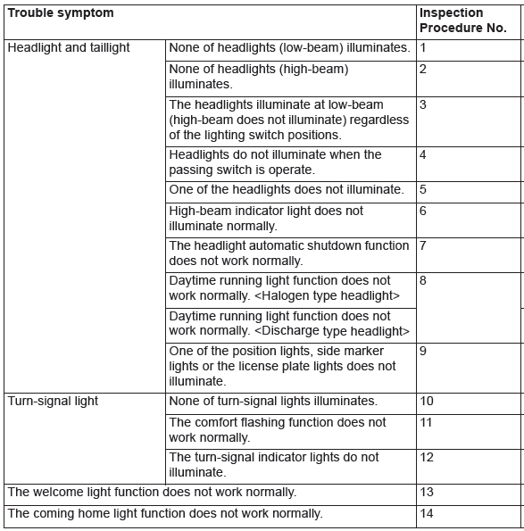
TROUBLE SYMPTOM CHART
READ NEXT:
 Symptom Procedures
Inspection Procedure 1: None of headlights (low-beam) illuminates.
CAUTION
Whenever the ECU is replaced, ensure that the
power supply circuit, the ground circuit and the
communication circuit are norm
On-vehicle Service
HEADLIGHT AIMING
PRE-AIMING INSTRUCTIONS (LOW-BEAM)
1. Inspect for rusted or faulty headlight assemblies.
2. These conditions must be corrected before a satisfactory
adjustment can be made.
3. Insp
Local Interconnect Network (LIN)
General Information
LIN refers to "Local Interconnect Network," which is a
serial multiplex communication protocol* administrated
by LIN consortium. A communication circuit
employing the LIN protocol
SEE MORE:
Differential
DISASSEMBLY AND ASSEMBLY
Disassembly steps
Differential side bearing
Differential side bearing
Differential sub-assembly
Adjusting shim
Required special tools:
MB990810: Side bearing puller
MB991452: Oil seal installer
MD998812: Installer cap
MD998813: Installer-100
MD998823: Installer
Seat belt inspection
● Check the belts for cuts, worn or frayed webbing and for cracked or deformed
metallic parts. Replace the belt assembly if defective.
● A dirty belt should be cleaned with neutral detergent in warm water. After
rinsing in water, let it dry in the shade.
Do not attempt to bleach or
