Mitsubishi Outlander: Local Interconnect Network (LIN)
General Information
LIN refers to "Local Interconnect Network," which is a serial multiplex communication protocol* administrated by LIN consortium. A communication circuit employing the LIN protocol connects each ECU, and switch and sensor data can be shared among ECUs, which enables more reduction in wiring.
NOTE: *: The regulations that have been decided in detail, from software matters such as the necessary transmission rate for communication, the system, data format, and communication timing control method to hardware matters such as the harness type and length and the resistance values.
STRUCTURE
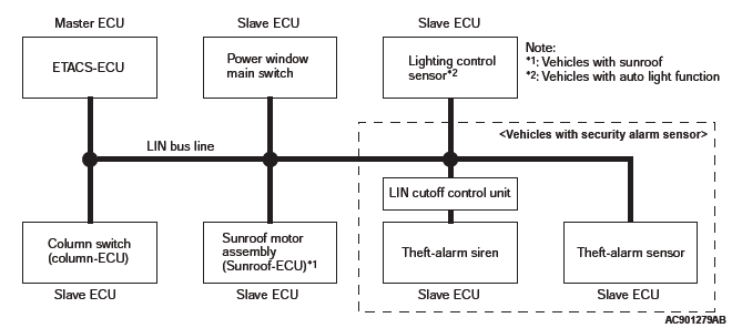
Master and slave ECUs are connected to the LIN bus lines. The master ECU is the ETACS*1-ECU, and the slave ECUs are the column switch (column- ECU), the sunroof motor assembly (sunroof- ECU)*2, the lighting control sensor*3, the power window main switch, the theft-alarm siren (via LIN cutoff control unit*4)*5 and the theft-alarm siren*5.
The master ECU requests these slave ECUs to communicate each other via communication lines.
NOTE:
- *1: ETACS (Electronic Time and Alarm Control System)
- *2: Vehicles with sunroof
- *3: Vehicles with lighting control sensor
- *4: The LIN cutoff control unit is a relay circuit to turn ON/OFF the LIN communication of theft-alarm siren. An ECU is not incorporated in the LIN cutoff control unit.
- *5: Vehicles with theft-alarm sensor
Special Tools
Troubleshooting
DIAGNOSIS FUNCTION
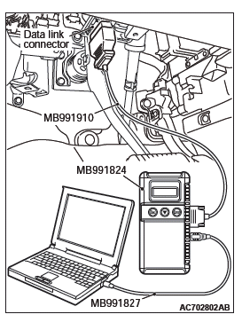
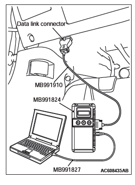
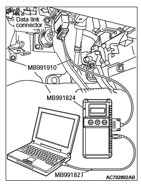
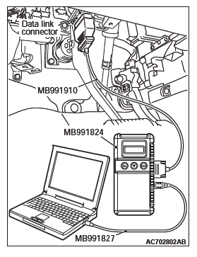
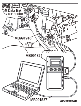
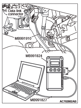
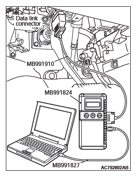
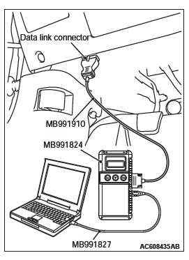
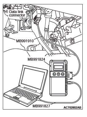
HOW TO CONNECT THE SCAN TOOL (M.U.T.-III)
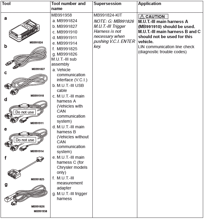
Required Special Tools:
- MB991958: Scan Tool (M.U.T.-III Sub Assembly)
- MB991824: Vehicles Communication Interface (V.C.I.)
- MB991827: M.U.T.-III USB Cable
- MB991910: M.U.T.-III Main Harness A (Vehicles with CAN communication system)
CAUTION To prevent damage to scan tool MB991958, always turn the ignition switch to the "LOCK" (OFF) position before connecting or disconnecting scan tool MB991958.
1. Ensure that the ignition switch is at the "LOCK" (OFF) position.
2. Start up the personal computer.
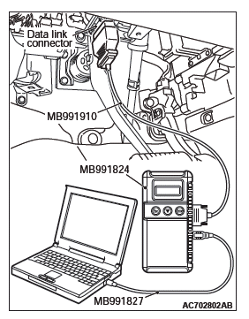
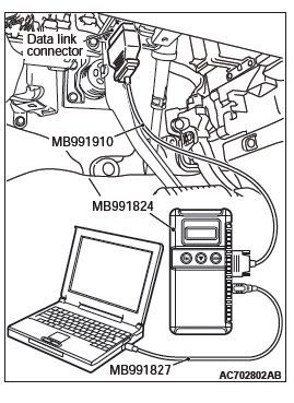
3. Connect special tool MB991827 to special tool MB991824 and the personal computer.
4. Connect special tool MB991910 to special tool MB991824.
5. Connect special tool MB991910 to the data link connector.
6. Turn the power switch of special tool MB991824 to the "ON" position.
NOTE: When special tool MB991824 is energized, special tool MB991824 indicator light will be illuminated in a green color.
7. Start the M.U.T.-III system on the personal computer.
NOTE: Disconnecting scan tool MB991958 is the reverse of the connecting sequence, making sure that the ignition switch is at the "LOCK" (OFF) position.
HOW TO READ AND ERASE DIAGNOSTIC TROUBLE CODES
Required Special Tools:
- MB991958: Scan Tool (M.U.T.-III Sub Assembly)
- MB991824: Vehicles Communication Interface (V.C.I.)
- MB991827: M.U.T.-III USB Cable
- MB991910: M.U.T.-III Main Harness A (Vehicles with CAN communication system)
CAUTION To prevent damage to scan tool MB991958, always turn the ignition switch to the "LOCK" (OFF) position before connecting or disconnecting scan tool MB991958.
NOTE: If the battery voltage is low, diagnostic trouble codes will not be set. Check the battery if scan tool MB991958 does not display.
1. Connect scan tool MB991958 to the data link connector.
2. Turn the ignition switch to the "ON" position.
3. Select "System select" from the start-up screen.
4. Select "From 2006 MY" under "Model Year". Check that "Vehicle Information" contents are correct.
5. Select "ETACS" from "System List", and then press "OK" button.
NOTE: If "Loading Option Setup" list is shown, click appropriate box.
6. Select "Diagnostic Trouble Code" to read the DTC.
7. If a DTC is set, it is shown.
8. Choose "Erase DTCs" to erase the DTC.
DIAGNOSTIC TROUBLE CODE CHART
DIAGNOSTIC TROUBLE CODE PROCEDURES
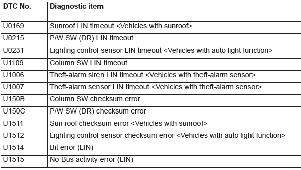
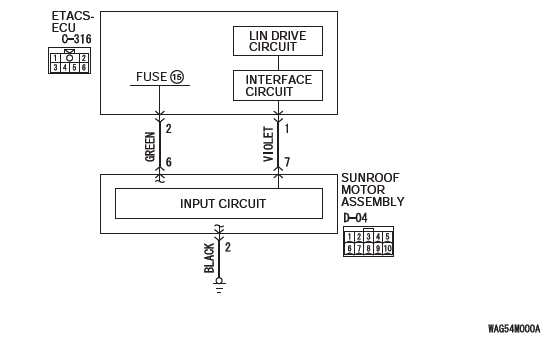
DTC U0169: Sunroof LIN timeout <Vehicles with sunroof>
Sunroof Motor Assembly LIN Communication Circuit
CAUTION Before replacing the ECU, ensure that the communication circuit is normal.
TROUBLE JUDGMENT
The ETACS-ECU receives signal from the sunroof motor assembly (sunroof-ECU). If signal cannot be received at all, DTC U0169 will be set.
TECHNICAL DESCRIPTION (COMMENT)
Current trouble
- Connector(s) or wiring harness in the LIN bus lines between the sunroof motor assembly and the ETACS-ECU, the power supply system of the sunroof motor assembly, or the sunroof motor assembly itself may be defective.
Past trouble
- If DTC U0169 is stored as a past trouble, carry out diagnosis with particular emphasis on wiring and connector(s) in the LIN bus line between the sunroof motor assembly and the ETACS-ECU, and the power supply system of the sunroof motor assembly. For diagnosis procedures, refer to GROUP 00, How to Use Troubleshooting/ Inspection Service Points − How to Treat Past Trouble.
TROUBLESHOOTING HINTS
- The sunroof motor assembly may be defective.
- The wiring harness or connectors may have loose, corroded, or damaged terminals, or terminals pushed back in the connector.
DIAGNOSIS
Required Special Tools:
- MB991958: Scan Tool (M.U.T.-III Sub Assembly)
- MB991824: Vehicles Communication Interface (V.C.I.)
- MB991827: M.U.T.-III USB Cable
- MB991910: M.U.T.-III Main Harness A (Vehicles with CAN communication system)
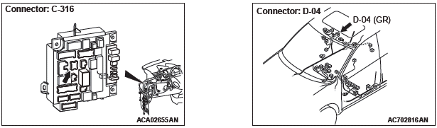
STEP 1. Check ETACS-ECU connector C-316 and sunroof motor assembly connector D-04 for loose, corroded or damaged terminals, or terminals pushed back in the connector.
Q: Are ETACS-ECU connector C-316 and sunroof motor assembly connector D-04 in good condition?
YES : Go to Step 2.
NO : Repair or replace the damaged component(s). Go to Step 7.
STEP 2. Check the ground circuit to the sunroof motor assembly. Measure the resistance at sunroof motor assembly connectors D-04.
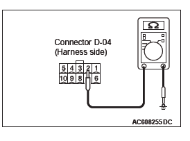
(1) Disconnect sunroof motor assembly connector D-04 and measure the resistance available at the wiring harness side of the connector.
(2) Measure the resistance value between sunroof motor assembly connector D-04 terminal 2 and ground.
- The resistance should be 2 ohms or less.
Q: Is the measured resistance 2 ohms or less?
YES : Go to Step 4.
NO : Go to Step 3.
STEP 3. Check the wiring harness between sunroof motor assembly connector D-04 (terminal 2) and the ground.
- Check the ground wires for open circuit.
Q: Is the wiring harness between sunroof motor assembly connector D-04 (terminal 2) and the ground in good condition?
YES : No action is necessary and testing is complete.
NO : The wiring harness may be damaged or the connector(s) may have loose, corroded or damaged terminals, or terminals pushed back in the connector.
Repair the wiring harness as necessary.
STEP 4. Check the battery power supply circuit to the sunroof motor assembly. Measure the voltage at sunroof motor assembly connector D-04.
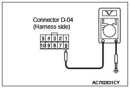
(1) Disconnect sunroof motor assembly connector D-04 measure the voltage available at the wiring harness side of the connector.
(2) Measure the voltage between sunroof motor assembly connector D-04 terminal 6 and ground.
- The voltage should measure approximately 12 volts (battery positive voltage).
Q: Is the measured voltage approximately 12 volts (battery positive voltage)?
YES : Go to Step 6.
NO : Go to Step 5.
STEP 5. Check the wiring harness between ETACS-ECU connector C-316 (terminal 2) and sunroof motor assembly connector D-04 (terminal 6).
- Check the power supply line (battery supply) for open circuit and short circuit.
Q: Is the wiring harness between ETACS-ECU connector C-316 (terminal 2) and sunroof motor assembly connector D-04 (terminal 6) in good condition?
YES : No action is necessary and testing is complete.
NO : The wiring harness may be damaged or the connector(s) may have loose, corroded or damaged terminals, or terminals pushed back in the connector.
Repair the wiring harness as necessary.
STEP 6. Check the wiring harness between ETACS-ECU connector C-316 (terminal 1) and sunroof motor assembly connector D-04 (terminal 7).
- Check the communication line for open circuit.
Q: Is the wiring harness between ETACS-ECU connector C-316 (terminal 1) and sunroof motor assembly connector D-04 (terminal 7) in good condition?
YES : Go to Step 7.
NO : The wiring harness may be damaged or the connector(s) may have loose, corroded or damaged terminals, or terminals pushed back in the connector.
Repair the wiring harness as necessary. Go to Step 7.
STEP 7. Recheck for diagnostic trouble code.
Check again if the DTC is set to the ETACS-ECU.
CAUTION To prevent damage to scan tool MB991958, always turn the ignition switch to the "LOCK" (OFF) position before connecting or disconnecting scan tool MB991958.
(1) Ensure that the ignition switch is at the "LOCK" (OFF) position.
(2) Start up the personal computer.
(3) Connect special tool MB991827 to special tool MB991824 and the personal computer.
(4) Connect special tool MB991910 to special tool MB991824.
(5) Connect special tool MB991910 to the data link connector.
(6) Erase the DTC.
(7) Turn the ignition switch to the "ON" position.
(8) Check if the DTC is set.
(9) Turn the ignition switch to the "LOCK" (OFF) position.
Q: Is the DTC set?
YES : Replace the sunroof motor assembly.
NO : A poor connection, open circuit or other intermittent malfunction is present in the LIN bus lines between the sunroof motor assembly and the ETACS-ECU.
DTC U0215: P/W SW (DR) LIN timeout
Power Window Main Switch LIN Communication Circuit
CAUTION Before replacing the ECU, ensure that the communication circuit is normal.
TROUBLE JUDGMENT
The ETACS-ECU receives signal from the power window main switch. If signal cannot be received at all, DTC U0215 will be set.
TECHNICAL DESCRIPTION (COMMENT)
Current trouble
- Connector(s) or wiring harness in the LIN bus lines between the power window main switch and the ETACS-ECU, the power supply system of the power window main switch, or the power window main switch itself may be defective.
Past trouble
If DTC U0215 is stored as a past trouble, carry out diagnosis with particular emphasis on wiring and connector(s) in the LIN bus line between the power window main switch and the ETACS-ECU, and the power supply system of the power window main switch. For diagnosis procedures, refer to GROUP 00, How to Use Troubleshooting/ Inspection Service Points − How to Treat Past Trouble.
TROUBLESHOOTING HINTS
- The power window main switch may be defective.
- The wiring harness or connectors may have loose, corroded, or damaged terminals, or terminals pushed back in the connector.
DIAGNOSIS
Required Special Tools:
- MB991958: Scan Tool (M.U.T.-III Sub Assembly)
- MB991824: Vehicles Communication Interface (V.C.I.)
- MB991827: M.U.T.-III USB Cable
- MB991910: M.U.T.-III Main Harness A (Vehicles with CAN communication system)
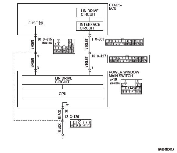
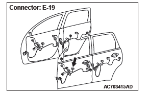
STEP 1. Check ETACS-ECU connectors C-301 and C-315 and power window main switch connector E-19 for loose, corroded or damaged terminals, or terminals pushed back in the connector.
Q: Are ETACS-ECU connectors C-301 and C-315 and power window main switch connector E-19 in good condition?
YES : Go to Step 2.
NO : Repair or replace the damaged component(s). Go to Step 7.
STEP 2. Check the ground circuit to the power window main switch. Measure the resistance at power window main switch connector E-19.
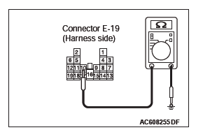
(1) Disconnect power window main switch connector E-19 and measure the resistance available at the wiring harness side of the connector.
(2) Measure the resistance value between power window main switch connector E-19 terminal 10 and ground.
- The resistance should be 2 ohms or less.
Q: Is the measured resistance 2 ohms or less?
YES : Go to Step 4.
NO : Go to Step 3.
STEP 3. Check the wiring harness between power window main switch connector E-19 (terminal 10) and the ground.
- Check the ground wires for open circuit.
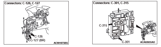
NOTE: Also check intermediate connector C-126 for loose, corroded, or damaged terminals, or terminals pushed back in the connector. If intermediate connector C-126 is damaged, repair or replace the connector as described in GROUP 00E, Harness Connector Inspection.
Q: Is the wiring harness between power window main switch connector E-19 (terminal 10) and the ground in good condition?
YES : No action is necessary and testing is complete.
NO : The wiring harness may be damaged or the connector(s) may have loose, corroded or damaged terminals, or terminals pushed back in the connector.
Repair the wiring harness as necessary.
STEP 4. Check the battery power supply circuit to the power window main switch. Measure the voltage at power window main switch connector E-19.
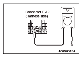
(1) Disconnect power window main switch connector E-19 measure the voltage available at the wiring harness side of the connector.
(2) Measure the voltage between power window main switch connector E-19 terminal 10 and ground.
- The voltage should measure approximately 12 volts (battery positive voltage).
Q: Is the measured voltage approximately 12 volts (battery positive voltage)?
YES : Go to Step 6.
NO : Go to Step 5.
STEP 5. Check the wiring harness between ETACS-ECU connector C-315 (terminal 10) and power window main switch connector E-19 (terminal 5).
- Check the power supply line (battery supply) for open circuit and short circuit.
NOTE: Also check intermediate connector C-126 for loose, corroded, or damaged terminals, or terminals pushed back in the connector. If intermediate connector C-126 is damaged, repair or replace the connector as described in GROUP 00E, Harness Connector Inspection.
Q: Is the wiring harness between ETACS-ECU connector C-315 (terminal 10) and power window main switch connector E-19 (terminal 5) in good condition?
YES : No action is necessary and testing is complete.
NO : The wiring harness may be damaged or the connector(s) may have loose, corroded or damaged terminals, or terminals pushed back in the connector.
Repair the wiring harness as necessary.
STEP 6. Check the wiring harness between ETACS-ECU connector C-301 (terminal 1) and power window main switch connector E-19 (terminal 7).
- Check the communication line for open circuit.
NOTE: Also check intermediate connector C-127 for loose, corroded, or damaged terminals, or terminals pushed back in the connector. If intermediate connector C-127 is damaged, repair or replace the connector as described in GROUP 00E, Harness Connector Inspection.
Q: Is the wiring harness between ETACS-ECU connector C-301 (terminal 1) and power window main switch connector E-19 (terminal 7) in good condition?
YES : Go to Step 7.
NO : The wiring harness may be damaged or the connector(s) may have loose, corroded or damaged terminals, or terminals pushed back in the connector.
Repair the wiring harness as necessary. Go to Step 7.
STEP 7. Recheck for diagnostic trouble code.
Check again if the DTC is set to the ETACS-ECU.
CAUTION To prevent damage to scan tool MB991958, always turn the ignition switch to the "LOCK" (OFF) position before connecting or disconnecting scan tool MB991958.
(1) Ensure that the ignition switch is at the "LOCK" (OFF) position.
(2) Start up the personal computer.
(3) Connect special tool MB991827 to special tool MB991824 and the personal computer.
(4) Connect special tool MB991910 to special tool MB991824.
(5) Connect special tool MB991910 to the data link connector.
(6) Erase the DTC.
(7) Turn the ignition switch to the "ON" position.
(8) Check if the DTC is set.
(9) Turn the ignition switch to the "LOCK" (OFF) position.
Q: Is the DTC set?
YES : Replace the power window main switch.
NO : A poor connection, open circuit or other intermittent malfunction is present in the LIN bus lines between the power window main switch and the ETACS-ECU.
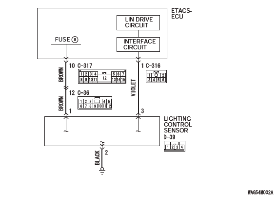
DTC U0231: Lighting control sensor LIN timeout <Vehicles with auto light function>
CAUTION Before replacing the ECU, ensure that the communication circuit is normal.
Lighting Control Sensor LIN Communication Circuit
TROUBLE JUDGMENT
The ETACS-ECU receives signal from the lighting control sensor. If signal cannot be received at all, DTC U0231 will be set.
TECHNICAL DESCRIPTION (COMMENT)
Current trouble
- Connector(s) or wiring harness in the LIN bus lines between the lighting control sensor and the ETACS-ECU, the power supply system of the lighting control sensor, or the lighting control sensor itself may be defective.
Past trouble
- If DTC U0169 is stored as a past trouble, carry out diagnosis with particular emphasis on wiring and connector(s) in the LIN bus line between the lighting control sensor and the ETACS-ECU, and the power supply system of the lighting control sensor.
TROUBLESHOOTING HINTS
- The lighting control sensor may be defective.
- The wiring harness or connectors may have loose, corroded, or damaged terminals, or terminals pushed back in the connector.
DIAGNOSIS
Required Special Tools:
- MB991958: Scan Tool (M.U.T.-III Sub Assembly)
- MB991824: Vehicles Communication Interface (V.C.I.)
- MB991827: M.U.T.-III USB Cable
- MB991910: M.U.T.-III Main Harness A (Vehicles with CAN communication system)
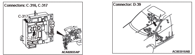
STEP 1. Check ETACS-ECU connectors C-316 and C-317 and lighting control sensor connector D-39 for loose, corroded or damaged terminals, or terminals pushed back in the connector.
Q: Are ETACS-ECU connectors C-316 and C-317 and lighting control sensor connector D-39 in good condition?
YES : Go to Step 2.
NO : Repair or replace the damaged component(s). Go to Step 7.
STEP 2. Check the ground circuit to the lighting control sensor. Measure the resistance at lighting control sensor connector D-39.
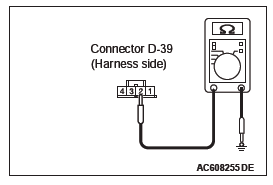
(1) Disconnect power window main switch connector D-39 and measure the resistance available at the wiring harness side of the connector.
(2) Measure the resistance value between power window main switch connector D-39 terminal 2 and ground.
- The resistance should be 2 ohms or less.
Q: Is the measured resistance 2 ohms or less?
YES : Go to Step 4.
NO : Go to Step 3.
STEP 3. Check the wiring harness between lighting control sensor connector D-39 (terminal 2) and the ground.
- Check the ground wires for open circuit.
Q: Is the wiring harness between lighting control sensor connector D-39 (terminal 2) and the ground in good condition?
YES : No action is necessary and testing is complete.
NO : The wiring harness may be damaged or the connector(s) may have loose, corroded or damaged terminals, or terminals pushed back in the connector.
Repair the wiring harness as necessary.
STEP 4. Check the battery power supply circuit to the lighting control sensor. Measure the voltage at lighting control sensor connector D-39.
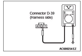
(1) Disconnect lighting control sensor connector D-39 measure the voltage available at the wiring harness side of the connector.
(2) Measure the voltage between lighting control sensor connector D-39 terminal 2 and ground.
- The voltage should measure approximately 12 volts (battery positive voltage).
Q: Is the measured voltage approximately 12 volts (battery positive voltage)?
YES : Go to Step 6.
NO : Go to Step 5.
STEP 5. Check the wiring harness between ETACS-ECU connector C-317 (terminal 10) and lighting control sensor connector D-39 (terminal 1).
- Check the power supply line (battery supply) for open circuit and short circuit.
Q: Is the wiring harness between ETACS-ECU connector C-317 (terminal 10) and lighting control sensor connector D-39 (terminal 1) in good condition?
YES : No action is necessary and testing is complete.
NO : The wiring harness may be damaged or the connector(s) may have loose, corroded or damaged terminals, or terminals pushed back in the connector.
Repair the wiring harness as necessary.
STEP 6. Check the wiring harness between ETACS-ECU connector C-316 (terminal 1) and lighting control sensor connector D-39 (terminal 3).
- Check the communication line for open circuit.
Q: Is the wiring harness between ETACS-ECU connector C-316 (terminal 1) and lighting control sensor connector D-39 (terminal 3) in good condition?
YES : Go to Step 7.
NO : The wiring harness may be damaged or the connector(s) may have loose, corroded or damaged terminals, or terminals pushed back in the connector.
Repair the wiring harness as necessary. Go to Step 7.
STEP 7. Recheck for diagnostic trouble code.
Check again if the DTC is set to the ETACS-ECU.
CAUTION To prevent damage to scan tool MB991958, always turn the ignition switch to the "LOCK" (OFF) position before connecting or disconnecting scan tool MB991958.
(1) Connect scan tool MB991958. Refer to "How to connect the Scan Tool (M.U.T.-III)".
(2) Erase the DTC.
(3) Turn the ignition switch to the "ON" position.
(4) Check if the DTC is set.
(5) Turn the ignition switch to the "LOCK" (OFF) position.
Q: Is the DTC set?
YES : Replace the lighting control sensor.
NO : A poor connection, open circuit or other intermittent malfunction is present in the LIN bus lines between the lighting control sensor and the ETACS-ECU.
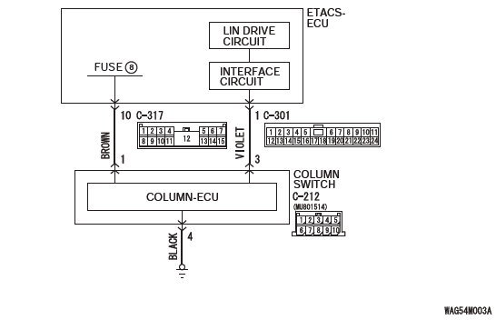
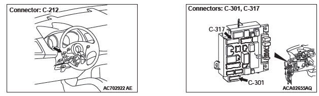
DTC U1109: Column SW LIN timeout
Column Switch LIN Communication Circuit
CAUTION Before replacing the ECU, ensure that the communication circuit is normal.
TROUBLE JUDGMENT
The ETACS-ECU receives signal from the column switch. If signal cannot be received at all, DTC U1109 will be set.
TECHNICAL DESCRIPTION (COMMENT)
Current trouble
Connector(s) or wiring harness in the LIN bus lines between the column switch and the ETACS-ECU, the power supply system of the column switch, or the column switch itself may be defective.
Past trouble
- If DTC U1109 is stored as a past trouble, carry out diagnosis with particular emphasis on wiring and connector(s) in the LIN bus line between the column switch and the ETACS-ECU, and the power supply system of the column switch. For diagnosis procedures, refer to GROUP 00, How to Use Troubleshooting/Inspection Service Points − How to Treat Past Trouble.
TROUBLESHOOTING HINTS
- The column switch may be defective.
- The wiring harness or connectors may have loose, corroded, or damaged terminals, or terminals pushed back in the connector.
DIAGNOSIS
Required Special Tools:
- MB991958: Scan Tool (M.U.T.-III Sub Assembly)
- MB991824: Vehicles Communication Interface (V.C.I.)
- MB991827: M.U.T.-III USB Cable
- MB991910: M.U.T.-III Main Harness A (Vehicles with CAN communication system)
STEP 1. Check ETACS-ECU connectors C-301 and C-317 and column switch connector C-212 for loose, corroded or damaged terminals, or terminals pushed back in the connector.
Q: Are ETACS-ECU connectors C-301 and C-317 and column switch connector C-212 in good condition?
YES : Go to Step 2.
NO : Repair or replace the damaged component(s). Go to Step 7.
STEP 2. Check the ground circuit to the column switch.
Measure the resistance at column switch connector C-212.
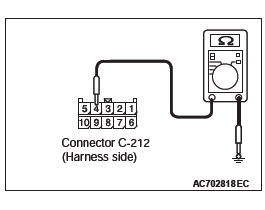
(1) Disconnect column switch connector C-212 and measure the resistance available at the wiring harness side of the connector.
(2) Measure the resistance value between column switch connector C-212 terminal 4 and ground.
- The resistance should be 2 ohms or less.
Q: Is the measured resistance 2 ohms or less?
YES : Go to Step 4.
NO : Go to Step 3.
STEP 3. Check the wiring harness between column switch connector C-212 (terminal 4) and the ground.
- Check the ground wires for open circuit.
Q: Is the wiring harness between column switch connector C-212 (terminal 4) and the ground in good condition?
YES : No action is necessary and testing is complete.
NO : The wiring harness may be damaged or the connector(s) may have loose, corroded or damaged terminals, or terminals pushed back in the connector.
Repair the wiring harness as necessary.
STEP 4. Check the battery power supply circuit to the column switch. Measure the voltage at column switch connector C-212.
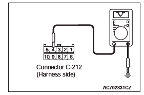
(1) Disconnect column switch connector C-212 measure the voltage available at the wiring harness side of the connector.
(2) Measure the voltage between column switch connector C-212 terminal 4 and ground.
- The voltage should measure approximately 12 volts (battery positive voltage).
Q: Is the measured voltage approximately 12 volts (battery positive voltage)?
YES : Go to Step 6.
NO : Go to Step 5.
STEP 5. Check the wiring harness between ETACS-ECU connector C-317 (terminal 10) and column switch connector C-212 (terminal 1).
- Check the power supply line (battery supply) for open circuit and short circuit.
Q: Is the wiring harness between ETACS-ECU connector C-317 (terminal 10) and column switch connector C-212 (terminal 1) in good condition?
YES : No action is necessary and testing is complete.
NO : The wiring harness may be damaged or the connector(s) may have loose, corroded or damaged terminals, or terminals pushed back in the connector.
Repair the wiring harness as necessary.
STEP 6. Check the wiring harness between ETACS-ECU connector C-301 (terminal 1) and column switch connector C-212 (terminal 3).
- Check the communication line for open circuit.
Q: Is the wiring harness between ETACS-ECU connector C-301 (terminal 1) and column switch connector C-212 (terminal 3) in good condition?
YES : Go to Step 7.
NO : The wiring harness may be damaged or the connector(s) may have loose, corroded or damaged terminals, or terminals pushed back in the connector.
Repair the wiring harness as necessary. Go to Step 7.
STEP 7. Recheck for diagnostic trouble code.
Check again if the DTC is set to the ETACS-ECU.
CAUTION To prevent damage to scan tool MB991958, always turn the ignition switch to the "LOCK" (OFF) position before connecting or disconnecting scan tool MB991958.
(1) Ensure that the ignition switch is at the "LOCK" (OFF) position.
(2) Start up the personal computer.
(3) Connect special tool MB991827 to special tool MB991824 and the personal computer.
(4) Connect special tool MB991910 to special tool MB991824.
(5) Connect special tool MB991910 to the data link connector.
(6) Erase the DTC.
(7) Turn the ignition switch to the "ON" position.
(8) Check if the DTC is set.
(9) Turn the ignition switch to the "LOCK" (OFF) position.
Q: Is the DTC set?
YES : Replace the lighting switch.
NO : A poor connection, open circuit or other intermittent malfunction is present in the LIN bus lines between the column switch and the ETACS-ECU.
Code No.U1006 Theft-alarm siren LIN timeout <Vehicles with theft-alarm sensor>
CAUTION Before replacing the ECU, ensure that the communication circuit is normal.
Theft-Alarm Siren LIN Communication Circuit
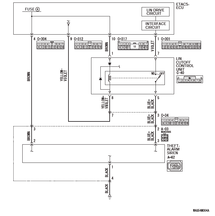
TROUBLE JUDGMENT
The ETACS-ECU receives signal from the theft-alarm siren. If signal cannot be received at all, DTC U1006 will be set.
TECHNICAL DESCRIPTION (COMMENT)
Current trouble
- Connector(s) or wiring harness in the LIN bus lines between the theft-alarm siren and the ETACS-ECU, the power supply system of the power window main switch, or the theft-alarm siren itself may be defective.
Past trouble
- If DTC U1006 is stored as a past trouble, carry out diagnosis with particular emphasis on wiring and connector(s) in the LIN bus line between the theft-alarm siren and the ETACS-ECU, and the power supply system of the theft-alarm siren. For diagnosis procedures, refer to GROUP 00, How to Use Troubleshooting/Inspection Service Points − How to Treat Past Trouble.
TROUBLESHOOTING HINTS
- The theft-alarm siren may be defective.
- The LIN cutoff control unit may be defective.
- The wiring harness or connectors may have loose, corroded, or damaged terminals, or terminals pushed back in the connector.
DIAGNOSIS PROCEDURE
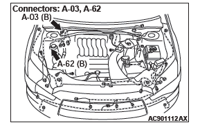
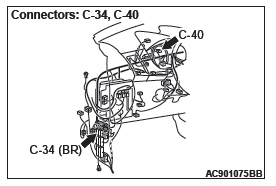
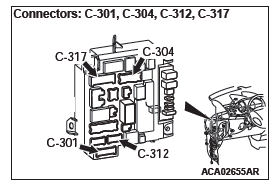
STEP 1. Check ETACS-ECU connectors C-301, C-304, C-312 and C-317, LIN cutoff control unit connector C-40, theft-alarm siren connector A-62 for loose, corroded or damaged terminals, or terminals pushed back in the connector.
Q: Are ETACS-ECU connectors C-301, C-304, C-312 and C-317, LIN cutoff control unit connector C-40, theft-alarm siren connector A-62 in good condition?
YES : Go to Step 2.
NO : Repair or replace the damaged component(s). Go to Step 12.
STEP 2. Check the ground circuit to the theft-alarm siren.
Measure the resistance at theft-alarm siren connector A-62.
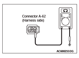
(1) Disconnect theft-alarm siren connector A-62 and measure the resistance available at the wiring harness side of the connector.
(2) Measure the resistance value between theft-alarm siren connector A-62 terminal 1 and ground.
- The resistance should be 2 or less.
Q: Is the measured resistance 2 or less?
YES : Go to Step 4.
NO : Go to Step 3.
STEP 3. Check the wiring harness between theft-alarm siren connector A-62 (terminal 1) and the ground.
Check the ground wires for open circuit.
NOTE: Also check intermediate connector A-03 for loose, corroded, or damaged terminals, or terminals pushed back in the connector. If intermediate connector A-03 is damaged, repair or replace the connector as described in GROUP 00E, Harness Connector Inspection.
Q: Is the wiring harness between theft-alarm siren connector A-62 (terminal 1) and the ground in good condition?
YES : No action is necessary and testing is complete.
NO : The wiring harness may be damaged or the connector(s) may have loose, corroded or damaged terminals, or terminals pushed back in the connector.
Repair the wiring harness as necessary.
STEP 4. Check the battery power supply circuit to the theft-alarm siren. Measure the voltage at theft-alarm siren connector A-62.
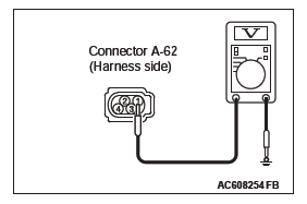
(1) Disconnect theft-alarm siren connector A-62 measure the voltage available at the wiring harness side of the connector.
(2) Measure the voltage between theft-alarm siren connector A-62 terminal 1 and ground.
- The voltage should measure approximately 12 volts (battery positive voltage).
Q: Is the measured voltage approximately 12 volts (battery positive voltage)?
YES : Go to Step 6.
NO : Go to Step 5.
STEP 5. Check the wiring harness between ETACS-ECU connector C-304 (terminal 4) and theft-alarm siren connector A-62 (terminal 2).
- Check the power supply line (battery supply) for open circuit and short circuit.
NOTE: Also check intermediate connector A-03 for loose, corroded, or damaged terminals, or terminals pushed back in the connector. If intermediate connector A-03 is damaged, repair or replace the connector as described in GROUP 00E, Harness Connector Inspection.
Q: Is the wiring harness between ETACS-ECU connector C-304 (terminal 4) and theft-alarm siren connector A-62 (terminal 2) in good condition?
YES : No action is necessary and testing is complete.
NO : The wiring harness may be damaged or the connector(s) may have loose, corroded or damaged terminals, or terminals pushed back in the connector.
Repair the wiring harness as necessary.
STEP 6. Check the LIN cutoff control unit.
Remove the LIN cutoff control unit. Check for continuity between the following terminals and inspect the relay.
- Continuity check
- Relay check
Q: Is the LIN cutoff control unit in good condition?
YES : Go to Step 7.
NO : Replace the LIN cutoff control unit.
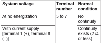
STEP 7. Check the battery power supply circuit to the ETACS-ECU. Measure the voltage at ETACS-ECU connector C-312.
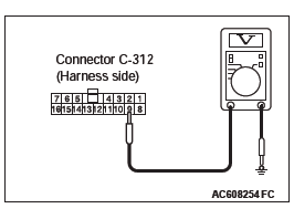
(1) Disconnect ETACS-ECU connector C-312 measure the voltage available at the wiring harness side of the connector.
(2) Measure the voltage between ETACS-ECU connector C-312 terminal 9 and ground.
- The voltage should measure approximately 12 volts (battery positive voltage).
Q: Is the check result normal?
YES : Go to Step 10.
NO : Go to Step 8.
STEP 8. Check the wiring harness between ETACS-ECU connector C-317 (terminal 10) and LIN cutoff control unit connector C-40 (terminal 1).
- Check the power supply line (battery supply) for open circuit and short circuit.
Q: Is the wiring harness between ETACS-ECU connector C-317 (terminal 10) and LIN cutoff control unit connector C-40 (terminal 1) in good condition?
YES : Go to Step 9.
NO : The wiring harness may be damaged or the connector(s) may have loose, corroded or damaged terminals, or terminals pushed back in the connector.
Repair the wiring harness as necessary.
STEP 9. Check the wiring harness between ETACS-ECU connector C-312 (terminal 9) and LIN cutoff control unit connector C-40 (terminal 8).
- Check the power supply line (battery supply) for open circuit and short circuit.
NOTE: Also check intermediate connector C-34 for loose, corroded, or damaged terminals, or terminals pushed back in the connector. If intermediate connector C-34 is damaged, repair or replace the connector as described in GROUP 00E, Harness Connector Inspection.
Q: Is the wiring harness between ETACS-ECU connector C-312 (terminal 9) and LIN cutoff control unit connector C-40 (terminal 8) in good condition?
YES : Go to Step 12.
NO : The wiring harness may be damaged or the connector(s) may have loose, corroded or damaged terminals, or terminals pushed back in the connector.
Repair the wiring harness as necessary.
STEP 10. Check the wiring harness between ETACS-ECU connector C-301 (terminal 1) and LIN cutoff control unit connector C-40 (terminal 7).
- Check the communication line for open circuit.
Q: Is the wiring harness between ETACS-ECU connector C-301 (terminal 1) and LIN cutoff control unit connector C-40 (terminal 7) in good condition?
YES : Go to Step 11.
NO : The wiring harness may be damaged or the connector(s) may have loose, corroded or damaged terminals, or terminals pushed back in the connector.
Repair the wiring harness as necessary.
STEP 11. Check the wiring harness between LIN cutoff control unit connector C-40 (terminal 5) and theft-alarm siren connector A-62 (terminal 3).
- Check the communication line for open circuit.
NOTE: Also check intermediate connectors A-03 and C-34 for loose, corroded, or damaged terminals, or terminals pushed back in the connector. If intermediate connectors A-03 and C-34 is damaged, repair or replace the connector as described in GROUP 00E, Harness Connector Inspection.
Q: Is the wiring harness between LIN cutoff control unit connector C-40 (terminal 5) and theft-alarm siren connector A-62 (terminal 3) in good condition?
YES : Go to Step 12.
NO : The wiring harness may be damaged or the connector(s) may have loose, corroded or damaged terminals, or terminals pushed back in the connector.
Repair the wiring harness as necessary.
STEP 12. Recheck for diagnostic trouble code.
Check again if the DTC is set to the ETACS-ECU.
CAUTION To prevent damage to scan tool MB991958, always turn the ignition switch to the "LOCK" (OFF) position before connecting or disconnecting scan tool MB991958.

(1) Ensure that the ignition switch is at the "LOCK" (OFF) position.
(2) Start up the personal computer.
(3) Connect special tool MB991827 to special tool MB991824 and the personal computer.
(4) Connect special tool MB991910 to special tool MB991824.
(5) Connect special tool MB991910 to the data link connector.
(6) Erase the DTC.
(7) Turn the ignition switch to the "ON" position.
(8) Check if the DTC is set.
(9) Turn the ignition switch to the "LOCK" (OFF) position.
Q: Is the DTC set?
YES : Replace the security alarm siren.
NO : A poor connection, open circuit or other intermittent malfunction is present in the LIN bus lines between the power window main switch and the ETACS-ECU.
Code No.U1007 Theft-alarm sensor LIN timeout <Vehicles with theft-alarm sensor>
CAUTION Before replacing the ECU, ensure that the communication circuit is normal.
Theft-Alarm Sensor LIN Communication Circuit

TROUBLE JUDGMENT
The ETACS-ECU receives signal from the theft-alarm sensor. If signal cannot be received at all, DTC U1007 will be set.
TECHNICAL DESCRIPTION (COMMENT)
Current trouble
- Connector(s) or wiring harness in the LIN bus lines between the theft-alarm sensor and the ETACS-ECU, the power supply system of the power window main switch, or the theft-alarm sensor itself may be defective.
Past trouble
- If DTC U1007 is stored as a past trouble, carry
out diagnosis with particular emphasis on wiring
and connector(s) in the LIN bus line between the
theft-alarm sensor and the ETACS-ECU, and the
power supply system of the theft-alarm sensor.
For diagnosis procedures, refer to GROUP 00, How to Use Troubleshooting/Inspection Service Points − How to Treat Past Trouble.
TROUBLESHOOTING HINTS
- The theft-alarm sensor may be defective.
- The wiring harness or connectors may have loose, corroded, or damaged terminals, or terminals pushed back in the connector.
DIAGNOSIS PROCEDURE
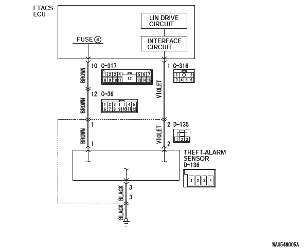
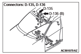
STEP 1. Check ETACS-ECU connectors C-316 and C-317 and theft-alarm sensor connector D-136 for loose, corroded or damaged terminals, or terminals pushed back in the connector.
Q: Are ETACS-ECU connectors C-316 and C-317 and theft-alarm sensor connector D-136 in good condition?
YES : Go to Step 2.
NO : Repair or replace the damaged component(s). Go to Step 7.
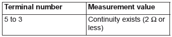
STEP 2. Check the ground circuit to the theft-alarm sensor.
Measure the resistance at theft-alarm sensor connector D-136.
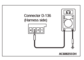
(1) Disconnect theft-alarm sensor connector D-136 and measure the resistance available at the wiring harness side of the connector.
(2) Measure the resistance value between theft-alarm sensor connector D-136 terminal 3 and ground.
- The resistance should be 2 ohms or less.
Q: Is the measured resistance 2 ohms or less?
YES : Go to Step 4.
NO : Go to Step 3.
STEP 3. Check the wiring harness between theft-alarm sensor connector D-136 (terminal 3) and the ground.
- Check the ground wires for open circuit.
NOTE: Also check intermediate connector D-135 for loose, corroded, or damaged terminals, or terminals pushed back in the connector. If intermediate connector D-135 is damaged, repair or replace the connector as described in GROUP 00E, Harness Connector Inspection.
Q: Is the wiring harness between theft-alarm sensor connector D-136 (terminal 3) and the ground in good condition?
YES : No action is necessary and testing is complete.
NO : The wiring harness may be damaged or the connector(s) may have loose, corroded or damaged terminals, or terminals pushed back in the connector.
Repair the wiring harness as necessary.
STEP 4. Check the battery theft-alarm sensor. Measure the voltage at theft-alarm sensor connector D-136.
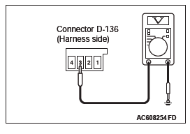
(1) Disconnect theft-alarm sensor connector D-136 measure the voltage available at the wiring harness side of the connector.
(2) Measure the voltage between theft-alarm sensor connector D-136 terminal 3 and ground.
- The voltage should measure approximately 12 volts (battery positive voltage).
Q: Is the measured voltage approximately 12 volts (battery positive voltage)?
YES : Go to Step 6.
NO : Go to Step 5.
STEP 5. Check the wiring harness between ETACS-ECU connector C-317 (terminal 10) and theft-alarm sensor connector D-136 (terminal 1).
- Check the power supply line (battery supply) for open circuit and short circuit.
NOTE: Also check intermediate connector C-36 and D-135 for loose, corroded, or damaged terminals, or terminals pushed back in the connector. If intermediate connector C-36 and D-135 is damaged, repair or replace the connector as described in GROUP 00E, Harness Connector Inspection.
Q: Is the wiring harness between ETACS-ECU connector C-317 (terminal 10) and theft-alarm sensor connector D134 (terminal 1) in good condition?
YES : No action is necessary and testing is complete.
NO : The wiring harness may be damaged or the connector(s) may have loose, corroded or damaged terminals, or terminals pushed back in the connector.
Repair the wiring harness as necessary.
STEP 6. Check the wiring harness between ETACS-ECU connector C-316 (terminal 1) and theft-alarm sensor connector D-136 (terminal 2).
- Check the communication line for open circuit.
NOTE: Also check intermediate connector D-135 for loose, corroded, or damaged terminals, or terminals pushed back in the connector. If intermediate connector D-135 is damaged, repair or replace the connector as described in GROUP 00E, Harness Connector Inspection.
Q: Is the wiring harness between ETACS-ECU connector C-316 (terminal 1) and theft-alarm sensor connector D-136 (terminal 2) in good condition?
YES : Go to Step 7.
NO : The wiring harness may be damaged or the connector(s) may have loose, corroded or damaged terminals, or terminals pushed back in the connector.
Repair the wiring harness as necessary.
STEP 7. Recheck for diagnostic trouble code.
Check again if the DTC is set to the ETACS-ECU.
CAUTION To prevent damage to scan tool MB991958, always turn the ignition switch to the "LOCK" (OFF) position before connecting or disconnecting scan tool MB991958.
(1) Ensure that the ignition switch is at the "LOCK" (OFF) position.
(2) Start up the personal computer.
(3) Connect special tool MB991827 to special tool MB991824 and the personal computer.
(4) Connect special tool MB991910 to special tool MB991824.
(5) Connect special tool MB991910 to the data link connector.
(6) Erase the DTC.
(7) Turn the ignition switch to the "ON" position.
(8) Check if the DTC is set.
(9) Turn the ignition switch to the "LOCK" (OFF) position.
Q: Is the DTC set?
YES : Replace the power window main switch.
NO : A poor connection, open circuit or other intermittent malfunction is present in the LIN bus lines between the power window main switch and the ETACS-ECU.
DTC U150B: Column SW checksum error
TROUBLE JUDGMENT
The ETACS-ECU will set DTC U150B when abnormal signals are received from the column switch (column- ECU).
TROUBLESHOOTING HINTS
- The column switch (lighting switch) may be defective.
DIAGNOSIS
Required Special Tools:
- MB991958: Scan Tool (M.U.T.-III Sub Assembly)
- MB991824: Vehicles Communication Interface (V.C.I.)
- MB991827: M.U.T.-III USB Cable
- MB991910: M.U.T.-III Main Harness A (Vehicles with CAN communication system)
Recheck for diagnostic trouble code.
Check again if the DTC is set to the ETACS-ECU.
CAUTION To prevent damage to scan tool MB991958, always turn the ignition switch to the "LOCK" (OFF) position before connecting or disconnecting scan tool MB991958.
(1) Ensure that the ignition switch is at the "LOCK" (OFF) position.
(2) Start up the personal computer.
(3) Connect special tool MB991827 to special tool MB991824 and the personal computer.
(4) Connect special tool MB991910 to special tool MB991824.
(5) Connect special tool MB991910 to the data link connector.
(6) Erase the DTC.
(7) Turn the ignition switch to the "ON" position.
(8) Check if the DTC is set.
(9) Turn the ignition switch to the "LOCK" (OFF) position.
Q: Is the DTC set?
YES : Replace the lighting switch.
NO : A poor connection, open circuit, or other intermittent malfunctions in the LIN bus lines between the column switch and the ETACS-ECU.
DTC U150C: P/W SW (DR) checksum error
TROUBLE JUDGMENT
The ETACS-ECU will set DTC U150C when abnormal signals are received from the power window main switch.
TROUBLESHOOTING HINTS
- The power window main switch may be defective.
DIAGNOSIS
Required Special Tools:
- MB991958: Scan Tool (M.U.T.-III Sub Assembly)
- MB991824: Vehicles Communication Interface (V.C.I.)
- MB991827: M.U.T.-III USB Cable
- MB991910: M.U.T.-III Main Harness A (Vehicles with CAN communication system)
Recheck for diagnostic trouble code.
Check again if the DTC is set to the ETACS-ECU.
CAUTION To prevent damage to scan tool MB991958, always turn the ignition switch to the "LOCK" (OFF) position before connecting or disconnecting scan tool MB991958.
(1) Ensure that the ignition switch is at the "LOCK" (OFF) position.
(2) Start up the personal computer.
(3) Connect special tool MB991827 to special tool MB991824 and the personal computer.
(4) Connect special tool MB991910 to special tool MB991824.
(5) Connect special tool MB991910 to the data link connector.
(6) Erase the DTC.
(7) Turn the ignition switch to the "ON" position.
(8) Check if the DTC is set.
(9) Turn the ignition switch to the "LOCK" (OFF) position.
Q: Is the DTC set?
YES : Replace the power window main switch.
NO : A poor connection, open circuit, or other intermittent malfunctions in the LIN bus lines between the power window main switch and the ETACS-ECU.
DTC U1511: Sun roof checksum error <Vehicles with sunroof>
TROUBLE JUDGMENT
The ETACS-ECU will set DTC U1511 when abnormal signals are received from the sunroof motor assembly (sunroof-ECU).
TROUBLESHOOTING HINTS
- The sunroof motor assembly may be defective.
DIAGNOSIS
Required Special Tools:
- MB991958: Scan Tool (M.U.T.-III Sub Assembly)
- MB991824: Vehicles Communication Interface (V.C.I.)
- MB991827: M.U.T.-III USB Cable
- MB991910: M.U.T.-III Main Harness A (Vehicles with CAN communication system)
Recheck for diagnostic trouble code.
Check again if the DTC is set to the ETACS-ECU.
CAUTION To prevent damage to scan tool MB991958, always turn the ignition switch to the "LOCK" (OFF) position before connecting or disconnecting scan tool MB991958.
(1) Ensure that the ignition switch is at the "LOCK" (OFF) position.
(2) Start up the personal computer.
(3) Connect special tool MB991827 to special tool MB991824 and the personal computer.
(4) Connect special tool MB991910 to special tool MB991824.
(5) Connect special tool MB991910 to the data link connector.
(6) Erase the DTC.
(7) Turn the ignition switch to the "ON" position.
(8) Check if the DTC is set.
(9) Turn the ignition switch to the "LOCK" (OFF) position.
Q: Is the DTC set?
YES : Replace the sunroof motor assembly.
NO : A poor connection, open circuit, or other intermittent malfunctions in the LIN bus lines between the sunroof motor assembly and the ETACS-ECU.
DTC U1512: Lighting control sensor checksum error <Vehicles with auto light function>
TROUBLE JUDGMENT
The ETACS-ECU will set DTC U1512 when abnormal signals are received from the lighting control sensor.
TROUBLESHOOTING HINTS
- The lighting control sensor may be defective.
DIAGNOSIS
Required Special Tools:
- MB991958: Scan Tool (M.U.T.-III Sub Assembly)
- MB991824: Vehicles Communication Interface (V.C.I.)
- MB991827: M.U.T.-III USB Cable
- MB991910: M.U.T.-III Main Harness A (Vehicles with CAN communication system)
Recheck for diagnostic trouble code.
Check again if the DTC is set to the ETACS-ECU.
CAUTION To prevent damage to scan tool MB991958, always turn the ignition switch to the "LOCK" (OFF) position before connecting or disconnecting scan tool MB991958.
(1) Connect scan tool MB991958. Refer to "How to connect the Scan Tool (M.U.T.-III)".
(2) Erase the DTC.
(3) Turn the ignition switch to the "ON" position.
(4) Check if the DTC is set.
(5) Turn the ignition switch to the "LOCK" (OFF) position.
Q: Is the DTC set?
YES : Replace the lighting control sensor.
NO : A poor connection, open circuit, or other intermittent malfunctions in the LIN bus lines between the lighting control sensor and the ETACS-ECU.
DTC U1514: Bit error (LIN)
TROUBLE JUDGMENT
The ETACS-ECU receives and sends data simultaneously.
If the data contains a fault, the ETACS-ECU will set DTC U1514.
TROUBLESHOOTING HINTS
- The slave ECU may be defective.
- The ETACS-ECU may be defective.
- Electrical noise generated in the LIN bus lines
DIAGNOSIS
Required Special Tools:
- MB991958: Scan Tool (M.U.T.-III Sub Assembly)
- MB991824: Vehicles Communication Interface (V.C.I.)
- MB991827: M.U.T.-III USB Cable
- MB991910: M.U.T.-III Main Harness A (Vehicles with CAN communication system)
Recheck for diagnostic trouble code.
Check again if the DTC is set to the ETACS-ECU.
CAUTION To prevent damage to scan tool MB991958, always turn the ignition switch to the "LOCK" (OFF) position before connecting or disconnecting scan tool MB991958.
(1) Ensure that the ignition switch is at the "LOCK" (OFF) position.
(2) Start up the personal computer.
(3) Connect special tool MB991827 to special tool MB991824 and the personal computer.
(4) Connect special tool MB991910 to special tool MB991824.
(5) Connect special tool MB991910 to the data link connector.
(6) Erase the DTC.
(7) Turn the ignition switch to the "ON" position.
(8) Check if the DTC is set.
(9) Turn the ignition switch to the "LOCK" (OFF) position.
Q: Is the DTC set?
YES <A DTC other than U1514 is set.> : Replace the appropriate ECU.
YES <The DTC U1514 is set.> : Replace the ETACS-ECU.
NO <The DTC is not set.> : The trouble can be an intermittent malfunction.
DTC U1515: No-Bus activity error (LIN)
LIN ComREAD NEXT:
General Information
CAN, an abbreviation for Controller Area Network, is
an ISO-certified international standard for a serial
multiplex communication protocol*. A communication
circuit employing the C
 General Information, Service Precautions
ON-BOARD DIAGNOSTICS
The CAN is a communication method which the
ECUs use in order to communicate each other. The
CAN-related diagnostic trouble codes will be stored
in the following ECUs, which use t
Diagnostic Trouble Code Diagnosis
SEE MORE:
General Information
Brake systems with higher reliability and durability
have achieved distinguished braking performance.
FEATURES
IMPROVEMENT OF BRAKING PERFORMANCE
In addition to the 10-inch single brake booster,
the small and long stroke-type master cylinder is
used to achieve the downsizing
Basic Brake
The air conditioning can only be used while the engine is running.
Control panel
1- Temperature control dial.
2- Air selection switch.
3- Blower speed selection dial.
4- Air conditioning switch.
5- Mode selection dial.
6- Rear window demister switch → P. 3-70.
NOTE:
● There
Automatic air conditioning
