Mitsubishi Outlander: Diagnostic Trouble Code Diagnosis
ON-BOARD DIAGNOSTICS
The CAN is a communication method which the ECUs use in order to communicate each other. The CAN-related diagnostic trouble codes will be stored in the following ECUs, which use the CAN communication.
- ETACS-ECU
- ECM
- TCM <CVT, A/T>
- ABS-ECU <vehicles without ASC>
- ASC-ECU <vehicles with ASC>
- AWD-ECU <Electric control AWD>
- AWC-ECU <S-AWC>
- Steering wheel sensor <vehicles with ASC>
- A/C-ECU
- SRS-ECU
- Occupant classification-ECU
- Radio and CD player <vehicles with radio and CD player>
- Radio and CD changer <vehicles with radio and CD changer>
- CAN box unit <vehicles with MMCS>
- Satellite radio tuner <vehicles satellite radio>
- WCM <vehicles without KOS>
- KOS-ECU <vehicles with KOS>
- Combination meter
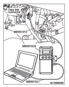
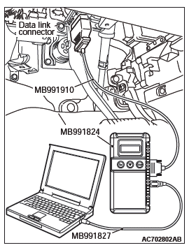
HOW TO CONNECT THE SCAN TOOL (M.U.T.-III)
Required Special Tools:
- MB991958: Scan Tool (M.U.T.-III Sub Assembly)
- MB991824: Vehicle Communication Interface (V.C.I.)
- MB991827: M.U.T.-III USB Cable
- MB991910: M.U.T.-III Main Harness A
CAUTION To prevent damage to scan tool MB991958, always turn the ignition switch to the "LOCK" (OFF) position before connecting or disconnecting scan tool MB991958.
1. Ensure that the ignition switch is at the "LOCK" (OFF) position.
2. Start up the personal computer.
3. Connect special tool MB991827 to special tool MB991824 and the personal computer.
4. Connect special tool MB991910 to special tool MB991824.
5. Connect special tool MB991910 to the data link connector.
6. Turn the power switch of special tool MB991824 to the "ON" position.
NOTE: When special tool MB991824 is energized, special tool MB991824 indicator light will be illuminated in a green color.
7. Start the scan tool system on the personal computer.
NOTE: Disconnecting scan tool MB991958 is the reverse of the connecting sequence, making sure that the ignition switch is at the "LOCK" (OFF) position.
HOW TO DIAGNOSE THE CAN BUS LINE
Required Special Tools:
- MB991958: Scan Tool (M.U.T.-III Sub Assembly)
- MB991824: Vehicle Communication Interface (V.C.I.)
- MB991827: M.U.T.-III USB Cable
- MB991910: M.U.T.-III Main Harness A
CAUTION To prevent damage to scan tool MB991958, always turn the ignition switch to the "LOCK" (OFF) position before connecting or disconnecting scan tool MB991958.
1. Connect scan tool MB991958 to the data link connector.
2. Turn the ignition switch to the "ON" position.
3. Select "CAN Bus Diagnosis" from the start-up screen.
4. When the vehicle information is displayed, confirm that it matches the vehicle whose CAN bus lines will be diagnosed.
- If they match, go to Step 8.
- If not, go to Step 5.
5. Select the "view vehicle information" button.
6. Enter the vehicle information and select the "OK" button.
7. When the vehicle information is displayed, confirm again that it matches the vehicle whose CAN bus lines will be diagnosed.
- If they match, go to Step 8.
- If not, go to Step 5.
8. Select the "OK" button.
9. When the optional equipment screen is displayed, choose the one which the vehicle is fitted with, and then select the "OK" button.
READ NEXT:
 Diagnosis
CAN BUS DIAGNOSTICS TABLE
CAUTION
A diagnostic trouble code may not also be set in
the CAN-B lines under the conditions below. If no
diagnostic trouble code has been set due to electrical
noise, confi
Diagnostic Item 1-5
DIAGNOSTIC ITEM 1: Diagnose when the scan tool cannot receive the data
sent by ETACS-ECU
CAUTION
When servicing a CAN bus line, ground yourself by touching a metal object such
as an unpainted
water
Diagnostic Item 6-13
DIAGNOSTIC ITEM 6: Diagnose when the scan tool cannot receive the data
sent by AWD-ECU
<Electronic controlled AWD>.
CAUTION
When servicing a CAN bus line, ground yourself by touching a metal ob
SEE MORE:
On-vehicle Service
ID CODES REGISTRATION PROCEDURE
REGISTRATION USING SCAN TOOL MB991958 (M.U.T.-III SUB ASSEMBLY)
Required Special Tools:
MB991958 Scan Tool (M.U.T.-III Sub Assembly)
MB991824: Vehicle Communication Interface (V.C.I.)
MB991827 M.U.T.-III USB Cable
MB991910 M.U.T.-III Main Harness A
By operating
Automatic Transaxle Overhaul
Transaxle Models
General Specifications
Service Specifications
Torque Specifications
Transaxle
Transfer
Size of torque wrench used
Adjusting Plate, Snap Ring,
Shim, Spacer, Needle Bearing,
Thrust Washer and
Bearing Race
Retaining plate (For adjustment of Low-reverse brake clearance)
Retaining
