Mitsubishi Outlander: Diagnostic Item 1-5
DIAGNOSTIC ITEM 1: Diagnose when the scan tool cannot receive the data sent by ETACS-ECU
CAUTION When servicing a CAN bus line, ground yourself by touching a metal object such as an unpainted water pipe. If you fail to do so, a component connected to the CAN bus line may be damaged.
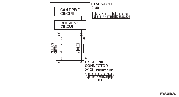
CAN Communication Circuit
FUNCTION
When the CAN bus diagnosis is carried out, the scan tool communicates with the ETACS-ECU. If a communication flag is not set for the ETACS-ECU, the ETACS-ECU will be diagnosed as a communication error.
TROUBLE JUDGMENT CONDITIONS
If a communication flag is not set for the ETACS-ECU, the Scan Tool determines that there is a failure.
TROUBLESHOOTING HINTS
- Malfunction of the connector (data link connector or ETACS-ECU connector improperly connected)
- Malfunction of the wiring harness (open circuit, short to ground, short to power supply between the data link connector and the ETACS-ECU connector, line-to-line short, or power supply to the ETACS-ECU)
- Malfunction of ETACS-ECU
DIAGNOSIS
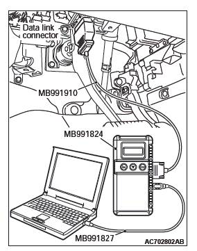
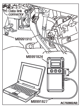
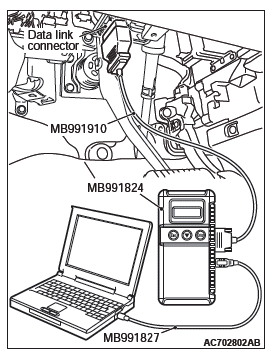
Required Special Tools:
- MB991223: Harness Set
- MB992006: Extra Fine Probe
- MB991958: Scan Tool (M.U.T.-III Sub Assembly)
- MB991824: Vehicle Communication Interface (V.C.I.)
- MB991827: M.U.T.-III USB Cable
- MB991910: M.U.T.-III Main Harness A
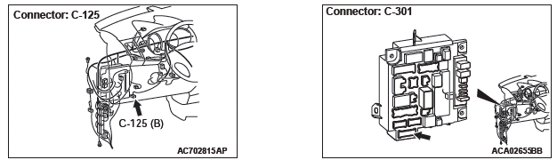
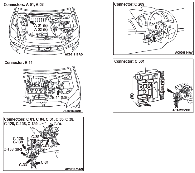
STEP 1. Check data link connector C-125 and ETACS-ECU connector C-301 for loose, corroded or damaged terminals, or terminals pushed back in the connector.
CAUTION The strand end of the twisted wire should be within 10 cm (4 inches) from the connector.
Q: Are data link connector C-125 and ETACS-ECU connector C-301 in good condition?
YES : Go to Step 2.
NO : Repair the damaged parts.
STEP 2. Check the wiring harness between data link connector C-125 and ETACS-ECU connector C-301 for open circuit.
CAUTION Strictly observe the specified wiring harness repair procedure.

(1) Disconnect the scan tool and ETACS-ECU connector C-301, and check the wiring harness.
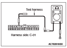
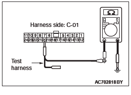
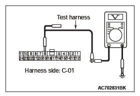
(2) Check the wiring harness between data link connector C-125 (terminal No.6) and ETACS-ECU connector C-301 (terminal No.5) <CAN_H>
OK: Continuity exists (2 ohms or less)
(3) Check the wiring harness between data link connector C-125 (terminal No.14) and ETACS-ECU connector C-301 (terminal No.4) <CAN_L>
OK: Continuity exists (2 ohms or less)
Q: Is the wiring harness between data link connector C-125 and ETACS-ECU connector C-301 in good condition?
YES : Go to Step 3.
NO : Repair the wiring harness between data link connector C-125 and ETACS-ECU connector C-301.
STEP 3. Check the wiring harness between data link connector C-125 and ETACS-ECU connector C-301 for a short to ground. Measure the resistance at data link connector C-125.
CAUTION Disconnect the negative battery terminal. CAUTION A digital multimeter should be used. CAUTION The test wiring harness should be used.
(1) Disconnect the scan tool and ETACS-ECU connector C-301, and measure the resistance at the wiring harness side of data link connector C-125.
(2) Measure the resistance between data link connector terminal 6 and body ground. <CAN_H>
OK: 1 kΩ or more
(3) Measure the resistance between data link connector terminal 14 and body ground. <CAN_L> OK: 1 kΩ or more
Q: Do all the resistances measure 1 kΩ or more?
YES : Go to Step 4.
NO : Repair the wiring harness between data link connector C-125 and ETACS-ECU connector C-301.
STEP 4. Check the wiring harness between data link connector C-125 and ETACS-ECU connector C-301 for a short to the power supply. Measure the voltage at data link connector C-125.
CAUTION Disconnect the negative battery terminal.
CAUTION A digital multimeter should be used.
CAUTION The test wiring harness should be used.
(1) Disconnect the scan tool and ETACS-ECU connector C-301, and measure the resistance at the wiring harness side of data link connector C-125.
(2) Turn the ignition switch to the "ON" position.
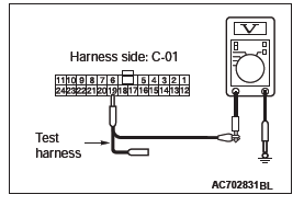
(3) Measure the voltage between data link connector terminal 6 and body ground. <CAN_H>
OK: 1 volts or less
(4) Measure the voltage between data link connector terminal 14 and body ground. <CAN_L>
OK: 1 volts or less
Q: Do all the voltage measure 5 volts or less?
YES : Go to Step 5.
NO : Repair the wiring harness between data link connector C-125 and ETACS-ECU connector C-301.
STEP 5. Check the wiring harness between data link connector C-125 and ETACS-ECU connector C-301 for line-to-line short. Measure the resistance at data link connector C-125.
CAUTION Disconnect the negative battery terminal. CAUTION A digital multimeter should be used. CAUTION The test wiring harness should be used.
(1) Disconnect the scan tool and ETACS-ECU connector C-301, and measure the resistance at the wiring harness side of data link connector C-125.
(2) Measure the resistance between data link connector terminal 6 and 14.
OK: No continuity
Q: Is the check result normal?
YES : Go to Step 6.
NO : Repair the wiring harness between data link connector C-125 and ETACS-ECU connector C-301
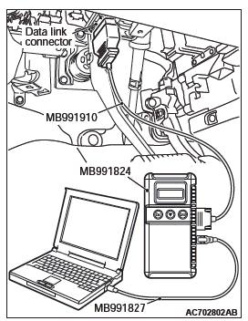
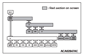
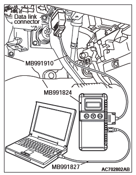
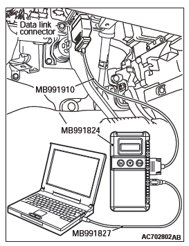
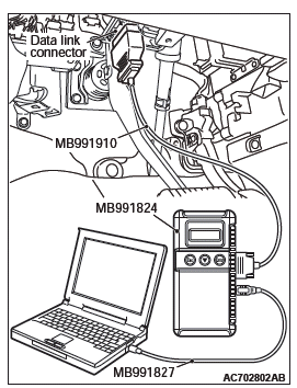
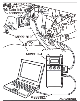
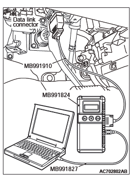
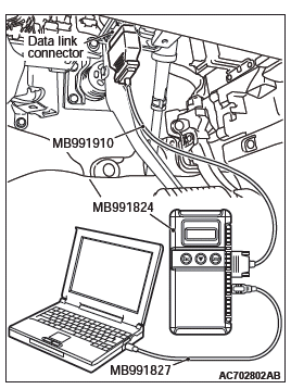
STEP 6. Using scan tool MB991958, diagnose the CAN bus line.
CAUTION To prevent damage to scan tool MB991958, always turn the ignition switch to the "LOCK" (OFF) position before connecting or disconnecting scan tool MB991958.
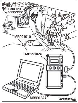
(1) Connect scan tool MB991958 to the data link connector.
(2) Turn the ignition switch to the "ON" position.
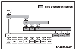
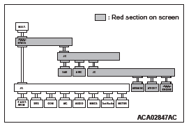
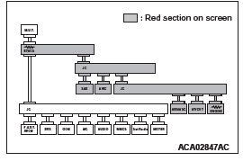
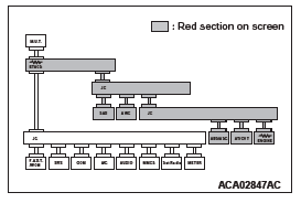
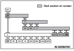
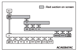
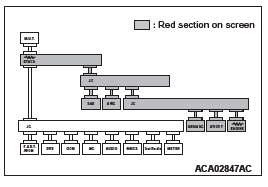
(3) Diagnose CAN bus lines, and check if the scan tool screen is as shown in the illustration.
Q: Does the scan tool screen correspond to the illustration?
YES : The trouble can be an intermittent malfunction.
NO : Replace the ETACS-ECU.
DIAGNOSTIC ITEM 2: Malfunction of the ETACS-ECU.
CAUTION When servicing a CAN bus line, ground yourself by touching a metal object such as an unpainted water pipe. If you fail to do, a component connected to the CAN bus line may be broken.
FUNCTION
When the CAN bus diagnosis is carried out, the scan tool sets communication "OK" flags in the patch between the ETACS-ECU and active other ECUs. If a commutation "OK" flag is not set for the ECUs other than the ETACS-ECU, this diagnosis result will be set.
TROUBLE JUDGEMENT CONDITIONS
If no communication flags are set for the ECUs (on the CAN-B or CAN-C lines) other than the ETACS-ECU, the ETACS-ECU determines that there is a failure.
TROUBLESHOOTING HINT
- Malfunction of the ETACS-ECU
DIAGNOSIS
Required Special Tools:
- MB991958: Scan Tool (M.U.T.-III Sub Assembly)
- MB991824: Vehicle Communication Interface (V.C.I.)
- MB991827: M.U.T.-III USB Cable
- MB991910: M.U.T.-III Main Harness A
Recheck for other system diagnostic trouble code.
CAUTION To prevent damage to scan tool MB991958, always turn the ignition switch to the "LOCK" (OFF) position before connecting or disconnecting scan tool MB991958.
Check whether ETACS-ECU-related DTC is set.
(1) Connect scan tool MB991958 to the data link connector.
(2) Turn the ignition switch to the "ON" position.
(3) Check if the DTC is set.
(4) Turn the ignition switch to the "LOCK" (OFF) position.
Q: Is the DTC set?
YES (The DTC other than the U code is set.) : Troubleshoot the ETACS-ECU.
YES (Only U-code DTC is set.) : Check the power supply circuit of the ETACS-ECU. NO (The DTC is not set.) : Check the power supply circuit of the ETACS-ECU.
DIAGNOSTIC ITEM 3: Abnormal short between the CAN-C bus lines.
CAUTION When servicing a CAN bus line, ground yourself by touching a metal object such as an unpainted water pipe. If you fail to do so, a component connected to the CAN bus line may be damaged.
CAN Communication Circuit
FUNCTION
If a line-to-line short is present in the CAN-C lines, this diagnosis result will be set.
TROUBLE JUDGMENT CONDITIONS
If only diagnostic trouble code U0001 is set, the ETACS-ECU determines that there is a failure.
TROUBLESHOOTING HINTS
- Malfunction of the connector (joint connectors or ECU connectors improperly connected)
- Malfunction of the wiring harness (line-to-line short in the CAN-C main or sub bus lines)
- Malfunction of the ECU (ECU on CAN-C lines failed)
DIAGNOSIS
Required Special Tools:
- MB991223: Harness Set
- MB992006: Extra Fine Probe
- MB991958: Scan Tool (M.U.T.-III Sub Assembly)
- MB991824: Vehicle Communication Interface (V.C.I.)
- MB991827: M.U.T.-III USB Cable
- MB991910: M.U.T.-III Main Harness A
- MB991970: ABS Check Harness
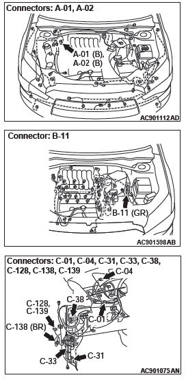
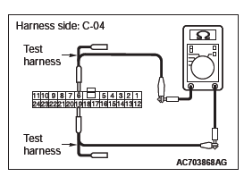
STEP 1. Check joint connector (CAN2) C-04 and joint connector (CAN3) for loose, corroded or damaged terminals, or terminals pushed back in the connector.
CAUTION The strand end of the twisted wire should be within 10 cm (4 inches) from the connector.
Q: Are joint connector (CAN2) C-04 and joint connector (CAN3) C-01 in good condition?
YES <vehicles with ASC> : Go to Step 2.
YES <vehicles without ASC (FWD)> : Go to Step 5.
YES <vehicles without ASC (Electric controlled AWD)> : Go to Step 3.
NO : Repair the damaged parts.
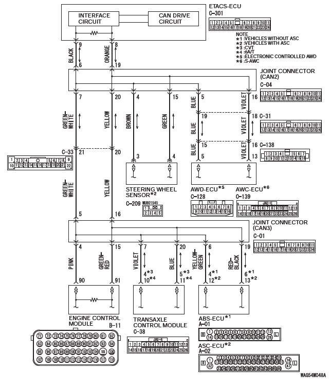
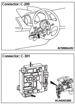
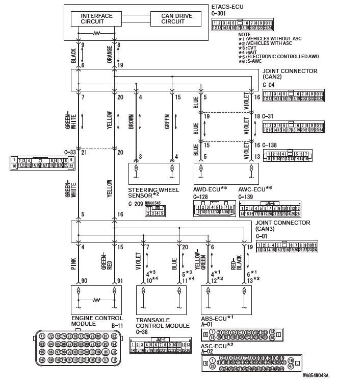
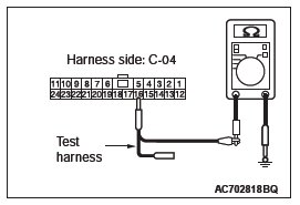
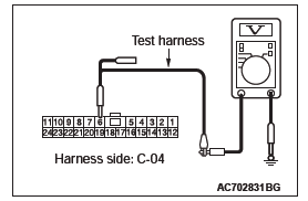
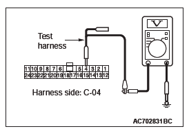
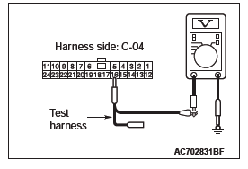
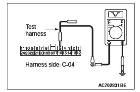
STEP 2. Check the wiring harness between joint connector (CAN2) C-04 and steering wheel sensor connector C-209 for line-to-line short. Measure the resistance at joint connector (CAN2) C-04.
CAUTION Disconnect the negative battery terminal.
CAUTION A digital multimeter should be used.
CAUTION The test wiring harness should be used.
(1) Disconnect joint connector (CAN2), and check that there is continuity at the harness side of joint connector (CAN2).
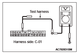
(2) Check that there is continuity between joint connector (CAN2) terminals 4 and 15.
OK: No continuity
Q: Is the check result normal?
YES <FWD> : Go to Step 5.
YES <Electric controlled AWD> : Go to Step 3.
YES <S-AWC> : Go to Step 4.
NO : Go to Step 9.
STEP 3. Check the wiring harness between joint connector (CAN2) C-04 and AWD-ECU connector C-128 for line-to-line short. Measure the resistance at joint connector (CAN2) C-04.
(1) Disconnect joint connector (CAN2), and check that there is continuity at the harness side of joint connector (CAN2).
(2) Check that there is continuity between joint connector (CAN2) terminals 5 and 16.
OK: No continuity
Q: Is the check result normal?
YES : Go to Step 5.
NO : Go to Step 10.
STEP 4. Check the wiring harness between joint connector (CAN2) C-04 and AWC-ECU connector C-139 for line-to-line short. Measure the resistance at joint connector (CAN2) C-04.
(1) Disconnect joint connector (CAN2), and check that there is continuity at the harness side of joint connector (CAN2).
(2) Check that there is continuity between joint connector (CAN2) terminals 5 and 16.
OK: No continuity
Q: Is the check result normal?
YES : Go to Step 5.
NO : Go to Step 11.
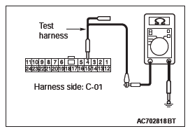
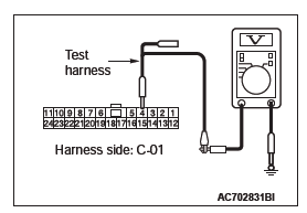
STEP 5. Check the wiring harness between joint connector (CAN3) C-01 and ECM connector B-11 for line-to-line short.
Measure the resistance at joint connector (CAN3) C-01.
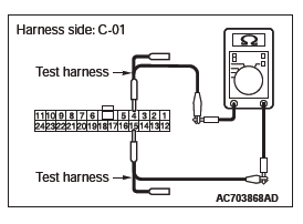
(1) Disconnect joint connector (CAN3), and check that there is continuity at the harness side of joint connector (CAN3).
(2) Check that there is continuity between joint connector (CAN3) terminals 4 and 15.
OK: No continuity
Q: Is the check result normal?
YES : Go to Step 6.
NO : Go to Step 12.
STEP 6. Check the wiring harness between joint connector (CAN3) C-01 and ABS-ECU connector A-01 <vehicles without ASC> or ASC-ECU connector A-02 <vehicles with ASC> for line-to-line short. Measure the resistance at joint connector (CAN3) C-01.
(1) Disconnect joint connector (CAN3), and check that there is continuity at the harness side of joint connector (CAN3).
(2) Check that there is continuity between joint connector (CAN3) terminals 6 and 19.
OK: No continuity
Q: Is the check result normal?
YES <CVT, A/T> : Go to Step 7.
YES <M/T> : Go to Step 8.
NO : Go to Step 13.
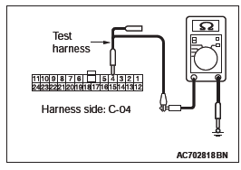
STEP 7. Check the wiring harness between joint connector (CAN3) C-01 and TCM connector C-38 for line-to-line short.
Measure the resistance at joint connector (CAN3) C-01.
(1) Disconnect joint connector (CAN3), and check that there is continuity at the harness side of joint connector (CAN3).
(2) Check that there is continuity between joint connector (CAN3) terminals 7 and 20.
OK: No continuity
Q: Is the check result normal?
YES : Go to Step 8.
NO : Go to Step 14.
STEP 8. Check the wiring harness between joint connector (CAN2) C-04 and ETACS-ECU connector C-301 for line-to-line short. Measure the resistance at joint connector (CAN2) C-04.
(1) Disconnect joint connector (CAN2), and check that there is continuity at the harness side of joint connector (CAN2).
(2) Check that there is continuity between joint connector (CAN2) terminals 6 and 19.
OK: No continuity
Q: Is the check result normal?
YES : Check intermediate connector C-33, and repair if necessary. If the intermediate connector is in good condition, repair the wiring harness between joint connector (CAN2) C-04 and joint connector (CAN3) C-01.
NO : Go to Step 15.
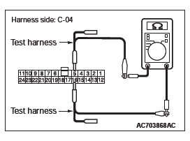
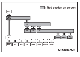
STEP 9. Using scan tool MB991958, diagnose the CAN bus line. (checking the steering wheel sensor for internal short)
CAUTION Strictly observe the specified wiring harness repair procedure.
CAUTION To prevent damage to scan tool MB991958, always turn the ignition switch to the "LOCK" (OFF) position before connecting or disconnecting scan tool MB991958.
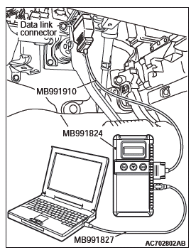
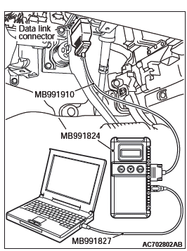
(1) Disconnect steering wheel sensor connector C-209.
(2) Connect scan tool MB991958 to the data link connector.
(3) Turn the ignition switch to the "ON" position.
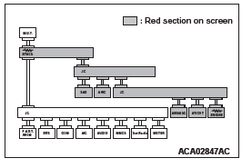
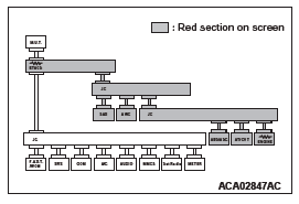
(4) Diagnose CAN bus lines, and check if the scan tool MB991958 screen is as shown in the figure.
OK: The display of the scan tool MB991958 is as shown in the figure.
Q: Does scan tool MB991958 screen correspond to the illustration?
YES : Repair the wiring harness between steering wheel sensor connector C-209 and joint connector (CAN2) C-04.
NO : Check steering wheel sensor connector C-209, and repair if necessary. If the steering wheel sensor connector is in good condition, replace the steering wheel sensor.
STEP 10. Using scan tool MB991958, diagnose the CAN bus line. (checking the AWD-ECU for internal short)
CAUTION Strictly observe the specified wiring harness repair procedure.
CAUTION To prevent damage to scan tool MB991958, always turn the ignition switch to the "LOCK" (OFF) position before connecting or disconnecting scan tool MB991958.
(1) Disconnect AWD-ECU connector C-128.
(2) Connect scan tool MB991958 to the data link connector.
(3) Turn the ignition switch to the "ON" position.
(4) Diagnose CAN bus lines, and check if the scan tool MB991958 screen is as shown in the figure.
OK: The display of the scan tool MB991958 is as shown in the figure.
Q: Does scan tool MB991958 screen correspond to the illustration?
YES : Check intermediate connectors C-31 and C-138, and repair if necessary. If the intermediate connector is in good condition, repair the wiring harness between AWD-ECU connector C-128 and joint connector (CAN2) C-04.
NO : Check AWD-ECU connector C-128, and repair if necessary. If the AWD-ECU connector is in good condition, replace the AWD-ECU.
STEP 11. Using scan tool MB991958, diagnose the CAN bus line. (checking the AWC-ECU for internal short).
CAUTION Strictly observe the specified wiring harness repair procedure.
CAUTION To prevent damage to scan tool MB991958, always turn the ignition switch to the "LOCK" (OFF) position before connecting or disconnecting scan tool MB991958.
(1) Disconnect AWC-ECU connector C-139.
(2) Connect scan tool MB991958 to the data link connector.
(3) Turn the ignition switch to the "ON" position.
(4) Diagnose CAN bus lines, and check if the scan tool MB991958 screen is as shown in the figure.
OK: The display of the scan tool MB991958 is as shown in the figure.
Q: Does scan tool MB991958 screen correspond to the illustration?
YES : Check intermediate connector C-31 and C-138, and repair if necessary. If the intermediate connector is in good condition, repair the wiring harness between AWC-ECU connector C-139 and joint connector (CAN2) C-04.
NO : Check AWC-ECU connector C-139, and repair if necessary. If the AWC-ECU connector is in good condition, replace the AWC-ECU.
STEP 12. Using scan tool MB991958, diagnose the CAN bus line. (checking the ECM for internal short).
CAUTION Strictly observe the specified wiring harness repair procedure.
CAUTION To prevent damage to scan tool MB991958, always turn the ignition switch to the "LOCK" (OFF) position before connecting or disconnecting scan tool MB991958.
(1) Disconnect ECM connector B-11.
(2) Connect scan tool MB991958 to the data link connector.
(3) Turn the ignition switch to the "ON" position.
(4) Diagnose CAN bus lines, and check if the scan tool MB991958 screen is as shown in the figure.
OK: The display of the scan tool MB991958 is as shown in the figure.
Q: Does scan tool MB991958 screen correspond to the illustration?
YES : Repair the wiring harness between ECM connector B-11 and joint connector (CAN3) C-01.
NO : Check ECM connector B-11, and repair if necessary.
If the ECM connector is in good condition, replace the ECM.
STEP 13. Using scan tool MB991958, diagnose the CAN bus line. (checking the ABS-ECU <vehicles without ASC> or ASC-ECU <vehicles with ASC> for internal short).
CAUTION Strictly observe the specified wiring harness repair procedure.
CAUTION To prevent damage to scan tool MB991958, always turn the ignition switch to the "LOCK" (OFF) position before connecting or disconnecting scan tool MB991958.
(1) Disconnect ABS-ECU connector A-01 <vehicles without ASC> or ASC-ECU connector A-02 <vehicles with ASC>.
(2) Connect scan tool MB991958 to the data link connector.
(3) Turn the ignition switch to the "ON" position.
(4) Diagnose CAN bus lines, and check if the scan tool MB991958 screen is as shown in the figure.
OK: The display of the scan tool MB991958 is as shown in the figure.
Q: Does scan tool MB991958 screen correspond to the illustration?
YES : Repair the wiring harness between ABS-ECU connector A-01 <vehicles without ASC> or ASC-ECU connector A-02 <vehicles with ASC> and joint connector (CAN3) C-01.
NO : Check ABS-ECU connector A-01 <vehicles without ASC> or ASC-ECU connector A-02 <vehicles with ASC>, and repair if necessary. If the ABS-ECU <vehicles without ASC> or ASC-ECU <vehicles with ASC> connector is in good condition, replace the ABS-ECU <vehicles without ASC> or ASC-ECU <vehicles with ASC>.
STEP 14. Using scan tool MB991958, diagnose the CAN bus line. (checking the TCM for internal short).
CAUTION Strictly observe the specified wiring harness repair procedure.
CAUTION To prevent damage to scan tool MB991958, always turn the ignition switch to the "LOCK" (OFF) position before connecting or disconnecting scan tool MB991958.
(1) Disconnect TCM connector C-38.
(2) Connect scan tool MB991958 to the data link connector.
(3) Turn the ignition switch to the "ON" position.
(4) Diagnose CAN bus lines, and check if the scan tool MB991958 screen is as shown in the figure.
OK: The display of the scan tool MB991958 is as shown in the figure.
Q: Does scan tool MB991958 screen correspond to the illustration?
YES : Repair the wiring harness between TCM connector C-38 and joint connector (CAN3) C-01.
NO : Check TCM connector C-38, and repair if necessary.
If the TCM connector is in good condition, replace the TCM.
STEP 15. Check the wiring harness between joint connector (CAN2) C-04 and ETACS-ECU connector C-301 for line-to-line short. Measure the resistance at joint connector (CAN2) C-04.
(1) Disconnect joint connector (CAN2) and ETACS-ECU connector, and check that there is continuity at the harness side of joint connector (CAN2).
(2) Check that there is continuity between joint connector (CAN2) terminals 6 and 19.
OK: No continuity.
Q: Is the check result normal?
YES : Go to Step 16.
NO : Repair the wiring harness between joint connector (CAN2) C-04 and ETACS-ECU connector C-301.
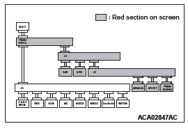
STEP 16. Using scan tool MB991958, diagnose the CAN bus line.
CAUTION To prevent damage to scan tool MB991958, always turn the ignition switch to the "LOCK" (OFF) position before connecting or disconnecting scan tool MB991958.
(1) Connect scan tool MB991958 to the data link connector.
(2) Turn the ignition switch to the "ON" position.

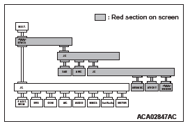
(3) Diagnose CAN bus lines, and check if the scan tool screen is as shown in the illustration.
Q: Does the scan tool screen correspond to the illustration?
YES : The trouble can be an intermittent malfunction.
NO : Replace the ETACS-ECU.
DIAGNOSTIC ITEM 4: Diagnose shorts in the ground to CAN-C bus line.
CAUTION When servicing a CAN bus line, ground yourself by touching a metal object such as an unpainted water pipe. If you fail to do so, a component connected to the CAN bus line may be damaged.
CAN Communication Circuit
FUNCTION
If a short to ground is present in the CAN-C lines, this diagnosis result will be set.
TROUBLE JUDGMENT CONDITIONS
If DTC U1120 is set, the ETACS-ECU determines that there is a failure.
TROUBLESHOOTING HINTS
- Malfunction of the connector (short to ground inside connector)
- Malfunction of the wiring harness (short to ground in the CAN-C main or sub bus lines)
- Malfunction of the ECU (ETACS-ECU, or ECUs on CAN-C lines failed)
DIAGNOSIS
Required Special Tools:
- MB991223: Harness Set
- MB992006: Extra Fine Probe
- MB991958: Scan Tool (M.U.T.-III Sub Assembly)
- MB991824: Vehicle Communication Interface (V.C.I.)
- MB991827: M.U.T.-III USB Cable
- MB991910: M.U.T.-III Main Harness A
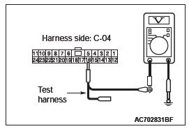
STEP 1. Check the wiring harness between joint connector (CAN2) C-04 and ETACS-ECU connector C-301 for a short to ground. Measure the resistance at joint connector (CAN2) C-04.
(1) Disconnect joint connector (CAN2), and measure the resistance at the wiring harness side of joint connector (CAN2).
(2) Measure the resistance between joint connector (CAN2) terminal 6 and body ground.
OK: 1 kΩ or more
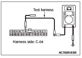
(3) Measure the resistance between joint connector (CAN2) terminal 19 and body ground.
OK: 1 kΩ or more
Q: Do all the resistances measure 1 kΩ or more?
YES <vehicles with ASC> : Go to Step 2.
YES <vehicles without ASC (FWD)> : Go to Step 5.
YES <vehicles without ASC (Electric controlled AWD)> : Go to Step 3.
NO : Go to Step 11.
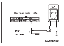
STEP 2. Check the wiring harness between joint connector (CAN2) C-04 and steering wheel sensor connector C-209 for a short to ground. Measure the resistance at joint connector (CAN2) C-04.
CAUTION Disconnect the negative battery terminal. CAUTION A digital multimeter should be used. CAUTION The test wiring harness should be used.
(1) Disconnect joint connector (CAN2), and measure the resistance at the wiring harness side of joint connector (CAN2).
(2) Measure the resistance between joint connector (CAN2) terminal 4 and body ground.
OK: 1 kΩ or more
(3) Measure the resistance between joint connector (CAN2) terminal 15 and body ground.
OK: 1 kΩ or more
Q: Do all the resistances measure 1 kΩ or more?
YES <FWD> : Go to Step 5.
YES <Electric controlled AWD> : Go to Step 3.
YES <S-AWC> : Go to Step 4.
NO : Go to Step 8.
STEP 3 Check the wiring harness between joint connector (CAN2) C-04 and AWD-ECU connector C-128 for a short to ground. Measure the resistance at joint connector (CAN2) C-04.
(1) Disconnect joint connector (CAN2), and measure the resistance at the wiring harness side of joint connector (CAN2).
(2) Measure the resistance between joint connector (CAN2) terminal 5 and body ground.
OK: 1 kΩ or more
(3) Measure the resistance between joint connector (CAN2) terminal 16 and body ground.
OK: 1 kΩ or more
Q: Do all the resistances measure 1 kΩ or more?
YES : Go to Step 5.
NO : Go to Step 9.
STEP 4 Check the wiring harness between joint connector (CAN2) C-04 and AWC-ECU connector C-139 for a short to ground. Measure the resistance at joint connector (CAN2) C-04.
(1) Disconnect joint connector (CAN2), and measure the resistance at the wiring harness side of joint connector (CAN2).
(2) Measure the resistance between joint connector (CAN2) terminal 5 and body ground.
OK: 1 kΩ or more
(3) Measure the resistance between joint connector (CAN2) terminal 16 and body ground.
OK: 1 kΩ or more
Q: Do all the resistances measure 1 kΩ or more?
YES : Go to Step 5.
NO : Go to Step 10.
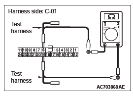
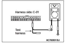
STEP 5. Check the wiring harness between joint connector (CAN3) C-01 and ECM connector B-11 for a short to ground. Measure the resistance at joint connector (CAN3) C-01.
(1) Disconnect joint connector (CAN3), and measure the resistance at the wiring harness side of joint connector (CAN3).
(2) Measure the resistance between joint connector (CAN3) terminal 4 and body ground.
OK: 1 kΩ or more
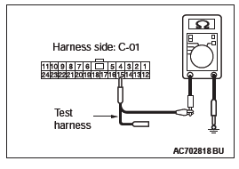
(3) Measure the resistance between joint connector (CAN3) terminal 15 and body ground.
OK: 1 kΩ or more
Q: Do all the resistances measure 1 kΩ or more?
YES : Go to Step 6.
NO : Go to Step 12.
STEP 6. Check the wiring harness between joint connector (CAN3) C-01 and ABS-ECU connector A-01 <vehicles without ASC> or ASC-ECU connector A-02 <vehicles with ASC> for a short to ground. Measure the resistance at joint connector (CAN3) C-01.
(1) Disconnect joint connector (CAN3), and measure the resistance at the wiring harness side of joint connector (CAN3).
(2) Measure the resistance between joint connector (CAN3) terminal 6 and body ground.
OK: 1 kΩ or more

(3) Measure the resistance between joint connector (CAN3) terminal 19 and body ground.
OK: 1 kΩ or more
Q: Do all the resistances measure 1 kΩ or more?
YES <CVT, A/T> : Go to Step 7.
YES <M/T> : Check intermediate connector C-33, and repair if necessary. If the intermediate connector is in good condition, repair the wiring harness between joint connector (CAN2) C-04 and joint connector (CAN3) C-01.
NO : Go to Step 13.
STEP 7. Check the wiring harness between joint connector (CAN3) C-01 and TCM connector C-38 for a short to ground. Measure the resistance at joint connector (CAN3) C-01.
(1) Disconnect joint connector (CAN3), and measure the resistance at the wiring harness side of joint connector (CAN3).
(2) Measure the resistance between joint connector (CAN3) terminal 7 and body ground.
OK: 1 kΩ or more
(3) Measure the resistance between joint connector (CAN3) terminal 20 and body ground.
OK: 1 kΩ or more
Q: Do all the resistances measure 1 kΩ or more?
YES : Check intermediate connector C-27, and repair if necessary. If the intermediate connector is in good condition, repair the wiring harness between joint connector (CAN2) C-04 and joint connector (CAN3) C-01.
NO : Go to Step 14.
STEP 8. Using scan tool MB991958, diagnose the CAN bus line. (checking the steering wheel sensor for internal short to ground)
CAUTION Strictly observe the specified wiring harness repair procedure.
CAUTION To prevent damage to scan tool MB991958, always turn the ignition switch to the "LOCK" (OFF) position before connecting or disconnecting scan tool MB991958.
(1) Disconnect steering wheel sensor connector C-209.
(2) Connect scan tool MB991958 to the data link connector.
(3) Turn the ignition switch to the "ON" position.
(4) Diagnose CAN bus lines, and check if the scan tool MB991958 screen is as shown in the figure.
OK: The display of the scan tool MB991958 is as shown in the figure.
Q: Does scan tool MB991958 screen correspond to the illustration?
YES : Repair the wiring harness between steering wheel sensor connector C-209 and joint connector (CAN2) C-04.
NO : Check steering wheel sensor connector C-209, and repair if necessary. If the steering wheel sensor connector is in good condition, replace the steering wheel sensor.
STEP 9. Using scan tool MB991958, diagnose the CAN bus line. (checking the AWD-ECU for internal short to ground).
CAUTION Strictly observe the specified wiring harness repair procedure.
CAUTION To prevent damage to scan tool MB991958, always turn the ignition switch to the "LOCK" (OFF) position before connecting or disconnecting scan tool MB991958.
(1) Disconnect AWD-ECU connector C-128.
(2) Connect scan tool MB991958 to the data link connector.
(3) Turn the ignition switch to the "ON" position.
(4) Diagnose CAN bus lines, and check if the scan tool MB991958 screen is as shown in the figure.
OK: The display of the scan tool MB991958 is as shown in the figure.
Q: Does scan tool MB991958 screen correspond to the illustration?
YES : Check intermediate connector C-31 and C-138, and repair if necessary. If the intermediate connector is in good condition, repair the wiring harness between AWD-ECU connector C-128 and joint connector (CAN2) C-04.
NO : Check AWD-ECU connector C-128, and repair if necessary. If the AWD-ECU connector is in good condition, replace the AWD-ECU.
STEP 10. Using scan tool MB991958, diagnose the CAN bus line. (checking the AWC-ECU for internal short to ground).
CAUTION Strictly observe the specified wiring harness repair procedure.
CAUTION To prevent damage to scan tool MB991958, always turn the ignition switch to the "LOCK" (OFF) position before connecting or disconnecting scan tool MB991958.
(1) Disconnect AWC-ECU connector C-139.
(2) Connect scan tool MB991958 to the data link connector.
(3) Turn the ignition switch to the "ON" position.
(4) Diagnose CAN bus lines, and check if the scan tool MB991958 screen is as shown in the figure.
OK: The display of the scan tool MB991958 is as shown in the figure.
Q: Does scan tool MB991958 screen correspond to the illustration?
YES : Check intermediate connector C-31 and C-138, and repair if necessary. If the intermediate connector is in good condition, repair the wiring harness between AWC-ECU connector C-139 and joint connector (CAN2) C-04.
NO : Check AWC-ECU connector C-139, and repair if necessary. If the AWC-ECU connector is in good condition, replace the AWC-ECU.
STEP 11. Check the wiring harness between joint connector (CAN2) C-04 and ETACS-ECU connector C-301 for a short to ground.
CAUTION Disconnect the negative battery terminal. CAUTION A digital multimeter should be used. CAUTION The test wiring harness should be used. CAUTION Strictly observe the specified wiring harness repair procedure.
(1) Disconnect ETACS-ECU connector and joint connector (CAN2), and measure at the wiring harness side.
(2) Measure the resistance between joint connector (CAN2) terminal 6 and body ground.
OK: 1 kΩ or more
(3) Measure the resistance between joint connector (CAN2) terminal 19 and body ground.
OK: 1 kΩ or more
Q: Do all the resistances measure 1 kΩ or more?
YES : Check ETACS-ECU connector C-301, and repair if necessary. If the ETACS-ECU connector is in good condition, replace the ETACS-ECU.
NO : Repair the wiring harness between ETACS-ECU connector C-301 and joint connector (CAN2) C-04.
STEP 12. Using scan tool MB991958, diagnose the CAN bus line. (checking the ECM for internal short to ground).
CAUTION Strictly observe the specified wiring harness repair procedure.
CAUTION To prevent damage to scan tool MB991958, always turn the ignition switch to the "LOCK" (OFF) position before connecting or disconnecting scan tool MB991958.
(1) Disconnect ECM connector B-11.
(2) Connect scan tool MB991958 to the data link connector.
(3) Turn the ignition switch to the "ON" position.
(4) Diagnose CAN bus lines, and check if the scan tool MB991958 screen is as shown in the figure.
OK: The display of the scan tool MB991958 is as shown in the figure.
Q: Does scan tool MB991958 screen correspond to the illustration?
YES : Repair the wiring harness between ECM connector B-11 and joint connector (CAN3) C-01.
NO : Check ECM connector B-11, and repair if necessary.
If the ECM connector is in good condition, replace the ECM.
STEP 13. Using scan tool MB991958, diagnose the CAN bus line. (checking the ABS-ECU <vehicles without ASC> or ASC-ECU <vehicles with ASC> for internal short to ground).
CAUTION Strictly observe the specified wiring harness repair procedure.
CAUTION To prevent damage to scan tool MB991958, always turn the ignition switch to the "LOCK" (OFF) position before connecting or disconnecting scan tool MB991958.
(1) Disconnect ABS-ECU connector A-01 <vehicles without ASC> or ASC-ECU connector A-02 <vehicles with ASC>.
(2) Connect scan tool MB991958 to the data link connector.
(3) Turn the ignition switch to the "ON" position.
(4) Diagnose CAN bus lines, and check if the scan tool MB991958 screen is as shown in the figure.
OK: The display of the scan tool MB991958 is as shown in the figure.
Q: Does scan tool MB991958 screen correspond to the illustration?
YES : Repair the wiring harness between ABS-ECU connector A-01 <vehicles without ASC> or ASC-ECU connector A-02 <vehicles with ASC> and joint connector (CAN3) C-01.
NO : Check ABS-ECU connector A-01 <vehicles without ASC> or ASC-ECU connector A-02 <vehicles with ASC>, and repair if necessary. If the ABS-ECU connector <vehicles without ASC> or ASC-ECU connector <vehicles with ASC> is in good condition, replace the ABS-ECU <vehicles without ASC> or ASC-ECU <vehicles with ASC>.
STEP 14. Using scan tool MB991958, diagnose the CAN bus line. (checking the TCM for internal short to ground).
CAUTION Strictly observe the specified wiring harness repair procedure.
CAUTION To prevent damage to scan tool MB991958, always turn the ignition switch to the "LOCK" (OFF) position before connecting or disconnecting scan tool MB991958.
(1) Disconnect TCM connector C-38.
(2) Connect scan tool MB991958 to the data link connector.
(3) Turn the ignition switch to the "ON" position.
(4) Diagnose CAN bus lines, and check if the scan tool MB991958 screen is as shown in the figure.
OK: The display of the scan tool MB991958 is as shown in the figure.
Q: Does scan tool MB991958 screen correspond to the illustration?
YES : Repair the wiring harness between TCM connector C-38 and joint connector (CAN3) C-01.
NO : Check TCM connector C-38, and repair if necessary.
If the TCM connector is in good condition, replace the TCM.
DIAGNOSTIC ITEM 5: Diagnose shorts in the power supply to CAN-C bus line.
CAUTION When servicing a CAN bus line, ground yourself by touching a metal object such as an unpainted water pipe. If you fail to do so, a component connected to the CAN bus line may be damaged.
CAN Communication Circuit
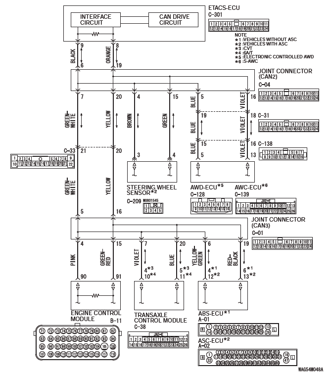
FUNCTION
If a short to power supply is present in the CAN-C lines, this diagnosis result will be set.
TROUBLE JUDGMENT CONDITIONS
The wiring harness wire or connectors may have loose, corroded, or damage terminals, or terminals pushed back in the connector, or an ECU may be defective.
TROUBLESHOOTING HINTS
- Malfunction of the connector (short to power supply in connector)
- Malfunction of the wiring harness (short to power supply in the CAN-C main or sub bus lines)
- Malfunction of the ECU (ETACS-ECU, or ECUs on CAN-C lines failed)
DIAGNOSIS
Required Special Tools:
- MB991223: Harness Set
- MB992006: Extra Fine Probe
- MB991958: Scan Tool (M.U.T.-III Sub Assembly)
- MB991824: Vehicle Communication Interface (V.C.I.)
- MB991827: M.U.T.-III USB Cable
- MB991910: M.U.T.-III Main Harness A
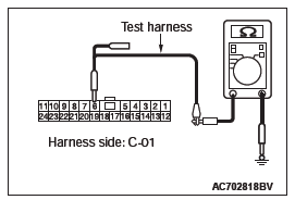
STEP 1. Check the wiring harness between joint connector (CAN2) C-04 and ETACS-ECU connector C-301 for a short to power supply. Measure the voltage at joint connector (CAN2) C-04.
(1) Disconnect joint connector (CAN2), and measure the voltage at the wiring harness side of joint connector (CAN2).
(2) Turn the ignition switch to the ON position.
(3) Measure the voltage between joint connector (CAN2) terminal 6 and body ground.
OK: 4.7 volts or less
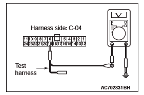
(4) Measure the voltage between joint connector (CAN2) terminal 19 and body ground.
OK: 4.7 volts or less
Q: Do all the voltages measure 4.7 volts or less?
YES <vehicles with ASC> : Go to Step 2.
YES <vehicles without ASC (FWD)> : Go to Step 5.
YES <vehicles without ASC (Electric controlled AWD)> : Go to Step 3.
NO : Go to Step 11.
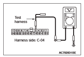
STEP 2. Check the wiring harness between joint connector (CAN2) C-04 and steering wheel sensor connector C-209 for a short to power supply. Measure the voltage at joint connector (CAN2) C-04.
CAUTION A digital multimeter should be used.
CAUTION The test wiring harness should be used.
(1) Disconnect joint connector (CAN2), and measure the voltage at the wiring harness side of joint connector (CAN2).
(2) Turn the ignition switch to the ON position.
(3) Measure the voltage between joint connector (CAN2) terminal 4 and body ground.
OK: 4.7 volts or less
(4) Measure the voltage between joint connector (CAN2) terminal 15 and body ground.
OK: 4.7 volts or less
Q: Do all the voltages measure 4.7 volts or less?
YES <FWD> : Go to Step 5.
YES <Electric controlled AWD> : Go to Step 3.
YES <S-AWC> : Go to Step 4.
NO : Go to Step 8.
STEP 3. Check the wiring harness between joint connector (CAN2) C-04 and AWD-ECU connector C-128 for a short to power supply. Measure the voltage at joint connector (CAN2) C-04.
(1) Disconnect joint connector (CAN2), and measure the voltage at the wiring harness side of joint connector (CAN2).
(2) Turn the ignition switch to the ON position.
(3) Measure the voltage between joint connector (CAN2) terminal 5 and body ground.
OK: 4.7 volts or less
(4) Measure the voltage between joint connector (CAN2) terminal 16 and body ground.
OK: 4.7 volts or less
Q: Do all the voltages measure 4.7 volts or less?
YES : Go to Step 5.
NO : Go to Step 9.
STEP 4. Check the wiring harness between joint connector (CAN2) C-04 and AWC-ECU connector C-139 for a short to power supply. Measure the voltage at joint connector (CAN2) C-04.
(1) Disconnect joint connector (CAN2), and measure the voltage at the wiring harness side of joint connector (CAN2).
(2) Turn the ignition switch to the ON position.
(3) Measure the voltage between joint connector (CAN2) terminal 5 and body ground.
OK: 4.7 volts or less
(4) Measure the voltage between joint connector (CAN2) terminal 16 and body ground.
OK: 4.7 volts or less
Q: Do all the voltages measure 4.7 volts or less?
YES : Go to Step 5.
NO : Go to Step 10.
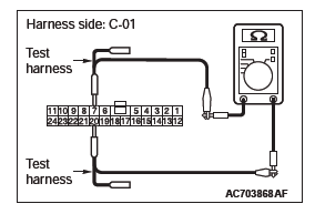
STEP 5. Check the wiring harness between joint connector (CAN3) C-01 and ECM connector B-11 for a short to power supply. Measure the voltage at joint connector (CAN3) C-01.
(1) Disconnect joint connector (CAN3), and measure the voltage at the wiring harness side of joint connector (CAN3).
(2) Turn the ignition switch to the ON position.
(3) Measure the voltage between joint connector (CAN3) terminal 4 and body ground.
OK: 4.7 volts or less
(4) Measure the voltage between joint connector (CAN3) terminal 15 and body ground.
OK: 4.7 volts or less
Q: Do all the voltages measure 4.7 volts or less?
YES : Go to Step 6.
NO : Go to Step 12.
STEP 6. Check the wiring harness between joint connector (CAN3) C-01 and ABS-ECU connector A-01 <vehicles without ASC> or ASC-ECU connector A-02 <vehicles with ASC> for a short to power supply. Measure the voltage at joint connector (CAN3) C-01.
(1) Disconnect joint connector (CAN3), and measure the voltage at the wiring harness side of joint connector (CAN3).
(2) Turn the ignition switch to the ON position.
(3) Measure the voltage between joint connector (CAN3) terminal 6 and body ground.
OK: 4.7 volts or less
(4) Measure the voltage between joint connector (CAN3) terminal 19 and body ground.
OK: 4.7 volts or less
Q: Do all the voltages measure 4.7 volts or less?
YES <CVT, A/T> : Go to Step 7.
YES <M/T> : Check intermediate connector C-33, and repair if necessary. If the intermediate connector is in good condition, repair the wiring harness between joint connector (CAN2) C-04 and joint connector (CAN3) C-01.
NO : Go to Step 13.
STEP 7. Check the wiring harness between joint connector (CAN3) C-01 and TCM connector C-38 for a short to power supply. Measure the voltage at joint connector (CAN3) C-01.
(1) Disconnect joint connector (CAN3), and measure the voltage at the wiring harness side of joint connector (CAN3).
(2) Turn the ignition switch to the ON position.
(3) Measure the voltage between joint connector (CAN3) terminal 7 and body ground.
OK: 4.7 volts or less
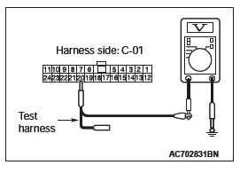
(4) Measure the voltage between joint connector (CAN3) terminal 20 and body ground.
OK: 4.7 volts or less
Q: Do all the voltages measure 4.7 volts or less?
YES : Check intermediate connector C-27, and repair if necessary. If the intermediate connector is in good condition, repair the wiring harness between joint connector (CAN2) C-04 and joint connector (CAN3) C-01.
NO : Go to Step 14.
STEP 8. Using scan tool MB991958, diagnose the CAN bus line. (checking the steering wheel sensor for internal short to ground).
CAUTION Strictly observe the specified wiring harness repair procedure.
CAUTION To prevent damage to scan tool MB991958, always turn the ignition switch to the "LOCK" (OFF) position before connecting or disconnecting scan tool MB991958.
(1) Disconnect steering wheel sensor connector C-209.
(2) Connect scan tool MB991958 to the data link connector.
(3) Turn the ignition switch to the "ON" position.
(4) Diagnose CAN bus lines, and check if the scan tool MB991958 screen is as shown in the figure.
OK: The display of the scan tool MB991958 is as shown in the figure.
Q: Does scan tool MB991958 screen correspond to the illustration?
YES : Repair the wiring harness between steering wheel sensor connector C-209 and joint connector (CAN2) C-04.
NO : Check steering wheel sensor connector C-209, and repair if necessary. If the steering wheel sensor connector is in good condition, replace the steering wheel sensor.
STEP 9. Using scan tool MB991958, diagnose the CAN bus line. (checking the AWD-ECU for internal short to ground).
CAUTION Strictly observe the specified wiring harness repair procedure.
CAUTION To prevent damage to scan tool MB991958, always turn the ignition switch to the "LOCK" (OFF) position before connecting or disconnecting scan tool MB991958.
(1) Disconnect AWD-ECU connector C-128.
(2) Connect scan tool MB991958 to the data link connector.
(3) Turn the ignition switch to the "ON" position.
(4) Diagnose CAN bus lines, and check if the scan tool MB991958 screen is as shown in the figure.
OK: The display of the scan tool MB991958 is as shown in the figure.
Q: Does scan tool MB991958 screen correspond to the illustration?
YES : Check intermediate connector C-31 and C-138, and repair if necessary. If the intermediate connector is in good condition, repair the wiring harness between AWD-ECU connector C-128 and joint connector (CAN2) C-04.
NO : Check AWD-ECU connector C-128, and repair if necessary. If the AWD-ECU connector is in good condition, replace the AWD-ECU.
STEP 10. Using scan tool MB991958, diagnose the CAN bus line. (checking the AWC-ECU for internal short to ground).
CAUTION Strictly observe the specified wiring harness repair procedure.
CAUTION To prevent damage to scan tool MB991958, always turn the ignition switch to the "LOCK" (OFF) position before connecting or disconnecting scan tool MB991958.
(1) Disconnect AWC-ECU connector C-139.
(2) Connect scan tool MB991958 to the data link connector.
(3) Turn the ignition switch to the "ON" position.
(4) Diagnose CAN bus lines, and check if the scan tool MB991958 screen is as shown in the figure.
OK: The display of the scan tool MB991958 is as shown in the figure.
Q: Does scan tool MB991958 screen correspond to the illustration?
YES : Check intermediate connector C-31 and C-138, and repair if necessary. If the intermediate connector is in good condition, repair the
READ NEXT:
 Diagnostic Item 6-13
DIAGNOSTIC ITEM 6: Diagnose when the scan tool cannot receive the data
sent by AWD-ECU
<Electronic controlled AWD>.
CAUTION
When servicing a CAN bus line, ground yourself by touching a metal ob
Diagnostic Item 14-23
DIAGNOSTIC ITEM 14: Diagnose the lines between joint connector (CAN2)
and joint connector
(CAN3).
CAUTION
When servicing a CAN bus line, ground yourself by touching a metal object such
as an unpain
Diagnostic Item 24-25
DIAGNOSTIC ITEM 24: Short to power supply or ground in both CAN_H and
CAN_L lines of the
CAN-B bus lines.
CAUTION
When servicing a CAN bus line, ground yourself
by touching a metal object such as an
SEE MORE:
Front Axle Hub Assembly
REMOVAL AND INSTALLATION
CAUTION
The magnetic encoder collects metallic particles easily, because it
is magnetized. Make sure that
the magnetic encoder should not collect metallic particles. Check that there
is not any trouble
prior to reassembling it.
When removing and installing the fron
DTC P0703, P0705, P0711, P0712, P0713, P0715, P0720, P0725, P0740,
P0741, P0745
DTC P0703: Malfunction of Stoplight Switch
Stoplight switch system circuit
DIAGNOSTIC FUNCTION
TCM detects malfunction using the stoplight switch
signal sent from the ETACS-ECU.
DESCRIPTIONS OF MONITOR METHODS
Drive the vehicle at 30 km/h (19 mph) or more for
10 seconds, and then turn the igni
