Mitsubishi Outlander: Diagnostic Item 24-25
DIAGNOSTIC ITEM 24: Short to power supply or ground in both CAN_H and CAN_L lines of the CAN-B bus lines.
CAUTION When servicing a CAN bus line, ground yourself by touching a metal object such as an unpainted water pipe. If you fail to do so, a component connected to the CAN bus line may be damaged.
CAN Communication Circuit

FUNCTION
If a short to power supply or ground is present in both CAN_H and CAN_L lines, this diagnosis result will be set.
TROUBLE JUDGMENT CONDITIONS
If a communication flag is set for the ETACS-ECU, no communication is present through the CAN-B line, and diagnostic trouble code U0019 is set, the ETACS-ECU determines that there is a failure.
TROUBLESHOOTING HINTS
- Malfunction of the connector (ETACS-ECU connector improperly connected)
- Malfunction of the wiring harness (CAN_H and CAN_L lines are short to power supply or ground on the CAN-B line.)
- Malfunction of ECUs
DIAGNOSIS
Required Special Tools:
- MB991223: Harness Set
- MB992006: Extra Fine Probe
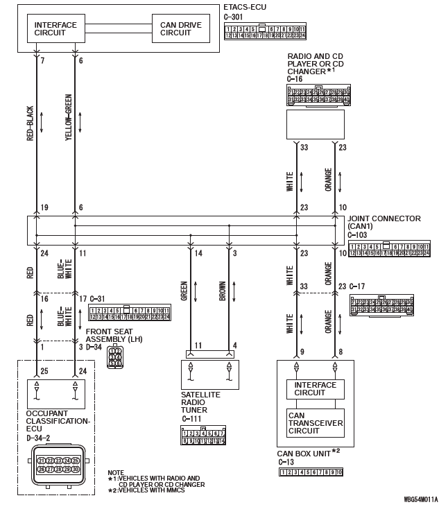
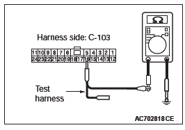
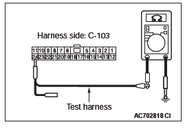
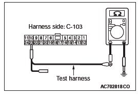
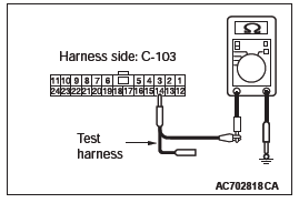
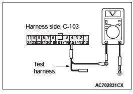
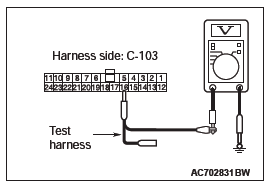
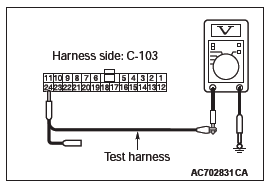
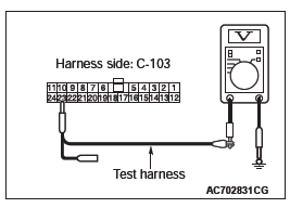
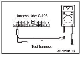
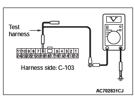
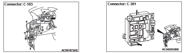
STEP 1. Check the wiring harness between ETACS-ECU connector C-301 and body ground for a short to power supply. Measure the voltage at ETACS-ECU connector C-301.
CAUTION A digital multimeter should be used. CAUTION The test wiring harness should be used.
(1) Disconnect ETACS-ECU connector C-301, and measure the voltage at the wiring harness side of ETACS-ECU connector.
(2) Turn the ignition switch to the ON position.
(3) Measure the voltage between ETACS-ECU connector terminal 6 and body ground.
OK: 4.7 volts or less
(4) Measure the voltage between ETACS-ECU connector terminal 7 and body ground.
OK: 4.7 volts or less
Q: Do all the voltages measure 4.7 volts or less?
YES : Go to Step 2.
NO : Go to Step 12.
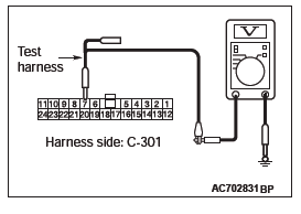
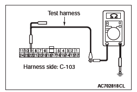
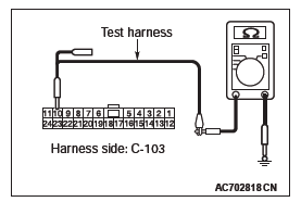
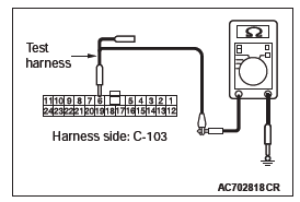
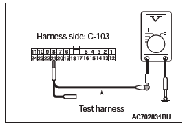
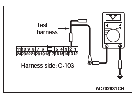
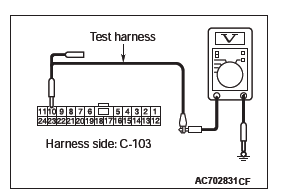
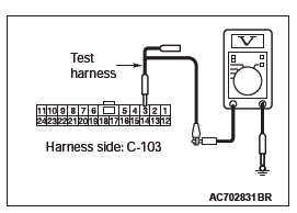
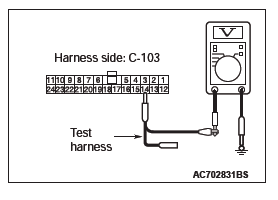
STEP 2. Check the wiring harness between joint connector (CAN1) C-103 and combination meter connector C-03 for a short to ground. Measure the resistance at joint connector (CAN1) C-103.
(1) Disconnect joint connector (CAN1), and measure the resistance at the wiring harness side of joint connector (CAN1).
(2) Measure the resistance between joint connector (CAN1) terminal 4 and body ground.
OK: 1 kΩ or more
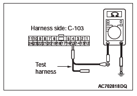
(3) Measure the resistance between joint connector (CAN1) terminal 15 and body ground.
OK: 1 kΩ or more
Q: Do all the resistances measure 1 kΩ or more?
YES (vehicles with KOS) : Go to Step 3.
YES (vehicles with WCM) : Go to Step 4.
NO (vehicles with KOS or WCM) : Go to Step 22.
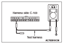
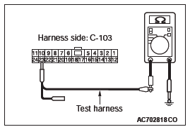
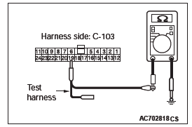
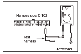
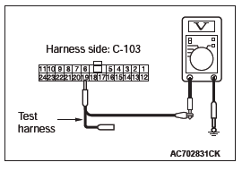
STEP 3. Check the wiring harness between joint connector (CAN1) C-103 and KOS-ECU connector C-102 for a short to ground. Measure the resistance at joint connector (CAN1) C-103.
(1) Disconnect joint connector (CAN1), and measure the resistance at the wiring harness side of joint connector (CAN1).
(2) Measure the resistance between joint connector (CAN1) terminal 8 and body ground.
OK: 1 kΩ or more
(3) Measure the resistance between joint connector (CAN1) terminal 21 and body ground.
OK: 1 kΩ or more
Q: Do all the resistances measure 1 kΩ or more?
YES : Go to Step 5.
NO : Go to Step 23.
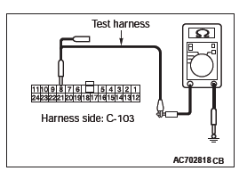
STEP 4. Check the wiring harness between joint connector (CAN1) C-103 and WCM connector C-29 for a short to ground. Measure the resistance at joint connector (CAN1) C-103.
(1) Disconnect joint connector (CAN1), and measure the resistance at the wiring harness side of joint connector (CAN1).
(2) Measure the resistance between joint connector (CAN1) terminal 5 and body ground.
OK: 1 kΩ or more
(3) Measure the resistance between joint connector (CAN1) terminal 16 and body ground.
OK: 1 kΩ or more
Q: Do all the resistances measure 1 kΩ or more?
YES : Go to Step 5.
NO : Go to Step 24.
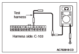
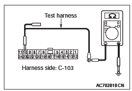
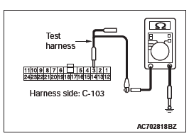
STEP 5. Check the wiring harness between joint connector (CAN1) C-103 and SRS-ECU connector C-28 for a short to ground. Measure the resistance at joint connector (CAN1) C-103.
(1) Disconnect joint connector (CAN1), and measure the resistance at the wiring harness side of joint connector (CAN1).
(2) Measure the resistance between joint connector (CAN1) terminal 2 and body ground.
OK: 1 kΩ or more
(3) Measure the resistance between joint connector (CAN1) terminal 13 and body ground.
OK: 1 kΩ or more
Q: Do all the resistances measure 1 kΩ or more?
YES : Go to Step 6.
NO : Go to Step 25.
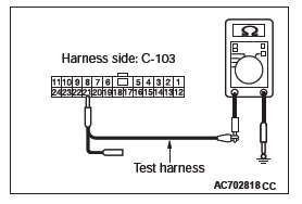
STEP 6. Check the wiring harness between joint connector (CAN1) C-103 and occupant classification-ECU connector D-34-2 for a short to ground. Measure the resistance at joint connector (CAN1) C-103.
(1) Disconnect joint connector (CAN1), and measure the resistance at the wiring harness side of joint connector (CAN1).
(2) Measure the resistance between joint connector (CAN1) terminal 11 and body ground.
OK: 1 kΩ or more
(3) Measure the resistance between joint connector (CAN1) terminal 24 and body ground.
OK: 1 kΩ or more
Q: Do all the resistances measure 1 kΩ or more?
YES : Go to Step 7.
NO : Go to Step 26.
STEP 7. Check the wiring harness between joint connector (CAN1) C-103 and A/C-ECU connector C-109 for a short to ground. Measure the resistance at joint connector (CAN1) C-103.
(1) Disconnect joint connector (CAN1), and measure the resistance at the wiring harness side of joint connector (CAN1).
(2) Measure the resistance between joint connector (CAN1) terminal 9 and body ground.
OK: 1 kΩ or more
(3) Measure the resistance between joint connector (CAN1) terminal 22 and body ground.
OK: 1 kΩ or more
Q: Do all the resistances measure 1 kΩ or more?
YES (vehicles without MMCS) : Go to Step 8.
YES (vehicles with MMCS) : Go to Step 9.
NO : Go to Step 27.
STEP 8. Check the wiring harness between joint connector (CAN1) C-103 and radio and CD player or radio and CD changer connector C-16 for a short to ground. Measure the resistance at joint connector (CAN1) C-103.
(1) Disconnect joint connector (CAN1), and measure the resistance at the wiring harness side of joint connector (CAN1).
(2) Measure the resistance between joint connector (CAN1) terminal 10 and body ground.
OK: 1 kΩ or more
(3) Measure the resistance between joint connector (CAN1) terminal 23 and body ground.
OK: 1 kΩ or more
Q: Do all the resistances measure 1 kΩ or more?
YES (vehicles without satellite radio) : Go to Step 11.
YES (vehicles with satellite radio) : Go to Step 10.
NO : Go to Step 28.
STEP 9. Check the wiring harness between joint connector (CAN1) C-103 and CAN box unit connector C-13 for a short to ground. Measure the resistance at joint connector (CAN1) C-103.
(1) Disconnect joint connector (CAN1), and measure the resistance at the wiring harness side of joint connector (CAN1).
(2) Measure the resistance between joint connector (CAN1) terminal 10 and body ground.
OK: 1 kΩ or more
(3) Measure the resistance between joint connector (CAN1) terminal 23 and body ground.
OK: 1 kΩ or more
Q: Do all the resistances measure 1 kΩ or more?
YES (vehicles without satellite radio) : Go to Step 11.
YES (vehicles with satellite radio) : Go to Step 10.
NO : Go to Step 29.
STEP 10. Check the wiring harness between joint connector (CAN1) C-103 and satellite radio tuner connector C-111 for a short to ground. Measure the resistance at joint connector (CAN1) C-103.
(1) Disconnect joint connector (CAN1), and measure the resistance at the wiring harness side of joint connector (CAN1).
(2) Measure the resistance between joint connector (CAN1) terminal 3 and body ground.
OK: 1 kΩ or more
(3) Measure the resistance between joint connector (CAN1) terminal 14 and body ground.
OK: 1 kΩ or more
Q: Do all the resistances measure 1 kΩ or more?
YES : Go to Step 11.
NO : Go to Step 30.
STEP 11. Check the wiring harness between joint connector (CAN1) C-103 and ETACS-ECU connector C-301 for a short to ground. Measure the resistance at joint connector (CAN1) C-103.
(1) Disconnect joint connector (CAN1) and ETACS-ECU connector C-301, and measure the resistance at the wiring harness side of joint connector (CAN1).
(2) Measure the resistance between joint connector (CAN1) terminal 6 and body ground.
OK: 1 kΩ or more
(3) Measure the resistance between joint connector (CAN1) terminal 19 and body ground.
OK: 1 kΩ or more
Q: Do all the resistances measure 1 kΩ or more?
YES : Go to Step 31.
NO : Repair the wiring harness between joint connector (CAN1) C-103 and ETACS-ECU connector C-301.
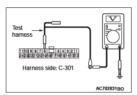
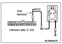
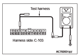
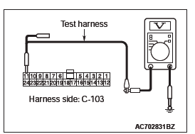
STEP 12. Check the wiring harness between joint connector (CAN1) C-103 and combination meter connector C-03 for a short to power supply. Measure the voltage at joint connector (CAN1) C-103.
CAUTION A digital multimeter should be used. CAUTION The test wiring harness should be used.
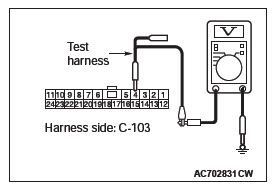
(1) Disconnect joint connector (CAN1), and measure the voltage at the wiring harness side of joint connector (CAN1).
(2) Turn the ignition switch to the ON position.
(3) Measure the voltage between joint connector (CAN1) terminal 4 and body ground.
OK: 4.7 volts or less
(4) Measure the voltage between joint connector (CAN1) terminal 15 and body ground.
OK: 4.7 volts or less
Q: Do all the voltages measure 4.7 volts or less?
YES (vehicles with KOS) : Go to Step 13.
YES (vehicles with WCM) : Go to Step 14.
NO (vehicles with KOS and WCM) : Go to Step 22.
STEP 13. Check the wiring harness between joint connector (CAN1) C-103 and KOS-ECU connector C-102 for a short to power supply. Measure the voltage at joint connector (CAN1) C-103.
CAUTION A digital multimeter should be used. CAUTION The test wiring harness should be used.
(1) Disconnect joint connector (CAN1), and measure the voltage at the wiring harness side of joint connector (CAN1).
(2) Turn the ignition switch to the ON position.
(3) Measure the voltage between joint connector (CAN1) terminal 8 and body ground.
OK: 4.7 volts or less
(4) Measure the voltage between joint connector (CAN1) terminal 21 and body ground.
OK: 4.7 volts or less
Q: Do all the voltages measure 4.7 volts or less?
YES : Go to Step 15.
NO : Go to Step 23.
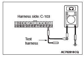
STEP 14. Check the wiring harness between joint connector (CAN1) C-103 and WCM connector C-29 for a short to power supply. Measure the voltage at joint connector (CAN1) C-103.
CAUTION A digital multimeter should be used.
CAUTION The test wiring harness should be used.
(1) Disconnect joint connector (CAN1), and measure the voltage at the wiring harness side of joint connector (CAN1).
(2) Turn the ignition switch to the ON position.
(3) Measure the voltage between joint connector (CAN1) terminal 5 and body ground.
OK: 4.7 volts or less

(4) Measure the voltage between joint connector (CAN1) terminal 16 and body ground.
OK: 4.7 volts or less
Q: Do all the voltages measure 4.7 volts or less?
YES : Go to Step 15.
NO : Go to Step 24.
STEP 15. Check the wiring harness between joint connector (CAN1) C-103 and SRS-ECU connector C-28 for a short to power supply. Measure the voltage at joint connector (CAN1) C-103.
CAUTION A digital multimeter should be used. CAUTION The test wiring harness should be used.
(1) Disconnect joint connector (CAN1), and measure the voltage at the wiring harness side of joint connector (CAN1).
(2) Turn the ignition switch to the ON position.
(3) Measure the voltage between joint connector (CAN1) terminal 2 and body ground.
OK: 4.7 volts or less
(4) Measure the voltage between joint connector (CAN1) terminal 13 and body ground.
OK: 4.7 volts or less
Q: Do all the voltages measure 4.7 volts or less?
YES : Go to Step 16.
NO : Go to Step 25.
STEP 16. Check the wiring harness between joint connector (CAN1) C-103 and occupant classification-ECU connector D-34-2 for a short to power supply. Measure the voltage at joint connector (CAN1) C-103.
CAUTION A digital multimeter should be used.
CAUTION The test wiring harness should be used.
(1) Disconnect joint connector (CAN1), and measure the voltage at the wiring harness side of joint connector (CAN1).
(2) Turn the ignition switch to the ON position.
(3) Measure the voltage between joint connector (CAN1) terminal 11 and body ground.
OK: 4.7 volts or less
(4) Measure the voltage between joint connector (CAN1) terminal 24 and body ground.
OK: 4.7 volts or less
Q: Do all the voltages measure 4.7 volts or less?
YES : Go to Step 17.
NO : Go to Step 26.
STEP 17. Check the wiring harness between joint connector (CAN1) C-103 and A/C-ECU connector C-109 for a short to power supply. Measure the voltage at joint connector (CAN1) C-103.
CAUTION A digital multimeter should be used. CAUTION The test wiring harness should be used.
(1) Disconnect joint connector (CAN1), and measure the voltage at the wiring harness side of joint connector (CAN1).
(2) Turn the ignition switch to the ON position.
(3) Measure the voltage between joint connector (CAN1) terminal 9 and body ground.
OK: 4.7 volts or less
(4) Measure the voltage between joint connector (CAN1) terminal 22 and body ground.
OK: 4.7 volts or less
Q: Do all the voltages measure 4.7 volts or less?
YES (vehicles without MMCS) : Go to Step 18.
YES (vehicles with MMCS) : Go to Step 19.
NO : Go to Step 27.
STEP 18. Check the wiring harness between joint connector (CAN1) C-103 and radio and CD player or radio and CD changer connector C-16 for a short to power supply. Measure the voltage at joint connector (CAN1) C-103.
CAUTION A digital multimeter should be used. CAUTION The test wiring harness should be used.
(1) Disconnect joint connector (CAN1), and measure the voltage at the wiring harness side of joint connector (CAN1).
(2) Turn the ignition switch to the ON position.
(3) Measure the voltage between joint connector (CAN1) terminal 10 and body ground.
OK: 4.7 volts or less
(4) Measure the voltage between joint connector (CAN1) terminal 23 and body ground.
OK: 4.7 volts or less
Q: Do all the voltages measure 4.7 volts or less?
YES (vehicles without satellite radio) : Go to Step 21.
YES (vehicles with satellite radio) : Go to Step 20.
NO : Go to Step 28.
STEP 19. Check the wiring harness between joint connector (CAN1) C-103 and CAN box unit connector C-13 for a short to power supply. Measure the voltage at joint connector (CAN1) C-103.
CAUTION A digital multimeter should be used. CAUTION The test wiring harness should be used.
(1) Disconnect joint connector (CAN1), and measure the voltage at the wiring harness side of joint connector (CAN1).
(2) Turn the ignition switch to the ON position.
(3) Measure the voltage between joint connector (CAN1) terminal 10 and body ground.
OK: 4.7 volts or less
(4) Measure the voltage between joint connector (CAN1) terminal 23 and body ground.
OK: 4.7 volts or less
Q: Do all the voltages measure 4.7 volts or less?
YES (vehicles without satellite radio) : Go to Step 21.
YES (vehicles with satellite radio) : Go to Step 20.
NO : Go to Step 29.
STEP 20. Check the wiring harness between joint connector (CAN1) C-103 and satellite radio tuner connector C-111 for a short to power supply. Measure the voltage at joint connector (CAN1) C-103.
CAUTION A digital multimeter should be used. CAUTION The test wiring harness should be used.
(1) Disconnect joint connector (CAN1), and measure the voltage at the wiring harness side of joint connector (CAN1).
(2) Turn the ignition switch to the ON position.
(3) Measure the voltage between joint connector (CAN1) terminal 3 and body ground.
OK: 4.7 volts or less
(4) Measure the voltage between joint connector (CAN1) terminal 14 and body ground.
OK: 4.7 volts or less
Q: Do all the voltages measure 4.7 volts or less?
YES : Go to Step 21.
NO : Go to Step 30.
STEP 21. Check the wiring harness between joint connector (CAN1) C-103 and ETACS-ECU connector C-301 for a short to power supply. Measure the voltage at joint connector (CAN1) C-103.
CAUTION A digital multimeter should be used. CAUTION The test wiring harness should be used.
(1) Disconnect joint connector (CAN1) and ETACS-ECU connector C-301, and measure the voltage at the wiring harness side of joint connector (CAN1).
(2) Turn the ignition switch to the ON position.
(3) Measure the voltage between joint connector (CAN1) terminal 6 and body ground.
OK: 1.0 volts or less
(4) Measure the voltage between joint connector (CAN1) terminal 19 and body ground.
OK: 1.0 volts or less
Q: Do all the voltages measure 1.0 volts or less?
YES : Go to Step 31.
NO : Repair the wiring harness between joint connector (CAN1) C-103 and ETACS-ECU connector C-301.
STEP 22. Using scan tool MB991958, diagnose the CAN bus line. (checking the combination meter for internal failure).
CAUTION Strictly observe the specified wiring harness repair procedure.
CAUTION To prevent damage to scan tool MB991958, always turn the ignition switch to the "LOCK" (OFF) position before connecting or disconnecting scan tool MB991958.
(1) Disconnect combination meter connector C-03.
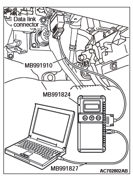
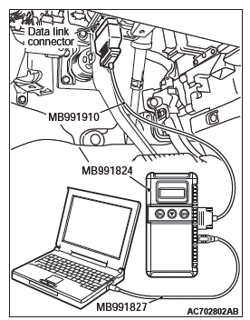
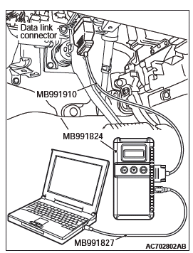
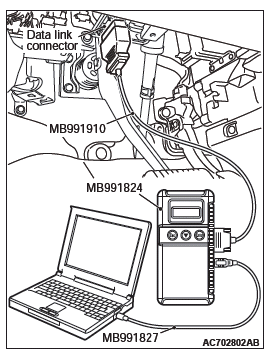
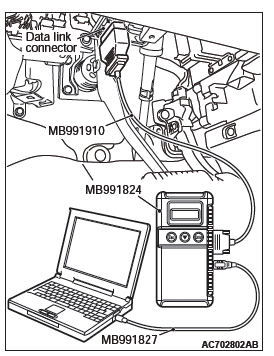
(2) Connect scan tool MB991958 to the data link connector.
(3) Turn the ignition switch to the "ON" position.
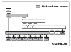
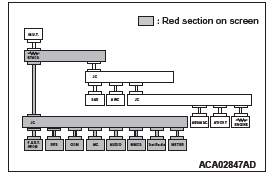
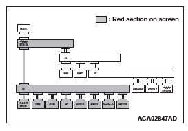
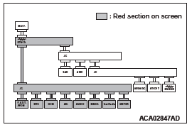
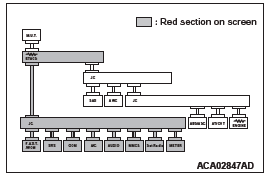
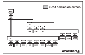
(4) Diagnose CAN bus lines, and check if the scan tool MB991958 screen is as shown in the figure.
OK: The display of the scan tool MB991958 is as shown in the figure.
Q: Does scan tool MB991958 screen correspond to the illustration?
YES : Repair the wiring harness between joint connector (CAN1) C-103 and combination meter connector C-03.
NO : Check combination meter connector C-03, and repair if necessary. If the combination meter connector is in good condition, replace the combination meter.
STEP 23. Using scan tool MB991958, diagnose the CAN bus line. (checking the KOS-ECU for internal failure).
CAUTION Strictly observe the specified wiring harness repair procedure.
CAUTION To prevent damage to scan tool MB991958, always turn the ignition switch to the "LOCK" (OFF) position before connecting or disconnecting scan tool MB991958.
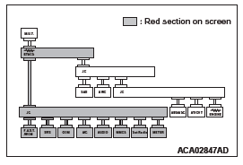
(4) Diagnose CAN bus lines, and check if the scan tool MB991958 screen is as shown in the figure.
OK: The display of the scan tool MB991958 is as shown in the figure.
Q: Does scan tool MB991958 screen correspond to the illustration?
YES : Repair the wiring harness between joint connector (CAN1) C-103 and KOS-ECU connector C-102.
NO : Check KOS-ECU connector C-102, and repair if necessary. If the KOS-ECU connector is in good condition, replace the KOS-ECU.
STEP 24. Using scan tool MB991958, diagnose the CAN bus line. (checking the WCM for internal failure).
CAUTION Strictly observe the specified wiring harness repair procedure.
CAUTION To prevent damage to scan tool MB991958, always turn the ignition switch to the "LOCK" (OFF) position before connecting or disconnecting scan tool MB991958.
(1) Disconnect WCM connector C-29.
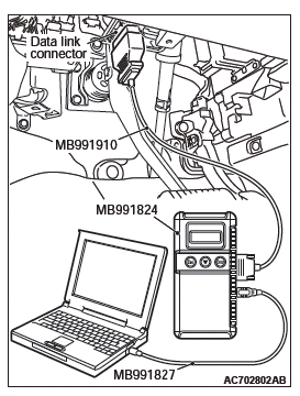
(2) Connect scan tool MB991958 to the data link connector.
(3) Turn the ignition switch to the "ON" position.
(4) Diagnose CAN bus lines, and check if the scan tool MB991958 screen is as shown in the figure.
OK: The display of the scan tool MB991958 is as shown in the figure.
Q: Does scan tool MB991958 screen correspond to the illustration?
YES : Repair the wiring harness between joint connector (CAN1) C-103 and WCM connector C-29.
NO : Check WCM connector C-29, and repair if necessary.
If the WCM connector is in good condition, replace the WCM.
STEP 25. Using scan tool MB991958, diagnose the CAN bus line. (checking the SRS-ECU for internal failure).
CAUTION Strictly observe the specified wiring harness repair procedure.
CAUTION To prevent damage to scan tool MB991958, always turn the ignition switch to the "LOCK" (OFF) position before connecting or disconnecting scan tool MB991958.
(1) Disconnect SRS-ECU connector C-28.
(2) Connect scan tool MB991958 to the data link connector.
(3) Turn the ignition switch to the "ON" position.
(4) Diagnose CAN bus lines, and check if the scan tool MB991958 screen is as shown in the figure.
OK: The display of the scan tool MB991958 is as shown in the figure.
Q: Does scan tool MB991958 screen correspond to the illustration?
YES : Repair the wiring harness between joint connector (CAN1) C-103 and SRS-ECU connector C-28.
NO : Check SRS-ECU connector C-28, and repair if necessary. If the SRS-ECU connector is in good condition, replace the SRS-ECU.
STEP 26. Using scan tool MB991958, diagnose the CAN bus line. (checking the occupant classification-ECU for internal failure).
CAUTION Strictly observe the specified wiring harness repair procedure.
CAUTION To prevent damage to scan tool MB991958, always turn the ignition switch to the "LOCK" (OFF) position before connecting or disconnecting scan tool MB991958.
(1) Disconnect occupant classification-ECU connector D-34-2.
(2) Connect scan tool MB991958 to the data link connector.
(3) Turn the ignition switch to the "ON" position.
(4) Diagnose CAN bus lines, and check if the scan tool MB991958 screen is as shown in the figure.
OK: The display of the scan tool MB991958 is as shown in the figure.
Q: Does scan tool MB991958 screen correspond to the illustration?
YES : Check intermediate connectors C-31 and D-34, and repair if necessary. If the intermediate connector is in good condition, repair the wiring harness between joint connector (CAN1) C-103 and occupant classification-ECU connector D-34-2.
NO : Check occupant classification-ECU connector D-34-2, and repair if necessary. If the occupant classification-ECU connector is in good condition, replace the occupant classification-ECU.
STEP 27. Using scan tool MB991958, diagnose the CAN bus line. (checking the A/C-ECU for internal failure).
CAUTION Strictly observe the specified wiring harness repair procedure.
CAUTION To prevent damage to scan tool MB991958, always turn the ignition switch to the "LOCK" (OFF) position before connecting or disconnecting scan tool MB991958.
(1) Disconnect A/C-ECU connector C-109.
(2) Connect scan tool MB991958 to the data link connector.
(3) Turn the ignition switch to the "ON" position.
(4) Diagnose CAN bus lines, and check if the scan tool MB991958 screen is as shown in the figure.
OK: The display of the scan tool MB991958 is as shown in the figure.
Q: Does scan tool MB991958 screen correspond to the illustration?
YES : Repair the wiring harness between joint connector (CAN1) C-103 and A/C-ECU connector C-109.
NO : Check A/C-ECU connector C-109, and repair if necessary. If the A/C-ECU connector is in good condition, replace the A/C-ECU.
STEP 28. Using scan tool MB991958, diagnose the CAN bus line. (checking the radio and CD player or radio and CD changer for internal failure).
CAUTION Strictly observe the specified wiring harness repair procedure.
CAUTION To prevent damage to scan tool MB991958, always turn the ignition switch to the "LOCK" (OFF) position before connecting or disconnecting scan tool MB991958.
(1) Disconnect radio and CD player or radio and CD changer connector C-16.
(2) Connect scan tool MB991958 to the data link connector.
(3) Turn the ignition switch to the "ON" position.
(4) Diagnose CAN bus lines, and check if the scan tool MB991958 screen is as shown in the figure.
OK: The display of the scan tool MB991958 is as shown in the figure.
Q: Does scan tool MB991958 screen correspond to the illustration?
YES : Repair the wiring harness between joint connector (CAN1) C-103 and radio and CD player or radio and CD changer connector C-16.
NO : Check radio and CD player or radio and CD changer connector C-16, and repair if necessary. If the radio and CD player or radio and CD changer connector is in good condition, replace the radio and CD player or radio and CD changer.
STEP 29. Using scan tool MB991958, diagnose the CAN bus line. (checking the CAN box unit for internal failure) CAUTION Strictly observe the specified wiring harness repair procedure.
CAUTION To prevent damage to scan tool MB991958, always turn the ignition switch to the "LOCK" (OFF) position before connecting or disconnecting scan tool MB991958.
(1) Disconnect CAN box unit connector C-13.
(2) Connect scan tool MB991958 to the data link connector.
(3) Turn the ignition switch to the "ON" position.
(4) Diagnose CAN bus lines, and check if the scan tool MB991958 screen is as shown in the figure.
OK: The display of the scan tool MB991958 is as shown in the figure.
Q: Does scan tool MB991958 screen correspond to the illustration?
YES : Check intermediate connector C-17, and repair if necessary. If the intermediate connector is in good condition, repair the wiring harness between joint connector (CAN1) C-103 and CAN box unit connector C-13.
NO : Check CAN box unit connector C-13, and repair if necessary. If the CAN box unit connector is in good condition, replace the CAN box unit.
STEP 30. Using scan tool MB991958, diagnose the CAN bus line. (checking the satellite radio tuner for internal failure).
CAUTION Strictly observe the specified wiring harness repair procedure.
CAUTION To prevent damage to scan tool MB991958, always turn the ignition switch to the "LOCK" (OFF) position before connecting or disconnecting scan tool MB991958.
(1) Disconnect satellite radio tuner connector C-111.
(2) Connect scan tool MB991958 to the data link connector.
(3) Turn the ignition switch to the "ON" position.
(4) Diagnose CAN bus lines, and check if the scan tool MB991958 screen is as shown in the figure.
OK: The display of the scan tool MB991958 is as shown in the figure.
Q: Does scan tool MB991958 screen correspond to the illustration?
YES : Repair the wiring harness between joint connector (CAN1) C-103 and satellite radio tuner connector C-111.
NO : Check satellite radio tuner connector C-111, and repair if necessary. If the satellite radio tuner connector is in good condition, replace the satellite radio tuner.
STEP 31. Using scan tool MB991958, diagnose the CAN bus line. (trouble symptom check).
CAUTION Strictly observe the specified wiring harness repair procedure.
CAUTION To prevent damage to scan tool MB991958, always turn the ignition switch to the "LOCK" (OFF) position before connecting or disconnecting scan tool MB991958.
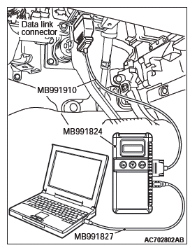
(1) Connect scan tool MB991958 to the data link connector.
(2) Turn the ignition switch to the "ON" position.
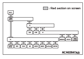
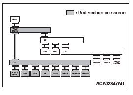
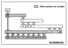
(3) Diagnose CAN bus lines, and check if the scan tool MB991958 screen is as shown in the figure.
OK: The display of the scan tool MB991958 is as shown in the figure.
Q: Does scan tool MB991958 screen correspond to the illustration?
YES : The trouble can be an intermittent malfunction.
NO : Check the ETACS-ECU connector C-301, and repair if necessary. If the ETACS-ECU connector is in good condition, replace the ETACS-ECU.
DIAGNOSTIC ITEM 25: Diagnose the ETACS-ECU, joint connector (CAN1) or lines between ETACS-ECU and joint connector (CAN1).
CAUTION When servicing a CAN bus line, ground yourself by touching a metal object such as an unpainted water pipe. If you fail to do so, a component connected to the CAN bus line may be damaged.
CAN Communication Circuit
FUNCTION
If a failure is present in the wiring harness wires between the ETACS-ECU connector, the joint connector (CAN1), the ETACS-ECU connector and the joint connector (CAN1), this diagnosis result will be set.
TROUBLE JUDGMENT CONDITIONS
If a communication flag is set for none of the ECUs on the CAN-B line, the ETACS-ECU determines that there is a failure.
TROUBLESHOOTING HINTS
- Malfunction of the connector [joint connector (CAN1) or ETACS-ECU connector improperly connected]
- Malfunction of the wiring harness [open circuit between the ETACS-ECU connector and the joint connector (CAN1) ]
- Malfunction of the ETACS-ECU
DIAGNOSIS
Required Special Tools:
- MB991223: Harness Set
- MB992006: Extra Fine Probe
STEP 1. Check joint connector (CAN1) C-103 and EATCS-ECU connector C-301 for loose, corroded or damaged terminals, or terminals pushed back in the connector.
CAUTION The strand end of the twisted wire should be within 10 cm (4 inches) from the connector.
Q: Are joint connector (CAN1) C-103 and ETACS-ECU connector C-301 in good condition?
YES : Go to Step 2.
NO : Repair the damaged parts.
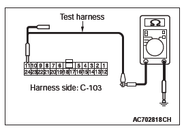
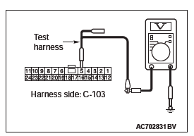
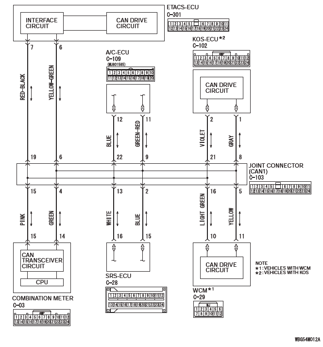
STEP 2. Check the wiring harness between joint connector (CAN1) C-103 and ETACS-ECU connector C-301 for open circuit.
CAUTION Strictly observe the specified wiring harness repair procedure.
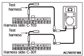
(1) Disconnect joint connector (CAN1) C-103 and ETACS-ECU connector C-301, and check the wiring harness.
(2) Check the wiring harness between joint connector (CAN1) C-103 (terminal 6) and ETACS-ECU connector C-301 (terminal 6) OK: Continuity exists (2 ohms or less)
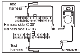
(3) Check the wiring harness between joint connector (CAN1) C-103 (terminal 19) and ETACS-ECU connector C-301 (terminal 7)
OK: Continuity exists (2 ohms or less)
Q: Is the wiring harness between joint connector (CAN1) C-103 and ETACS-ECU connector C-301 in good condition?
YES : Go to Step 3.
NO : Repair the wiring harness between joint connector (CAN1) C-103 and ETACS-ECU connector C-301.
STEP 3. Using scan tool MB991958, diagnose the CAN bus line. (trouble symptom check).
CAUTION Strictly observe the specified wiring harness repair procedure.
CAUTION To prevent damage to scan tool MB991958, always turn the ignition switch to the "LOCK" (OFF) position before connecting or disconnecting scan tool MB991958.
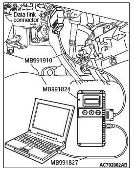
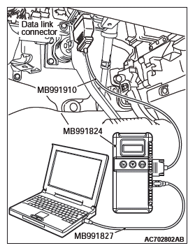
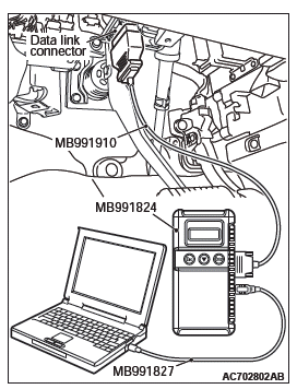
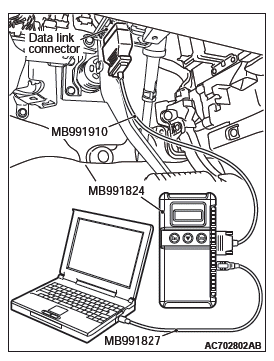
(1) Connect scan tool MB991958 to the data link connector.
(2) Turn the ignition switch to the "ON" position.
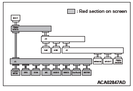
(3) Diagnose CAN bus lines, and check if the scan tool MB991958 screen is as shown in the figure.
OK: The display of the scan tool MB991958 is as shown in the figure.
Q: Does scan tool MB991958 screen correspond to the illustration?
YES : The trouble can be an intermittent malfunction (Refer to GROUP 00, How to use Troubleshooting/inspection Service Points − How to Cope with Intermittent Malfunction).
NO : Replace the ETACS-ECU.
READ NEXT:
 Diagnostic Item 26
DIAGNOSTIC ITEM 26: Short to power supply or ground, open circuit or
line-to-line short in the
CAN-B bus lines.
CAUTION
When servicing a CAN bus line, ground yourself by touching a metal object such
General Information, Specifications
General Information
The blower, heater, and evaporator have been integrated
with the heater and A/C system to achieve
greater fan power and noise reduction.
SAFETY PRECAUTIONS
WARNING
Wear safety gog
SEE MORE:
Liftgate
GENERAL INFORMATION
LIFTGATE OPENER CONTROL FUNCTION
When the liftgate lock release handle is operated to
open the liftgate (the liftgate lock release handle
open switch turns ON) while the vehicle is parked,
ETACS-ECU turns the unlock relay output ON for 0.3
second, thus the liftgate can be opene
DTC B1B78, B1B79, B1B7A, B1B7D, B1B7E, B1B7F, B1B82, B1B83, B1B84, B1B87,
B1B88, B1B89, B1B8C, B1B8D, B1B8E, B1B91, B1BA7, B1BA8
DTC B1B78: Passenger Seat Weight Sensor (front: LH) Performance
DTC B1B7D: Passenger Seat Weight Sensor (front: RH) Performance
DTC B1B82: Passenger Seat Weight Sensor (rear: LH) Performance
DTC B1B87: Passenger Seat Weight Sensor (rear: RH) Performance
CAUTION
If DTC B1B78, B1B7D, B1B82 or B1B87
