Mitsubishi Outlander: Liftgate
GENERAL INFORMATION
LIFTGATE OPENER CONTROL FUNCTION
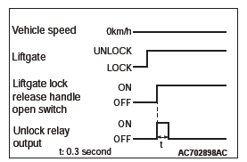
When the liftgate lock release handle is operated to open the liftgate (the liftgate lock release handle open switch turns ON) while the vehicle is parked, ETACS-ECU turns the unlock relay output ON for 0.3 second, thus the liftgate can be opened by the liftgate lock release handle.
SEALANT
LIFTGATE DIAGNOSIS
INTRODUCTION TO LIFTGATE DIAGNOSIS
Difficult locking/unlocking, uneven clearance, and wind noise from the liftgate may be due to improper adjustment of the liftgate.
LIFTGATE DIAGNOSTIC TROUBLESHOOTING STRATEGY
Use these steps to plan your diagnostic strategy. If you follow them carefully, you will be sure that you have exhausted most of the possible ways to find a liftgate fault.
1. Gather information from the customer.
2. Verify that the condition described by the customer exists.
3. Find the malfunction by following the Symptom Chart.
4. Verify malfunction is eliminated.
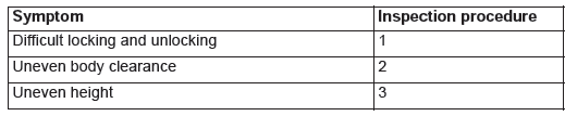
SYMPTOM CHART
SYMPTOM PROCEDURES
INSPECTION PROCEDURE 1: Difficult Locking and Unlocking
DIAGNOSIS
STEP 1. Check the engagement of the liftgate latch and liftgate striker.
Q: Are the liftgate latch and liftgate striker engaged correctly?
YES : Then go to Step 2.
NO : Align the liftgate latch and liftgate striker.
STEP 2. Retest the system.
Q: Does the liftgate lock operate normally?
YES : The procedure is complete.
NO : Return to Step 1.
INSPECTION PROCEDURE 2: Uneven Body Clearance
DIAGNOSIS
STEP 1. Check the clearance around the liftgate.
Q: Is the liftgate installed correctly?
YES : Go to Step 2.
NO : Adjust clearance around liftgate .
STEP 2. Retest the system.
Q: Is the clearance around the liftgate even?
YES : The procedure is complete.
NO : Return to Step 1.
INSPECTION PROCEDURE 3: Uneven Height
DIAGNOSIS
STEP 1. Check the liftgate damper height.
Q: Is the liftgate damper height proper?
YES : Go to Step 2.
NO : Adjust the liftgate damper. Then go to Step2.
STEP 2. Retest the system.
Q: Is the height between the liftgate and body panels even?
YES : The procedure is complete.
NO : Return to Step 1.
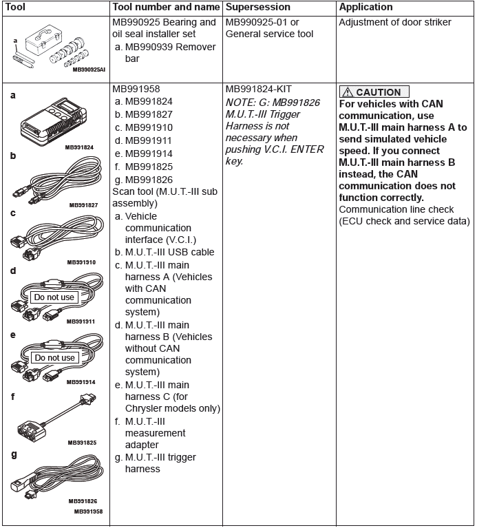
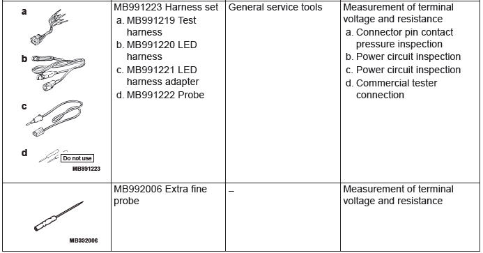
SPECIAL TOOL
ON-VEHICLE SERVICE
LIFTGATE ALIGNMENT
Required Special Tool:
- MB990939: Remover Bar
LIFTGATE UPPER ALIGNMENT
- If the striker is not engaged with the latch properly, adjust by loosening the striker mounting screws.
- If the clearance between the liftgate and the body is uneven, loosen the liftgate-side liftgate hinge mounting bolts to adjust it.
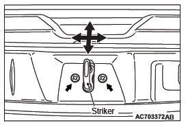
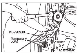
LIFTGATE LOWER ALIGNMENT
If the striker does not engage with the latch properly, remove the quarter trim lower (Refer to GROUP 52A - Interior Trim). Replace the striker mounting screws with temporary bolts, and use the special tool (remover bar MB990939) and a hammer to tap the bolt head in the desired direction to adjust the striker position.
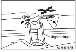
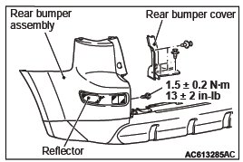
If the clearances between the liftgate lower and the body (rear bumper assembly) at left and right are uneven, adjust the liftgate lower as follows.
1. Remove the rear bumper covers and reflectors located at left and right sides of the rear bumper assembly.
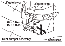
2. Loosen the liftgate hinge mounting bolts as shown in the illustration located at left and right sides of the body, and slide the liftgate lower to adjust its position so that the clearances between the liftgate lower and body (rear bumper assembly) at left and right become even.
3. Tighten the liftgate hinge mounting bolts to the specified torque.
ADJUSTMENT OF LIFTGATE HEIGHT
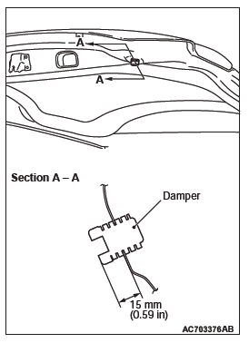
Rotate the damper by using the arrow mark on the damper as a guide to adjust the liftgate height. The damper height is altered by roughly 3 mm (0.12 inch) when the damper is rotated once.
NOTE: If a rattling noise is heard due to the vibration of the liftgate when the vehicle is being driven, adjust the damper height until the damper is seated on the vehicle body. The damper should be seated on the vehicle body regardless of a rattling noise.
LIFTGATE
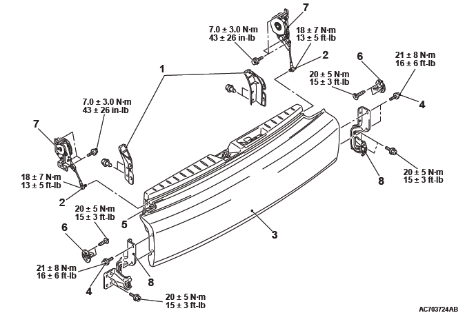
REMOVAL AND INSTALLATION <LIFTGATE UPPER>
Pre-removal operation
- Liftgate spoiler assembly removal
- Liftgate trim assembly removal
- Rear wiper motor removal
Post-installation operation
- Liftgate alignment
- Adjustment of liftgate height
- Rear wiper motor installation
- Liftgate trim assembly installation
- Liftgate spoiler assembly installation
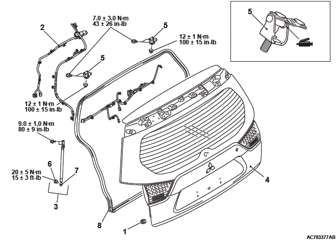
Liftgate upper assembly removal steps
- Damper
- Harness connector
- Rear combination light assembly
- Liftgate gas spring assembly
- Liftgate upper assembly
- Headlining assembly
- Liftgate hinge
- Ball joint
Liftgate opening weatherstrip removal steps
- Liftgate gas spring ball joint connection
- Liftgate opening weatherstrip
REMOVAL SERVICE POINT
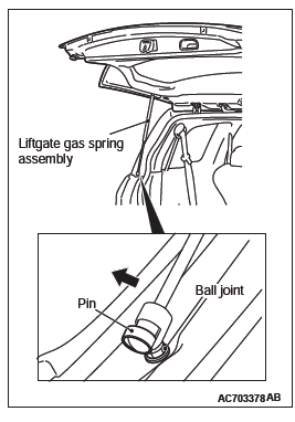
LIFTGATE GAS SPRING ASSEMBLY REMOVAL
CAUTION
- Do not disassemble or throw the liftgate gas spring into the fire.
- Before disposal, make a hole to remove the gas.
- Make sure that the piston rod should not collect any foreign particles.
As shown in the figure, slide the pin and remove the liftgate gas spring assembly from the ball joint in the direction of the arrow.
INSTALLATION SERVICE POINTS
LIFTGATE OPENING WEATHERSTRIP INSTALLATION
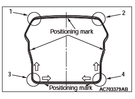
1. The marking on the upper center of the liftgate opening weatherstrip should be positioned at the center of the vehicle body.
2. Install the weatherstrip according to the order shown in the figure.
3. Install the weatherstrip according to the direction shown by the arrow in the figure.
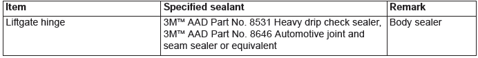
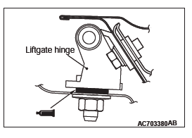
LIFTGATE HINGE INSTALLATION
Apply the specified sealant to the liftgate hinge mounting surface, and install the liftgate hinge.
Specified Sealant: 3M AAD Part No. 8531 Heavy drip check sealer, 3M AAD Part No. 8646 Automotive joint and seam sealer or equivalent
REMOVAL AND INSTALLATION <LIFTGATE LOWER>
Post-installation operation
- Liftgate alignment
Liftgate lower assembly removal steps
- Cover
- Liftgate cable mounting bolt
- Liftgate lower garnish
- Liftgate hinge mounting bolt
- Liftgate lower assembly
Striker removal steps
- Quarter trim lower
- Striker
Liftgate cable removal steps
- Quarter trim lower
- Liftgate cable
Liftgate hinge removal steps
- Cover
- Rear bumper assembly
- Liftgate hinge
INSTALLATION SERVICE POINT
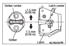
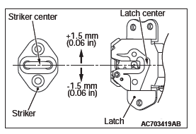
STRIKER INSTALLATION
Install the striker so that the striker center does not deviate more than +-1.5 mm (0.06 inch) from the latch center.
LIFTGATE HANDLE AND LATCH
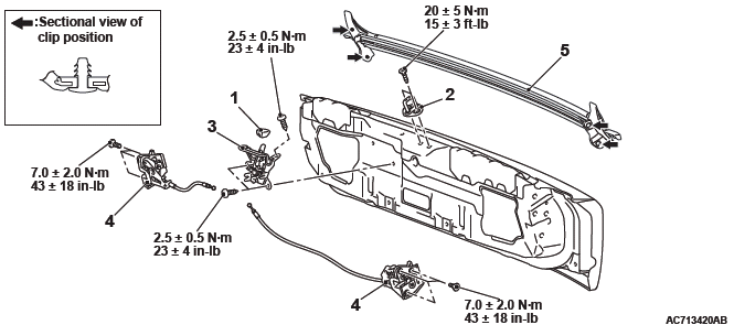
REMOVAL AND INSTALLATION <LIFTGATE UPPER>
Post-installation operation
- Liftgate alignment
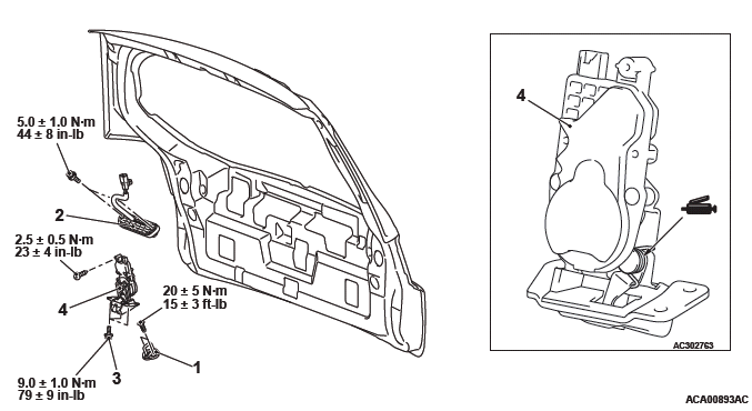
Striker removal steps
- Liftgate trim
- Striker
Liftgate lock release handle removal steps
- Liftgate trim
- Rear wiper motor assembly
- Liftgate lock release handle
Liftgate latch removal steps
- Liftgate trim
- Ground bolt
- Liftgate latch assembly
INSTALLATION SERVICE POINT
STRIKER INSTALLATION
Install the striker so that the striker center does not deviate more than +-1.5 mm (0.06 inch) from the latch center.
INSPECTION
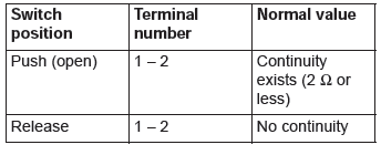
LIFTGATE LOCK RELEASE HANDLE (LIFTGATE OPEN SWITCH) CHECK
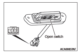
<VEHICLES WITH KOS>
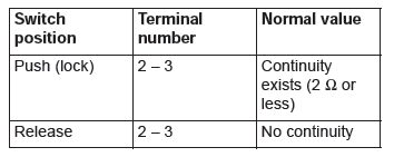
LIFTGATE LOCK RELEASE HANDLE (LIFTGATE LOCK SWITCH) CHECK
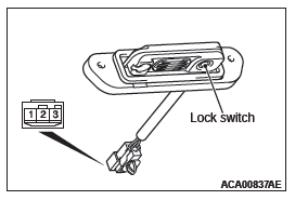
<VEHICLES WITH KOS>
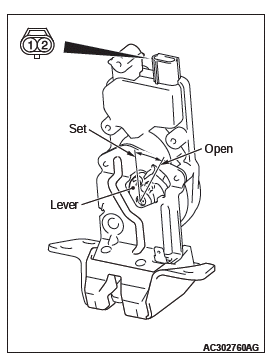
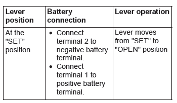
LIFTGATE LOCK ACTUATOR CHECK
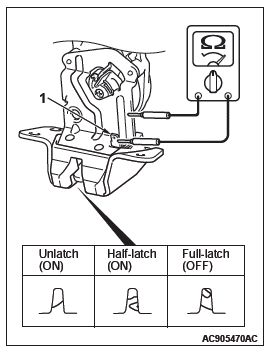
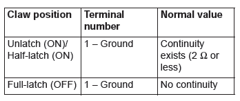
LIFTGATE LATCH SWITCH CHECK
REMOVAL AND INSTALLATION <LIFTGATE LOWER>
Post-installation operation
- Liftgate alignment
Liftgate lock release handle knob removal
- Liftgate lock release handle knob
Striker removal steps
- Liftgate lock release handle knob
- Liftgate lower trim
- Striker
Liftgate latch removal steps
- Liftgate lock release handle knob
- Liftgate lower trim
- Liftgate handle controller
- Liftgate latch
Liftgate weatherstrip removal
- Liftgate weatherstrip
INSTALLATION SERVICE POINTS
LIFTGATE WEATHERSTRIP INSTALLATION
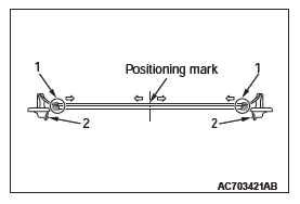
1. The marking on the liftgate weatherstrip should be positioned at the center of the liftgate lower.
2. Install the weatherstrip according to the order shown in the figure.
3. Install the weatherstrip according to the direction shown by the arrow in the figure.
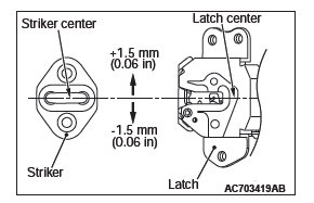
STRIKER INSTALLATION
Install the striker so that the striker center does not deviate more than +-1.5 mm (0.06 in) from the latch center.
READ NEXT:
 Sunroof
SPECIFICATIONS
SERVICE SPECIFICATION
SEALANT
GENERAL INFORMATION
SUNROOF FUNCTION
A motor-driven inner slide-type glass sunroof with a
tilt-up mechanism is available in some models as
optional equip
General Information
NOTE: In this manual, F.A.S.T.-key (Free-hand
Advanced Security Transmitter) is described as Keyless
Operation System (KOS).
The keyless operation system (KOS) enables the
driver to unlock all the doo
SEE MORE:
Balancer Timing Chain, Balancer Shaft and Oil Pump Module
REMOVAL AND INSTALLATION
Pre-removal and Post-installation Operation
Timing Chain Removal and Installation
Removal steps
Timing chain tensioner
Balancer timing chain guide
Balancer timing chain guide
Balancer shaft and oil pump
module
Balancer timing chain
Crankshaft sprocket
Required S
Transfer
DISASSEMBLY AND ASSEMBLY
<Vehicles with S-AWC>
Disassembly steps
Dust seal guard
Oil seal
O-ring
Dust seal
Oil seal
Cover
Transfer
<Vehicles without S-AWC>
Disassembly steps
Dust seal guard
Oil seal
O-ring
Oil seal
Oil seal
Cover
Transfer
Required special tools:
MD
