Mitsubishi Outlander: Sunroof
SPECIFICATIONS
SERVICE SPECIFICATION

SEALANT

GENERAL INFORMATION
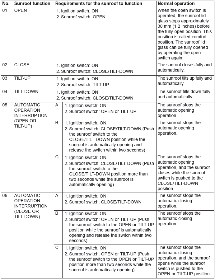
SUNROOF FUNCTION
A motor-driven inner slide-type glass sunroof with a tilt-up mechanism is available in some models as optional equipment. Even when the sunroof is fully closed, a sufficient amount of lighting and a feeling of openness can still be obtained by opening the sunroof sunshade.
SUNROOF TIMER FUNCTION
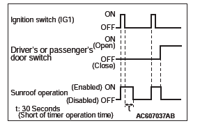
The sunroof ECU (integrated into the sunroof motor assembly) receives the ignition switch (IG1) signal transmitted by ETACS-ECU. If the ignition switch (IG1) signal turns OFF, the sunroof ECU allows the sunroof switch to open/close (timer activation) the sunroof for approximately 30 seconds. During the timer operation, if the driver's or passenger's door open is detected from the door switch signal transmitted by ETACS-ECU, the sunroof timer function stops at this time.
SUNROOF DIAGNOSIS
TROUBLESHOOTING STRATEGY
Refer to GROUP 00, How to Use Troubleshooting/Inspection Service Points, Troubleshooting Contents.
DIAGNOSTIC TROUBLE CODE CHART
CAUTION On troubleshooting, if the ignition switch is turned ON while disconnecting connector(s), diagnostic trouble code(s) associated with other system may be set. On completion, confirm all systems for diagnostic trouble code(s). If diagnostic trouble code(s) are set, erase them all.
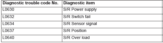
NOTE: S/R: Abbreviation of sunroof
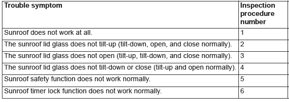
TROUBLE SYMPTOM CHART
CAUTION During diagnosis, a diagnostic trouble code associated with other system may be set when the ignition switch is turned on with connector(s) disconnected. On completion, confirm all systems for diagnostic trouble code(s). If diagnostic trouble code(s) are set, erase them all.
DIAGNOSTIC TROUBLE CODE PROCEDURES
Code No. L0630: S/R Power Supply
CAUTION Before replacing the ECU, ensure that the input and output signal circuits are normal.
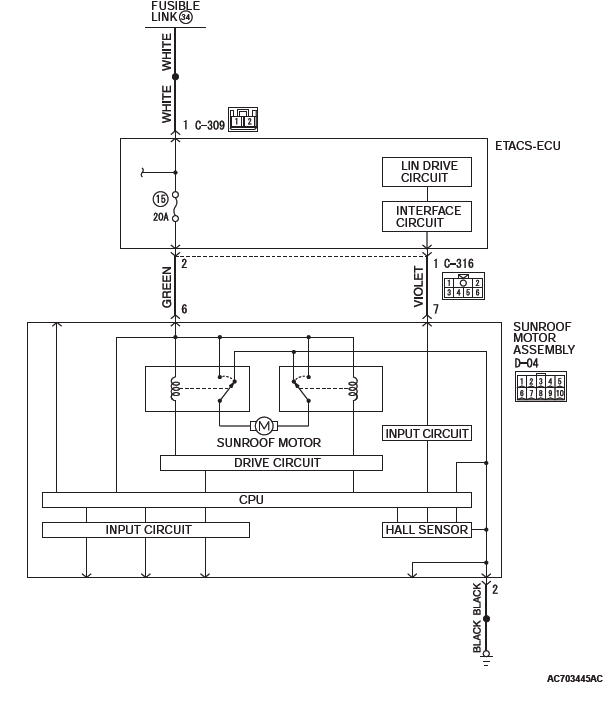
Sunroof Motor Assembly Power Supply Circuit
COMMENTS ON TROUBLE SYMPTOM
When the terminal voltage of the sunroof motor assembly is 8 V or less, or 18 V or more, and if it continues for 60 seconds, the sunroof motor assembly will set the diagnostic trouble code No. L0630.
PROBABLE CAUSES
- Malfunction of the sunroof motor assembly
- Damaged wiring harness and connectors
DIAGNOSTIC PROCEDURE
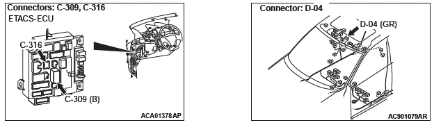
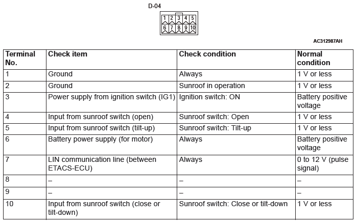
STEP 1. Check sunroof motor assembly connector D-04 for loose, corroded or damaged terminals, or terminals pushed back in the connector.
Q: Is sunroof switch connector D-04 in good condition?
YES : Go to Step 2.
NO : Repair or replace the damaged component(s). Refer to GROUP 00E, Harness Connector Inspection. Check that the sunroof works normally.
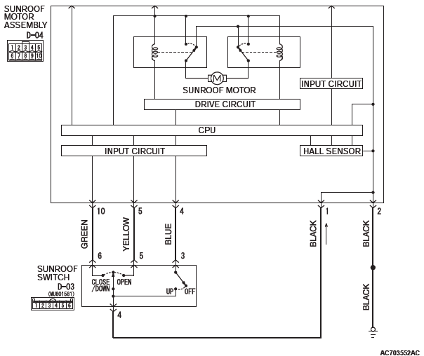
STEP 2. Check the wiring harness between sunroof motor assembly connector D-04 (terminal 6) and fusible link (34).
- Check the power supply line for open circuit and short circuit.
NOTE: Also check ETACS-ECU connectors C-309 and C-316 for loose, corroded, or damaged terminals, or terminals pushed back in the connector. If ETACS-ECU connectors C-309 and C-316 is damaged, repair or replace the damaged component( s) as described in GROUP 00E, Harness Connector Inspection.
Q: Is the wiring harness between sunroof motor assembly connector D-04 (terminal 6) and fusible link (34) in good condition?
YES : Go to Step 3.
NO : The wiring harness may be damaged or the connector(s) may have loose, corroded or damaged terminals, or terminals pushed back in the connector.
Repair the wiring harness as necessary. Check that the sunroof works normally.
STEP 3. Diagnostic trouble code recheck
Recheck if the diagnostic trouble code is set.
- Erase the diagnostic trouble code.
- Turn the ignition switch from the LOCK (OFF) position to the ON position.
- Check if the diagnostic trouble code is set.
Q: Is the diagnostic trouble code set?
YES : Replace the sunroof motor assembly.
NO : The procedure is complete.
Code No. L0632: S/R Switch fall
CAUTION Before replacing the ECU, ensure that the input and output signal circuits are normal.
Sunroof Switch Circuit
COMMENTS ON TROUBLE SYMPTOM
If each switch (UP, OPEN, CLOSE/DOWN) of the sunroof switch is in the ON status for 60 seconds, the sunroof motor assembly will set the diagnostic trouble code No. L0632.
PROBABLE CAUSES
- Malfunction of the sunroof motor assembly
- Malfunction of the sunroof switch
- Damaged wiring harness and connectors
DIAGNOSTIC PROCEDURE
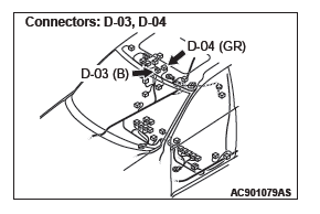
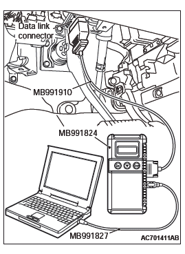
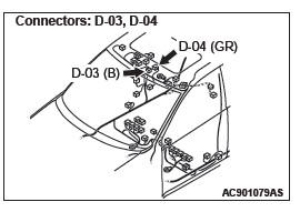
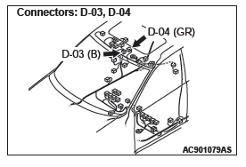
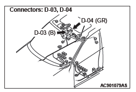
STEP 1. Check sunroof switch connector D-03 and sunroof motor assembly D-04 for loose, corroded or damaged terminals, or terminals pushed back in the connector.
Q: Are sunroof switch connector D-03 and sunroof motor assembly D-04 in good condition?
YES : Go to Step 2.
NO : Repair or replace the damaged component(s). Refer to GROUP 00E, Harness Connector Inspection. Check that the sunroof works normally.
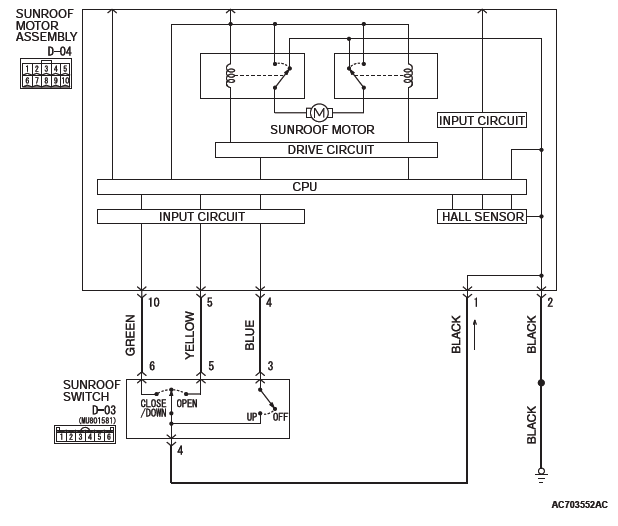
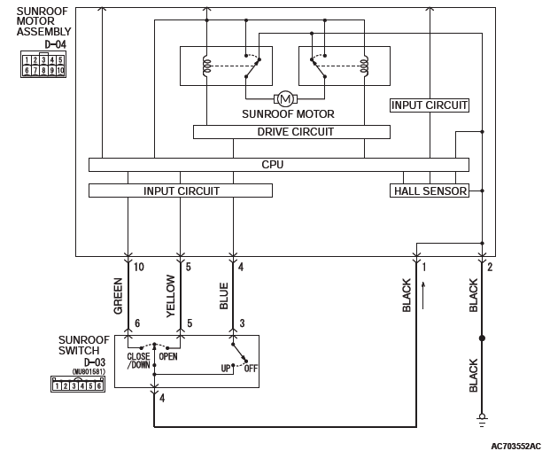
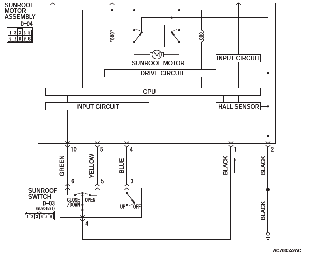
STEP 2. Check the wiring harness between sunroof switch connector D-03 (terminals No. 3, 5, 6) and sunroof motor assembly connector D-04 (terminals No. 4, 5, 10).
- Check the power supply line for open circuit and short circuit.
Q: Is the wiring harness between sunroof switch connector D-03 (terminal 3, 5, 6) and sunroof motor assembly connector D-04 (terminal No. 4, 5, 10) in good condition?
YES : Go to Step 3.
NO : The wiring harness may be damaged or the connector(s) may have loose, corroded or damaged terminals, or terminals pushed back in the connector.
Repair the wiring harness as necessary. Check that the sunroof works normally.
STEP 3. Diagnostic trouble code recheck
Replace the sunroof switch. Recheck if the diagnostic trouble code is set.
- Erase the diagnostic trouble code.
- Turn the ignition switch from the LOCK (OFF) position to the ON position.
- Check if the diagnostic trouble code is set.
Q: Is the diagnostic trouble code set?
YES : Replace the sunroof motor assembly.
NO : The procedure is complete.
Code No. L0634: S/R Sensor signal
CAUTION Before replacing the ECU, ensure that the input and output signal circuits are normal.
COMMENTS ON TROUBLE SYMPTOM
If one of two signals from the sunroof lid glass position detection sensor cannot be detected, the sunroof motor assembly will set the diagnostic trouble code No. L0634.
PROBABLE CAUSES
- Malfunction of the sunroof motor assembly
DIAGNOSTIC PROCEDURE
Diagnostic trouble code recheck
Recheck if the diagnostic trouble code is set.
- Erase the diagnostic trouble code.
- Turn the ignition switch from the LOCK (OFF) position to the ON position.
- Check if the diagnostic trouble code is set.
Q: Is the diagnostic trouble code set?
YES : Replace the sunroof motor assembly.
NO : The procedure is complete.
Code No. L0637 S/R Position
CAUTION Before replacing the ECU, ensure that the input and output signal circuits are normal.
COMMENTS ON TROUBLE SYMPTOM
If the roof lid glass position is out of the specified range, ETACS-ECU will set the diagnostic trouble code No. L0637.
PROBABLE CAUSES
- Malfunction of the sunroof motor assembly
DIAGNOSTIC PROCEDURE
STEP 1. Check the sunroof fully closed position
- Carry out the learning procedures of the sunroof fully closed position.
- Recheck if the diagnostic trouble code is set.
- Erase the diagnostic trouble code.
- Turn the ignition switch from the LOCK (OFF) position to the ON position.
- Check if the diagnostic trouble code is set.
Q: Is the check result normal?
YES : The procedure is complete.
NO : Go to Step 2.
STEP 2. Diagnostic trouble code recheck
Recheck if the diagnostic trouble code is set.
- Erase the diagnostic trouble code.
- Turn the ignition switch from the LOCK (OFF) position to the ON position.
- Check if the diagnostic trouble code is set.
Q: Is the diagnostic trouble code set?
YES : Replace the sunroof motor assembly.
NO : The procedure is complete.
Code No. L0640 S/R Over load
CAUTION Before replacing the ECU, ensure that the input and output signal circuits are normal.
COMMENTS ON TROUBLE SYMPTOM
If the over load (foreign material pinched) is detected consecutively five times during a sunroof operation, ETACS-ECU will set the diagnostic trouble code No.
L0640.
PROBABLE CAUSES
- Malfunction of the sunroof motor assembly
DIAGNOSTIC PROCEDURE
STEP 1. Check the sunroof fully closed position
- Carry out the learning procedures of the sunroof fully closed position.
- Recheck if the diagnostic trouble code is set.
- Erase the diagnostic trouble code.
- Turn the ignition switch from the LOCK (OFF) position to the ON position.
- Check if the diagnostic trouble code is set.
Q: Is the check result normal?
YES : The procedure is complete.
NO : Go to Step 2.
STEP 2. Diagnostic trouble code recheck
Recheck if the diagnostic trouble code is set.
- Erase the diagnostic trouble code.
- Turn the ignition switch from the LOCK (OFF) position to the ON position.
- Check if the diagnostic trouble code is set.
Q: Is the diagnostic trouble code set?
YES : Replace the sunroof motor assembly.
NO : The procedure is complete.
SYMPTOM PROCEDURES
INSPECTION PROCEDURE 1: Sunroof does not Work at All.
CAUTION Before replacing the ECU, ensure that the power supply circuit, the ground circuit and the communication circuit are normal.
Sunroof Motor Assembly Power Supply Circuit
CIRCUIT OPERATION
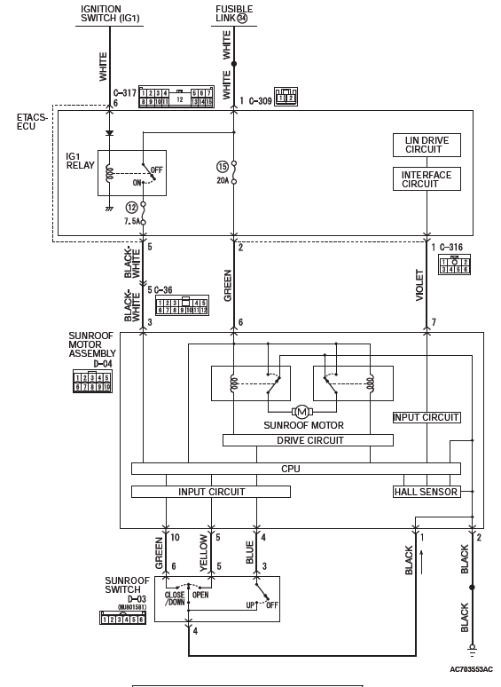
- The sunroof motor assembly is energized through fusible link (34) by the battery.
- When the ignition switch (IG1) signal is on, the sunroof motor assembly is ready to operate.
TROUBLESHOOTING HINTS
- The sunroof switch may be defective
- The sunroof motor assembly may be defective
- The wiring harness or connectors may have loose, corroded, or damaged terminals, or terminals pushed back in the connector
DIAGNOSTIC PROCEDURE
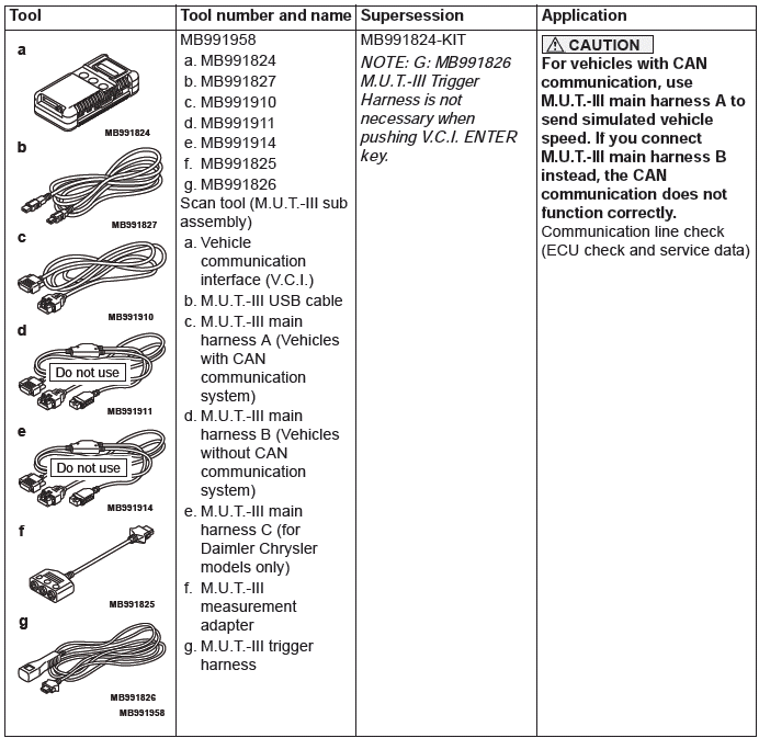
Required Special Tools:
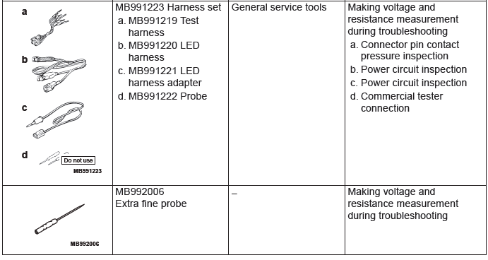
- MB992006: Extra fine probe
- MB991223: Harness set
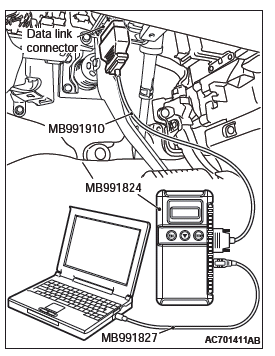
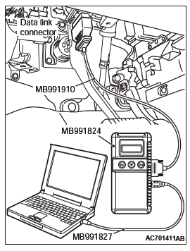
- MB991958: Scan Tool (M.U.T.-III Sub Assembly)
- MB991824: Vehicles Communication Interface (V.C.I.)
- MB991827: M.U.T.-III USB Cable
- MB991910: M.U.T.-III Main Harness A (Vehicles with CAN communication system)
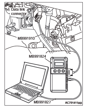
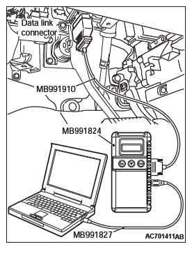
STEP 1. Using scan tool MB991958, read the diagnostic trouble code.
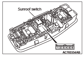
CAUTION To prevent damage to scan tool MB991958, always turn the ignition switch to the "LOCK" (OFF) position before connecting or disconnecting scan tool MB991958.
- Connect scan tool MB991958. Refer to GROUP 42B, "How to connect scan tool (M.U.T.-III)".
- Turn the ignition switch to the "ON" position.
- Check whether the ETACS-ECU related DTC is set.
- Turn the ignition switch to the "LOCK" (OFF) position.
Q: Is the DTC set?
YES : Diagnose the ETACS-ECU.
NO : Go to Step 2.
STEP 2. Check sunroof switch connector D-03 for loose, corroded or damaged terminals, or terminals pushed back in the connector.
Q: Is sunroof switch connector D-03 in good condition?
YES : Go to Step 3.
NO : Repair or replace the damaged component(s). Refer to GROUP 00E, Harness Connector Inspection. Check that the sunroof works normally.
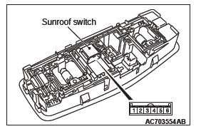
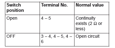
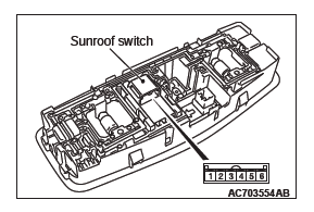
STEP 3. Sunroof switch check
- Remove the sunroof switch.
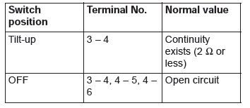
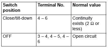
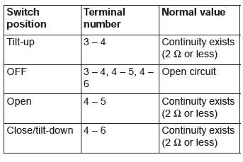
- Check continuity when the sunroof switch is operated to "OPEN", "TILT-UP" or "CLOSE/TILT-DOWN" position.
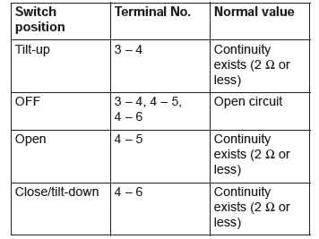
Q: Is the sunroof switch normal?
YES : Go to Step 4.
NO : Replace the sunroof switch. Check that the sunroof works normally.
STEP 4. Check the ground circuit to the sunroof motor assembly. Measure the resistance at sunroof switch connector D-03.
- Disconnect sunroof switch connector D-03 and measure the resistance available at the wiring harness side of the connector.
- Measure the resistance value between terminal 4 and ground.
- The resistance should be 2 ohms or less.
Q: Is the measured resistance 2 ohms or less?
YES : Go to Step 7.
NO : Go to Step 5.
STEP 5. Check sunroof motor assembly connector D-04 for loose, corroded or damaged terminals, or terminals pushed back in the connector.
Q: Is sunroof motor assembly connector D-04 in good condition?
YES : Go to Step 6.
NO : Repair or replace the damaged component(s). Refer to GROUP 00E, Harness Connector Inspection. Check that the sunroof works normally.
STEP 6. Check the wiring harness between sunroof switch connector D-03 (terminal No. 4) and sunroof motor assembly connector D-04 (terminal No. 1).
- Check the power supply line for open circuit and short circuit.
Q: Is the wiring harness between sunroof switch connector D-03 (terminal 4) and sunroof motor assembly connector D-04 (terminal No. 1) in good condition?
YES : No action is necessary and testing is complete.
NO : The wiring harness may be damaged or the connector(s) may have loose, corroded or damaged terminals, or terminals pushed back in the connector.
Repair the wiring harness as necessary. Check that the sunroof works normally.
STEP 7. Check sunroof motor assembly connector D-04 for loose, corroded or damaged terminals, or terminals pushed back in the connector.
Q: Is sunroof motor assembly connector D-04 in good condition?
YES : Go to Step 8.
NO : Repair or replace the damaged component(s). Refer to GROUP 00E, Harness Connector Inspection. Check that the sunroof works normally.
STEP 8. Check the wiring harness between sunroof switch connector D-03 (terminal No. 4) and sunroof motor assembly connector D-04 (terminal No. 1).
- Check the power supply line for open circuit and short circuit.
Q: Is the wiring harness between sunroof switch connector D-03 (terminal 4) and sunroof motor assembly connector D-04 (terminal No. 1) in good condition?
YES : Go to Step 9.
NO : The wiring harness may be damaged or the connector(s) may have loose, corroded or damaged terminals, or terminals pushed back in the connector.
Repair the wiring harness as necessary. Check that the sunroof works normally.
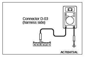
STEP 9. Check the ground circuit to the sunroof motor assembly. Measure the resistance at sunroof motor assembly connector D-04.
- Disconnect sunroof motor assembly connector D-04 and measure the resistance available at the wiring harness side of the connector.
- Measure the resistance value between terminal 2 and ground.
- The resistance should be 2 ohms or less.
Q: Is the measured resistance 2 ohms or less?
YES : Go to Step 11.
NO : Go to Step 10.
STEP 10. Check the wiring harness between sunroof motor assembly connector D-04 (terminal 2) and ground.
- Check the power supply line for open circuit and short circuit.
Q: Is the wiring harness between sunroof motor assembly connector D-04 (terminal 2) and ground in good condition?
YES : No action is necessary and testing is complete.
NO : The wiring harness may be damaged or the connector(s) may have loose, corroded or damaged terminals, or terminals pushed back in the connector.
Repair the wiring harness as necessary. Check that the sunroof works normally.
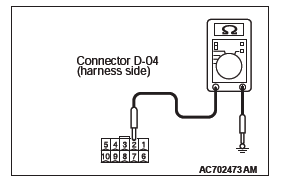
STEP 11. Check the fusible link (34) line of power supply circuit to the sunroof motor assembly. Measure the voltage at sunroof motor assembly connector D-04.
- Disconnect sunroof motor assembly connector D-04 and measure the voltage available at the wiring harness side of the connector.
- Measure the voltage between terminal 6 and ground.
- The voltage should measure approximately 12 volts (battery positive voltage).
Q: Is the measured voltage approximately 12 volts (battery positive voltage)?
YES : Go to Step 13.
NO : Go to Step 12.
STEP 12. Check the wiring harness between sunroof motor assembly connector D-04 (terminal 6) and fusible link (34).
- Check the power supply line for open circuit and short circuit.
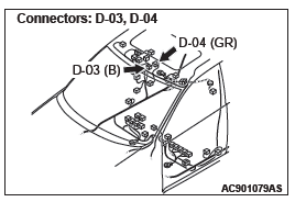
NOTE: Also check ETACS-ECU connectors C-309 and C-316 for loose, corroded, or damaged terminals, or terminals pushed back in the connector. If ETACS-ECU connectors C-309 and C-316 is damaged, repair or replace the damaged component( s) as described in GROUP 00E, Harness Connector Inspection.
Q: Is the wiring harness between sunroof motor assembly connector D-04 (terminal 6) and fusible link (34) in good condition?
YES : No action is necessary and testing is complete.
NO : The wiring harness may be damaged or the connector(s) may have loose, corroded or damaged terminals, or terminals pushed back in the connector.
Repair the wiring harness as necessary. Check that the sunroof works normally.
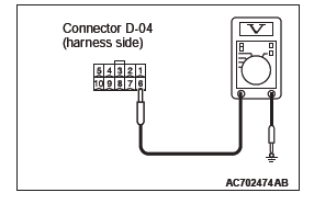
STEP 13. Check the ignition switch (IG1) circuit to the sunroof motor assembly. Measure the voltage at sunroof motor assembly connector D-04.
- Disconnect sunroof motor assembly connector D-04 and measure the voltage available at the wiring harness side of the connector.
- Turn the ignition switch to the "ON" position.
- Measure the voltage between terminal 3 and ground.
- The voltage should measure approximately 12 volts (battery positive voltage).
Q: Is the measured voltage approximately 12 volts (battery positive voltage)?
YES : Go to Step 16.
NO : Go to Step 14.
STEP 14. Check the wiring harness between sunroof motor assembly connector D-04 (terminal 3) and ETACS-ECU connector C-317 (terminal 5).
- Check the power supply line for open circuit and short circuit.
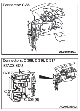
NOTE: Also check intermediate connector C-36 for loose, corroded, or damaged terminals, or terminals pushed back in the connector. If intermediate connector C-36 is damaged, repair or replace the damaged component(s) as described in GROUP 00E, Harness Connector Inspection.
Q: Is the wiring harness between sunroof motor assembly connector D-04 (terminal 3) and ETACS-ECU connector C-317 (terminal 5) in good condition?
YES : Go to Step 15.
NO : The wiring harness may be damaged or the connector(s) may have loose, corroded or damaged terminals, or terminals pushed back in the connector.
Repair the wiring harness as necessary. Check that the sunroof works normally.
STEP 15. Check the wiring harness between ETACS-ECU connector C-317 (terminal 6) and ignition switch (IG1).
- Check the power supply line for open circuit and short circuit.
Q: Is the wiring harness between sunroof motor assembly connector D-04 (terminal 3) and the ignition switch (IG1) in good condition?
YES : Go to Step 16.
NO : The wiring harness may be damaged or the connector(s) may have loose, corroded or damaged terminals, or terminals pushed back in the connector.
Repair the wiring harness as necessary. Check that the sunroof works normally.
STEP 16. Retest the system.
Check that the sunroof works normally.
Q: Is the check result normal?
YES : No action is necessary and testing is complete.
NO : Replace the sunroof motor assembly. Check that the sunroof works normally.
INSPECTION PROCEDURE 2: The Sunroof Lid Glass does not Tilt-up (Tilt-down, Open and Close Normally).
CAUTION Before replacing the ECU, ensure that the power supply circuit, the ground circuit and the communication circuit are normal.
Sunroof Switch Circuit
TECHNICAL DESCRIPTION (COMMENT)
The sunroof switch or the sunroof motor assembly may be defective.
TROUBLESHOOTING HINTS
- The sunroof switch may be defective
- The sunroof motor assembly may be defective
- The wiring harness or connectors may have loose, corroded, or damaged terminals, or terminals pushed back in the connector
DIAGNOSTIC PROCEDURE
Required Special Tools:
- MB992006: Extra fine probe
- MB991223: Harness set
- MB991958: Scan Tool (M.U.T.-III Sub Assembly)
- MB991824: Vehicles Communication Interface (V.C.I.)
- MB991827: M.U.T.-III USB Cable
- MB991910: M.U.T.-III Main Harness A (Vehicles with CAN communication system)
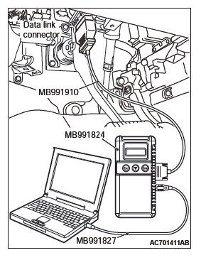
STEP 1. Using scan tool MB991958, read the diagnostic trouble code.
CAUTION To prevent damage to scan tool MB991958, always turn the ignition switch to the "LOCK" (OFF) position before connecting or disconnecting scan tool MB991958.
- Connect scan tool MB991958. Refer to GROUP 42B, "How to connect scan tool (M.U.T.-III)".
- Turn the ignition switch to the "ON" position.
- Check whether the ETACS-ECU related DTC is set.
- Turn the ignition switch to the "LOCK" (OFF) position.
Q: Is the DTC set?
YES : Diagnose the ETACS-ECU.
NO : Go to Step 2.
STEP 2. Check sunroof switch connector D-03 for loose, corroded or damaged terminals, or terminals pushed back in the connector.
Q: Is sunroof switch connector D-03 in good condition?
YES : Go to Step 3.
NO : Repair or replace the damaged component(s). Refer to GROUP 00E, Harness Connector Inspection. Check that the sunroof works normally.
STEP 3. Sunroof switch check
- Remove the sunroof switch.
- Check continuity when the sunroof switch is operated to "TILT-UP" position.
Q: Is the sunroof switch normal?
YES : Go to Step 4.
NO : Replace the sunroof switch. Check that the sunroof works normally.
STEP 4. Check sunroof motor assembly connector D-04 for loose, corroded or damaged terminals, or terminals pushed back in the connector.
Q: Is sunroof motor assembly connector D-04 in good condition?
YES : Go to Step 5.
NO : Repair or replace the damaged component(s). Refer to GROUP 00E, Harness Connector Inspection. Check that the sunroof works normally.
STEP 5. Check the wiring harness between sunroof switch connector D-03 (terminal 3) and sunroof motor assembly connector D-04 (terminal 4).
- Check the power supply line for open circuit and short circuit.
Q: Is the wiring harness between sunroof switch connector D-03 (terminal 3) and sunroof motor assembly connector D-04 (terminal No. 4) in good condition?
YES : Go to Step 6.
NO : The wiring harness may be damaged or the connector(s) may have loose, corroded or damaged terminals, or terminals pushed back in the connector.
Repair the wiring harness as necessary. Check that the sunroof works normally.
STEP 6. Retest the system.
Check that the sunroof lid glass tilts up normally.
Q: Is the check result normal?
YES : No action is necessary and testing is complete.
NO : Replace the sunroof motor assembly. Check that the sunroof works normally.
INSPECTION PROCEDURE 3: The Sunroof Lid Glass does not Open (Tilt-up, Tilt-down and Close Normally).
CAUTION Before replacing the ECU, ensure that the power supply circuit, the ground circuit and the communication circuit are normal.
Sunroof Switch Circuit
TECHNICAL DESCRIPTION (COMMENT)
The sunroof switch or the sunroof motor assembly may be defective.
TROUBLESHOOTING HINTS
- The sunroof switch may be defective
- The sunroof motor assembly may be defective
- The wiring harness or connectors may have loose, corroded, or damaged terminals, or terminals pushed back in the connector
DIAGNOSTIC PROCEDURE
Required Special Tools:
- MB992006: Extra fine probe
- MB991223: Harness set
- MB991958: Scan Tool (M.U.T.-III Sub Assembly)
- MB991824: Vehicles Communication Interface (V.C.I.)
- MB991827: M.U.T.-III USB Cable
- MB991910: M.U.T.-III Main Harness A (Vehicles with CAN communication system)
STEP 1. Using scan tool MB991958, read the diagnostic trouble code.
CAUTION To prevent damage to scan tool MB991958, always turn the ignition switch to the "LOCK" (OFF) position before connecting or disconnecting scan tool MB991958.
- Connect scan tool MB991958. Refer to GROUP 42B, "How to connect scan tool (M.U.T.-III)".
- Turn the ignition switch to the "ON" position.
- Check whether the ETACS-ECU related DTC is set.
- Turn the ignition switch to the "LOCK" (OFF) position.
Q: Is the DTC set?
YES : Diagnose the ETACS-ECU.
NO : Go to Step 2.
STEP 2. Check sunroof switch connector D-03 for loose, corroded or damaged terminals, or terminals pushed back in the connector.
Q: Is sunroof switch connector D-03 in good condition?
YES : Go to Step 3.
NO : Repair or replace the damaged component(s). Refer to GROUP 00E, Harness Connector Inspection. Check that the sunroof works normally.
STEP 3. Sunroof switch check
- Remove the sunroof switch.
- Check continuity when the sunroof switch is operated to "OPEN" position.
Q: Is the sunroof switch normal?
YES : Go to Step 4.
NO : Replace the sunroof switch.
STEP 4. Check sunroof motor assembly connector D-04 for loose, corroded or damaged terminals, or terminals pushed back in the connector.
Q: Is sunroof motor assembly connector D-04 in good condition?
YES : Go to Step 5.
NO : Repair or replace the damaged component(s). Refer to GROUP 00E, Harness Connector Inspection. Check that the sunroof works normally.
STEP 5. Check the wiring harness between sunroof switch connector D-03 (terminal 5) and sunroof motor assembly connector D-04 (terminal 5).
- Check the power supply line for open circuit and short circuit.
Q: Is the wiring harness between sunroof switch connector D-03 (terminal 5) and sunroof motor assembly connector D-04 (terminal No. 5) in good condition?
YES : Go to Step 6.
NO : The wiring harness may be damaged or the connector(s) may have loose, corroded or damaged terminals, or terminals pushed back in the connector.
Repair the wiring harness as necessary. Check that the sunroof works normally.
STEP 6. Retest the system.
Check that the sunroof lid glass opens normally.
Q: Is the check result normal?
YES : No action is necessary and testing is complete.
NO : Replace the sunroof motor assembly. Check that the sunroof works normally.
INSPECTION PROCEDURE 4: The Sunroof Lid Glass does not Tilt-down or Close (Tilt-up and Open Normally).
CAUTION Before replacing the ECU, ensure that the power supply circuit, the ground circuit and the communication circuit are normal.
Sunroof Switch Circuit
TECHNICAL DESCRIPTION (COMMENT)
The sunroof switch or the sunroof motor assembly may be defective.
TROUBLESHOOTING HINTS
- The sunroof switch may be defective
- The sunroof motor assembly may be defective
- The wiring harness or connectors may have loose, corroded, or damaged terminals, or terminals pushed back in the connector
DIAGNOSTIC PROCEDURE
Required Special Tools:
- MB992006: Extra fine probe
- MB991223: Harness set
- MB991958: Scan Tool (M.U.T.-III Sub Assembly)
- MB991824: Vehicles Communication Interface (V.C.I.)
- MB991827: M.U.T.-III USB Cable
- MB991910: M.U.T.-III Main Harness A (Vehicles with CAN communication system)
STEP 1. Using scan tool MB991958, read the diagnostic trouble code.
CAUTION To prevent damage to scan tool MB991958, always turn the ignition switch to the "LOCK" (OFF) position before connecting or disconnecting scan tool MB991958.
- Connect scan tool MB991958. Refer to GROUP 42B, "How to connect scan tool (M.U.T.-III)".
- Turn the ignition switch to the "ON" position.
- Check whether the ETACS-ECU related DTC is set.
- Turn the ignition switch to the "LOCK" (OFF) position.
Q: Is the DTC set?
YES : Diagnose the ETACS-ECU.
NO : Go to Step 2.
STEP 2. Check sunroof switch connector D-03 for loose, corroded or damaged terminals, or terminals pushed back in the connector.
Q: Is sunroof switch connector D-03 in good condition?
YES : Go to Step 3.
NO : Repair or replace the damaged component(s). Refer to GROUP 00E, Harness Connector Inspection. Check that the sunroof works normally.
STEP 3. Sunroof switch check
- Remove the sunroof switch.
- Check continuity when the sunroof switch is operated to "CLOSE/TILT-DOWN" position.
Q: Is the sunroof switch normal?
YES : Go to Step 4.
NO : Replace the sunroof switch.
STEP 4. Check sunroof motor assembly connector D-04 for loose, corroded or damaged terminals, or terminals pushed back in the connector.
Q: Is sunroof motor assembly connector D-04 in good condition?
YES : Go to Step 5.
NO : Repair or replace the damaged component(s). Refer to GROUP 00E, Harness Connector Inspection. Check that the sunroof works normally.
STEP 5. Check the wiring harness between sunroof switch connector D-03 (terminal 6) and sunroof motor assembly connector D-04 (terminal 10).
- Check the power supply line for open circuit and short circuit.
Q: Is the wiring harness between sunroof switch connector D-03 (terminal 6) and sunroof motor assembly connector D-04 (terminal No. 10) in good condition?
YES : Go to Step 6.
NO : The wiring harness may be damaged or the connector(s) may have loose, corroded or damaged terminals, or terminals pushed back in the connector.
Repair the wiring harness as necessary. Check that the sunroof works normally.
STEP 6. Retest the system.
Check that the sunroof lid glass tilts down or closes normally.
Q: Is the check result normal?
YES : No action is necessary and testing is complete.
NO : Replace the sunroof motor assembly. Check that the sunroof works normally.
INSPECTION PROCEDURE 5: Sunroof Safety Function does not Work Normally.
CAUTION Before replacing the ECU, ensure that the power supply circuit, the ground circuit and the communication circuit are normal.
CIRCUIT OPERATION
Malfunction of the sunroof motor assembly or incorrect learning of the sunroof fully closed position is suspected.
TROUBLESHOOTING HINTS
- Malfunction of the sunroof motor assembly
- Incorrect learning of the sunroof fully closed position
DIAGNOSTIC PROCEDURE
Required Special Tools:
- MB992006: Extra fine probe
- MB991223: Harness set
- MB991958: Scan Tool (M.U.T.-III Sub Assembly)
- MB991824: Vehicles Communication Interface (V.C.I.)
- MB991827: M.U.T.-III USB Cable
- MB991910: M.U.T.-III Main Harness A (Vehicles with CAN communication system)
STEP 1. Using scan tool MB991958, read the diagnostic trouble code.
CAUTION To prevent damage to scan tool MB991958, always turn the ignition switch to the "LOCK" (OFF) position before connecting or disconnecting scan tool MB991958.
- Connect scan tool MB991958. Refer to GROUP 42B, "How to connect scan tool (M.U.T.-III)".
- Turn the ignition switch to the "ON" position.
- Check whether the ETACS-ECU related DTC is set.
- Turn the ignition switch to the "LOCK" (OFF) position.
Q: Is the DTC set?
YES : Diagnose the sunroof motor assembly.
NO : Go to Step 2.
STEP 2. Check the trouble symptom.
Check the sunroof trouble symptom according to the following procedures.
- Carry out the learning procedures of the sunroof fully closed position.
- Check the trouble symptom.
Q: Is the check result normal?
YES : No action is necessary and testing is complete.
NO : Replace the sunroof motor assembly. Check that the sunroof works normally.
INSPECTION PROCEDURE 6: Sunroof Timer Lock Function does not Work Normally.
CAUTION Before replacing the ECU, ensure that the power supply circuit, the ground circuit and the communication circuit are normal.
CIRCUIT OPERATION
- The sunroof timer function works according to the
signals from the following switches:
- Ignition switch (IG1): OFF
- Front door switch (LH): OFF
- Front door switch (RH): OFF
- Vehicle condition
- Ignition switch: LOCK (OFF) position
- Front door (LH): Closed
- Front door (RH): Closed
- When the driver's door or the passenger's door are opened and closed while the sunroof timer function is on, the sunroof operative duration will be changed.
TECHNICAL DESCRIPTION (COMMENT)
If the sunroof timer function does not work normally, the input circuits from the switches described in "CIRCUIT OPERATION", the sunroof motor assembly, the ETACS-ECU or the LIN communication line may be defective.
TROUBLESHOOTING HINTS
- The front door switch may be defective
- The sunroof motor assembly may be defective
- The wiring harness or connectors may have loose, corroded, or damaged terminals, or terminals pushed back in the connector
PROBABLE CAUSES
- Malfunction of the driver's door switch
- Malfunction of the sunroof motor assembly
- Malfunction of ETACS-ECU
- Damaged wiring harness and connectors
DIAGNOSTIC PROCEDURE
Required Special Tools:
- MB992006: Extra fine probe
- MB991223: Harness set
- MB991958: Scan Tool (M.U.T.-III Sub Assembly)
- MB991824: Vehicles Communication Interface (V.C.I.)
- MB991827: M.U.T.-III USB Cable
- MB991910: M.U.T.-III Main Harness A (Vehicles with CAN communication system)
STEP 1. Check the power supply system.
With the ignition switch in the LOCK (OFF) position, check if the following function operates normally:
- Hazard warning light
- Central door locking system
Q: Is the check result normal?
YES : Go to Step 2.
NO : Refer to GROUP 54A, Malfunction of ETACS-ECU power supply circuit?
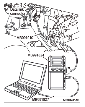
STEP 2. Using scan tool MB991958, read the diagnostic trouble code.
CAUTION To prevent damage to scan tool MB991958, always turn the ignition switch to the "LOCK" (OFF) position before connecting or disconnecting scan tool MB991958.
- Connect scan tool MB991958. Refer to GROUP 42B, "How to connect scan tool (M.U.T.-III)".
- Turn the ignition switch to the "ON" position.
- Check whether the ETACS-ECU related DTC is set.
- Turn the ignition switch to the "LOCK" (OFF) position.
Q: Is the DTC set?
YES : Diagnose the ETACS-ECU. Refer to GROUP 54A, Diagnosis?
NO : Go to Step 3.
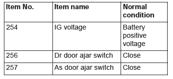
STEP 3. Using scan tool MB991958, check data list.
Check the signals related to the sunroof timer function operation.
CAUTION To prevent damage to scan tool MB991958, always turn the ignition switch to the "LOCK" (OFF) position before connecting or disconnecting scan tool MB991958.
- Connect scan tool MB991958. Refer to GROUP 42B, "How to connect scan tool (M.U.T.-III)".
- Turn the ignition switch to the "ON" position.
- Check the data list of the ETACS.
- Turn the ignition switch to the LOCK (OFF) position.
- Close the driver's door.
- Close the passenger's door.
- Turn the ignition switch to the "LOCK" (OFF) position.
OK: Normal condition is displayed.
Q: Is the check result normal?
Normal conditions are displayed for all the items. : Go to Step 4.
Normal condition is not displayed for item No. 254. : Refer to GROUP 54A, Inspection Procedure 2: ETACS-ECU does not receive any signal from the ignition switch (IG1).
Normal condition is not displayed for item No. 256. : Refer to GROUP 54A Inspection Procedure 5: ETACS-ECU does not receive any signal from the front door switch (LH).
Normal condition is not displayed for item No. 257. : Refer to GROUP 54A, Inspection Procedure 6: ETACS-ECU does not receive any signal from the front door switch (RH).
STEP 4. Retest the system.
Check that the sunroof timer function works normally.
Q: Is the check result normal?
YES : No action is necessary and testing is complete.
NO : Replace the ETACS-ECU. Check that the sunroof timer function works normally.
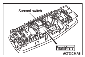
SUNROOF MOTOR ASSEMBLY TERMINAL CHECK
SPECIAL TOOLS
ON-VEHICLE SERVICE
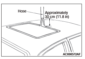
WATER TEST
Check if there are any leaks in the sunroof by the following procedure.
1. Fully close the sunroof lid glass.
2. Adjust the water pressure so that water comes out of the hose to a height of approximately 50 cm (19.7 inches) when the hose is held vertically facing upwards.
3. Hold the end of the hose approximately 30 cm (11.8 inches) above the roof and let the water run onto the weatherstrip for 5 minutes or more.
4. Check if any water leaks can be found in the room while watering. Even though there are any water leaks around the sunroof lid glass, it can be acceptable as long as water is caught in the drip area.
SUNROOF FIT ADJUSTMENT
1. Fully close the sunroof lid glass.
2. Fully open the sunshade.
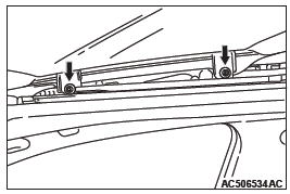
3. Loosen the sunroof lid glass assembly mounting screws.
Adjust the sunroof lid glass height by moving the sunroof lid glass assembly along the sunroof lid guide oblong hole so that the clearance between the sunroof lid glass and the vehicle body is even throughout the circumference.
4. After adjustment, check that the sunroof operates smoothly.
SUNROOF SAFETY FUNCTION CHECK
1. Close the sunroof lid glass while placing an approximately 10 mm thick piece of wood at right angles with the sunroof lid glass.
2. Check to see if the sunroof motor assembly turns in the opposite direction and the sunroof lid glass opens when the sunroof lid glass touches the wood. If any problem occurs, perform troubleshooting.
SUNROOF CHECK
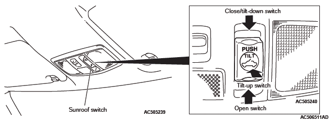
Check to see that the sunroof operates by pressing the sunroof switch. If it does not operate, perform troubleshooting.
SUNROOF TIMER FUNCTION CHECK
Check the system as described below. If the system does not work, carry out troubleshooting.
- Close the door and turn the ignition switch to the LOCK (OFF) position, and then check that the sunroof operates for 30 seconds.
- Close the door and turn the ignition switch to the LOCK (OFF) position. While the timer is on, open the driver's or front passenger's door, and check that the sunroof stays during the operation. (When the driver's or front passenger's door is opened while the timer is on, the timer will be turned off.)
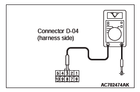
SUNROOF LID GLASS OPERATION CURRENT CHECK
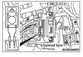
1. Remove the fuse of the sunroof to check that it is normal, then connect the circuit tester as shown in the Figure.
2. Turn ON the sunroof switch, then measure the operating current when the sunroof lid glass is halfway opened.
Standard value: 7 A or less [at 20 ºC (68 ºF) ]
3. Check the following areas if the operating current exceeds the standard value:
- Sunroof installation, deformation and presence of any foreign substances.
- Drive cable installation.
- Tilting of sunroof lid glass.
LEARNING PROCEDURES OF THE SUNROOF FULLY CLOSED POSITION
SHIFTING CONDITIONS FOR THE FULLY CLOSED POSITION ADJUSTMENT MODE
- When shifting to the forced fully closed position adjustment mode How to shift to the forced fully closed position adjustment mode
- Turn the ignition switch to the "ON" position.
- With the sunroof lid glass stopped (the position of the sunroof lid glass can be any position between fully opened and fully closed), press and hold the up switch for 10 seconds.
- When the anti-trap function (safety mechanism) is activated consecutively five times
- When the position information may be incorrect due to abnormal power supply during the sunroof operation
NOTE: When installing the sunroof assembly, or installing/ replacing the sunroof motor assembly, operate the forced fully closed position adjustment mode to adjust the fully closed position.
HOW TO ADJUST THE FULLY CLOSED POSITION FORCED FULLY CLOSED POSITION ADJUSTMENT MODE
1. With the sunroof lid glass stopped (the position of the sunroof lid glass can be any position between fully opened and fully closed), press and hold the up switch.
NOTE: If operating the up switch moves the sunroof normally, use the open switch to fully open the sunroof lid glass.
After the sunroof lid glass stops, press and hold the up switch.
2. Use the up switch to set the sunroof lid glass to the tilt-up position. The sunroof lid glass activates for approximately 30 mm and stops automatically when the switch is pressed once. Repeat this operation until the tilt-up position is reached and hold there for 3 seconds so that the fully closed position learning is completed.
HOW TO ADJUST THE FULLY CLOSED POSITION SUCH AS WHEN THE SAFETY FUNCTION IS ACTIVATED CONSECUTIVELY FIVE TIMES
Use the up switch to set the sunroof lid glass to the tilt-up position.
The sunroof lid glass activates for approximately 30 mm and stops automatically when the switch is pressed once.
Repeat this operation until the tilt-up position is reached and hold there for 3 seconds so that the fully closed position learning is completed.
SUNROOF OPERATION CHECK
CAUTION Check that the following items are normal before carrying out this operation check:
- Installation condition of the sunroof assembly
- Installation condition, deformation and contamination of the sunroof drive cable
- Installation condition of sunroof lid glass
- Sunroof switch and sunroof motor assembly
Check that the following items. If faulty, replace the sunroof motor assembly.
BASIC OPERATION
SUNROOF TIMER MECHANISM
In cases except the following, the basic operation and jam preventing mechanism will be maintained for thirty seconds after the ignition switch is turned to the "LOCK" (OFF) position (Sunroof timer function).
- If you open a door within that period (i.e. a door switch is on), the sunroof timer function will be cancelled immediately.
SAFETY MECHANISM
- If any obstacle such as a hand or a head is
detected to be pinched during a sunroof lid glass
closing operation, the sunroof lid glass is opened
by approximately 200 mm (7.9 inches) or more.
(Safety mechanism)
- During the sunroof lid glass closing operation, by continuing the sunroof close switch operation, the sunroof can be forcibly closed without activating the safety mechanism even when an obstacle is detected to be pinched.
- During the safety mechanism activation, when the sunroof close switch is operated, the sunroof lid glass stops. By continuing the close switch operation, the sunroof lid glass can be forcibly closed without activating the safety mechanism even when an obstacle is detected to be pinched.
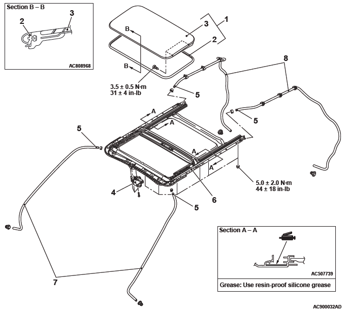
SUNROOF
REMOVAL AND INSTALLATION
Post-installation operation
Roof lid glass assembly and sunroof assembly
- Sunroof leakage check
- Sunroof alignment
- Learning procedures for sunroof fully closed position
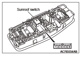
Sunroof switch removal
- Front dome light assembly
Sunroof lid glass assembly removal
- Sunroof lid glass assembly
- Sunroof lid weatherstrip
- Sunroof lid glass
Sunroof motor assembly removal steps
- Front dome light bracket
- Sunroof motor assembly
Sunroof assembly removal steps
- Front energy absorber roof bracket vehicles with curtain air bag
- Rear monitor bracket <Vehicles with rear monitor>
- Drain pipe connection
- Sunroof assembly
Drain pipe removal steps
- Headlining
- Splash shield front
- Front drain pipe
- Splash shield rear (rear bumper side)
- Rear drain pipe
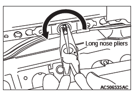
REMOVAL SERVICE POINT
SUNROOF ASSEMBLY REMOVAL
Use a pair of long nose pliers or the like to remove the sunroof assembly while turning it in the direction shown in the figure.
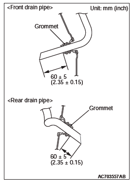
INSTALLATION SERVICE POINT
FRONT DRAIN PIPE/REAR DRAIN PIPE INSTALLATION
Install the grommet, and adjust the drain pipe projection as shown.
INSPECTION
SUNROOF SWITCH CONTINUITY CHECK
DISASSEMBLY AND ASSEMBLY
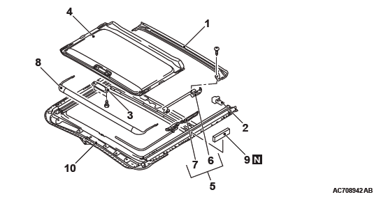
Disassembly steps
- Sunroof drip rail
- Sunroof sunshade stopper
- Sunroof sunshade knob
- Sunroof sunshade
- Sunroof drip plate and sunroof lid slide guide
- Sunroof drip plate
- Sunroof lid slide guide
- Sunroof deflector
- Sunroof pad
- Sunroof housing
REMOVAL SERVICE POINTS
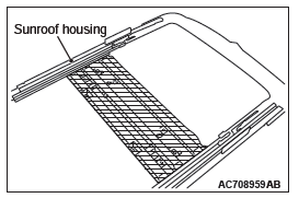
SUNROOF SUNSHADE REMOVAL
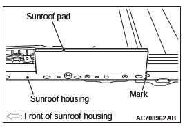
CAUTION Before removing the sunroof sunshade, clean the shaded area of the sunroof housing shown in the illustration. Otherwise, the sunroof sunshade may get dirty when it is removed.
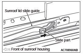
SUNROOF DRIP PLATE AND SUNROOF LID SLIDE GUIDE REMOVAL
Slide the slide part of the sunroof lid slide guide to the rear of the sunroof housing, and then pull out the sunroof drip plate and sunroof lid slide guide.
INSTALLATION SERVICE POINTS
SUNROOF PAD INSTALLATION
Align the sunroof pad with the mark on the sunroof housing, and then install it.
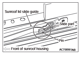
SUNROOF DRIP PLATE AND SUNROOF LID SLIDE GUIDE INSTALLATION
1. Install the sunroof drip plate and sunroof lid slide guide to the sunroof housing.
2. Push the sunroof drip plate and sunroof lid slide guide toward the front of sunroof housing until they stop.
CAUTION If the slide part of the sunroof lid slide guide is positioned incorrectly, the sunroof may not work normally.
3. Push the slide part of the sunroof lid slide guide forward.
Align the pin center of the slide part with the location shown in the illustration.
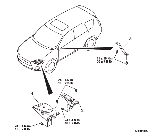
Loose Panel
REMOVAL AND INSTALLATION
<Headlight support upper panel>
Headlight support upper panel removal steps
- Headlight support panel cover
- Front bumper
- Headlight
- Headlight support upper panel cover
- Hood lock release cable
- Hood latch
- Air cleaner intake duct
- Front impact sensor
- Front harness
- Headlight support upper panel
INSTALLATION SERVICE POINT
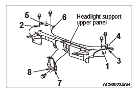
HEADLIGHT SUPPORT UPPER PANEL INSTALLATION
Install the mounting bolts of headlight support upper panel in the order shown in the illustration.
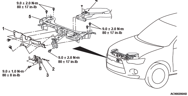
Battery bracket removal steps <3000>
- Battery tray
- Battery bracket (Front side)
- Battery bracket (Rear side)
Front floor backbone brace removal
- Front floor backbone brace <2WD>
READ NEXT:
 General Information
NOTE: In this manual, F.A.S.T.-key (Free-hand
Advanced Security Transmitter) is described as Keyless
Operation System (KOS).
The keyless operation system (KOS) enables the
driver to unlock all the doo
Diagnosis
STANDARD FLOW OF DIAGNOSTIC
TROUBLESHOOTING
Refer to GROUP 00 − How to Use Troubleshooting/Inspection
Service Points.
DIAGNOSTIC FUNCTION
HOW TO CONNECT THE SCAN TOOL (M.U.T.-III)
Required Spec
SEE MORE:
DTC P0010, P0011, P0013, P0014, P0016, P0017, P0031, P0032, P0037, P0038
DTC P0010: Intake Engine Oil Control Valve Circuit
CIRCUIT OPERATION
The intake engine oil control valve power is supplied
from the MFI relay (terminal No. 2).
The ECM controls ground intake engine oil control
valve by turning the power transistor in the
ECM "ON" and "OFF".
TECHNICAL DESCR
Bonnet
To open
1. Pull the release lever toward you to unlock the bonnet.
2. Raise the bonnet while pressing the safety lock.
NOTE:
● Only open the bonnet when the wipers are in the parked position. In any other
position, the wipers could damage the paint or bonnet.
3. Support the bonnet
