Mitsubishi Outlander: General Information
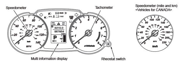
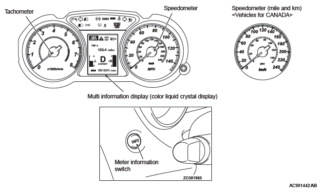
CONSTRUCTION DIAGRAM
<Except color liquid crystal display>
<Color liquid crystal display>
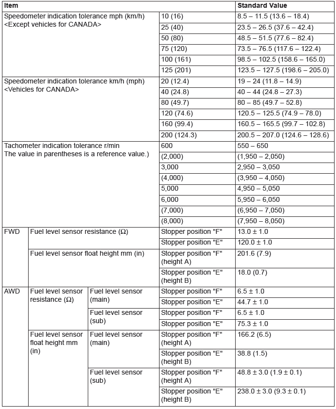
SERVICE SPECIFICATIONS
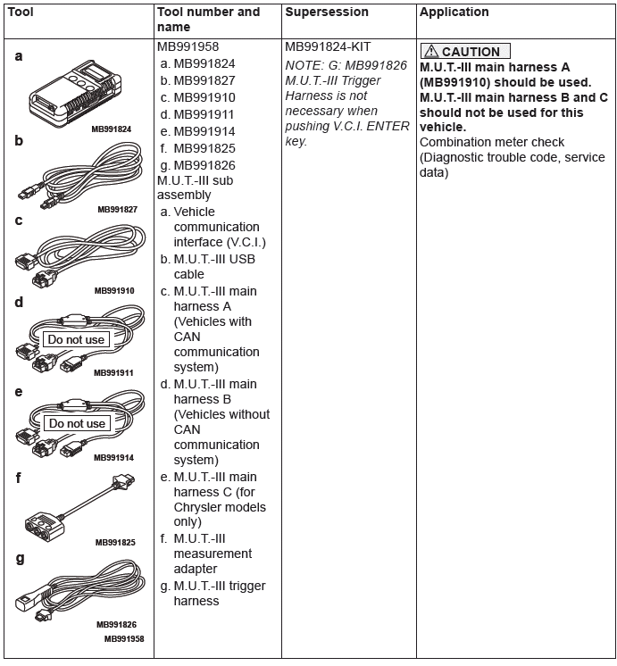
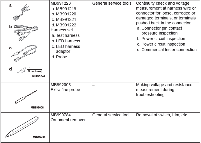
SPECIAL TOOLS
COMBINATION METERS DIAGNOSTIC
STANDARD FLOW OF DIAGNOSTIC TROUBLESHOOTING
Refer to GROUP 00, Contents of troubleshooting.
DIAGNOSTIC FUNCTION
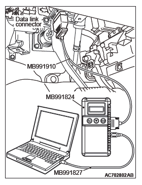
HOW TO CONNECT THE SCAN TOOL (M.U.T.-III)
Required Special Tools:
- MB991958: Scan Tool (M.U.T.-III Sub Assembly)
- MB991824: Vehicles Communication Interface (V.C.I.)
- MB991827: M.U.T.-III USB Cable
- MB991910: M.U.T.-III Main Harness A (Vehicles with CAN communication system)
CAUTION To prevent damage to scan tool MB991958, always turn the ignition switch to the "LOCK" (OFF) position before connecting or disconnecting scan tool MB991958.
1. Ensure that the ignition switch is at the "LOCK" (OFF) position.
2. Start up the personal computer.
3. Connect special tool MB991827 to special tool MB991824 and the personal computer.
4. Connect special tool MB991910 to special tool MB991824.
5. Connect special tool MB991910 to the data link connector.
6. Turn the power switch of special tool MB991824 to the "ON" position.
NOTE: When special tool MB991824 is energized, special tool MB991824 indicator light will be illuminated in a green color. 7. Start the M.U.T.-III system on the personal computer.
NOTE: Disconnecting scan tool MB991958 is the reverse of the connecting sequence, making sure that the ignition switch is at the "LOCK" (OFF) position.
HOW TO READ AND ERASE DIAGNOSTIC TROUBLE CODES
Required Special Tools:
- MB991958: Scan Tool (M.U.T.-III Sub Assembly)
- MB991824: Vehicles Communication Interface (V.C.I.)
- MB991827: M.U.T.-III USB Cable
- MB991910: M.U.T.-III Main Harness A (Vehicles with CAN communication system)
NOTE: If the battery voltage is low, diagnostic trouble codes will not be set. Check the battery if scan tool MB991958 does not display.
1. Connect scan tool MB991958 to the data link connector.
2. Turn the ignition switch to the "ON" position.
3. Select "System select" from the start-up screen.
4. Select "From 2006 MY" of "Model Year". When the "Vehicle Information" is displayed, check the contents.
5. Select "Meter" from "System List," and press the "OK" button.
NOTE: When the "Loading Option Setup" list is displayed, check the applicable item.
6. Select "Diagnostic Trouble Code" to read the DTC.
7. If a DTC is set, it is shown.
8. Choose "Erase DTCs" to erase the DTC.
HOW TO DIAGNOSE THE CAN BUS LINES
Required Special Tools:
- MB991958: Scan Tool (M.U.T.-III Sub Assembly)
- MB991824: Vehicles Communication Interface (V.C.I.)
- MB991827: M.U.T.-III USB Cable
- MB991910: M.U.T.-III Main Harness A (Vehicles with CAN communication system)
1. Connect scan tool MB991958 to the data link connector.
2. Turn the ignition switch to the "ON" position.
3. Select "CAN bus diagnosis" from the start-up screen.
4. When the vehicle information is displayed, confirm that it matches the vehicle being diagnosed.
- If they match, go to Step 8.
- If not, go to Step 5.
5. Select the "view vehicle information" button.
6. Enter the vehicle information and select the "OK" button.
7. When the vehicle information is displayed, confirm again that it matches the vehicle being diagnosed.
- If they match, go to Step 8.
- If not, go to Step 5.
8. Select the "OK" button.
9. When the optional equipment screen is displayed, choose the one which the vehicle is fitted with, and then select the "OK" button.
CHECK OF FREEZE FRAME DATA
The freeze frame data can be checked by using the scan tool (GROUP 00, How to Cope with Intermittent Malfunction).
When detecting fault and storing the DTC, the ECU connected to CAN bus line obtains the data before the determination of the DTC and the data when the DTC is determined, and then stores the ECU status of that time. By analyzing each data from scan tool, the troubleshooting can be performed more efficiently.
The displayed items are as the table below.
DISPLAY ITEM LIST
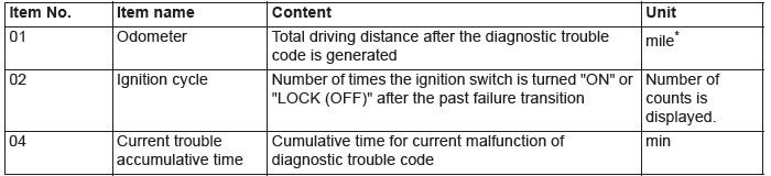
NOTE: *: If a failure occurs to both the ABS-ECU, ASC-ECU and ETACS-ECU, 0000 mile or FFFF mile is displayed on the scan tool MB991958.
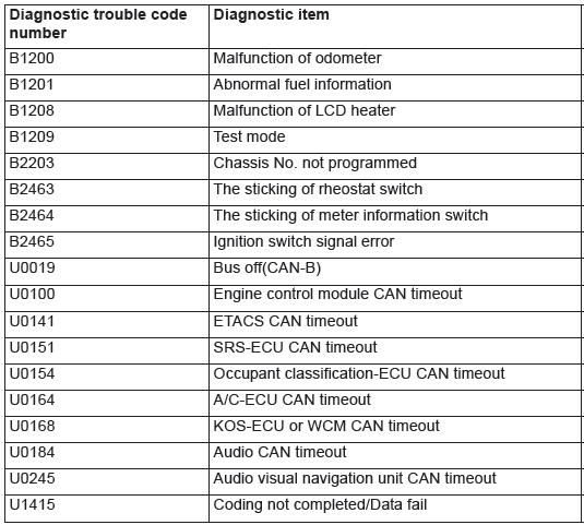
DIAGNOSTIC TROUBLE CODE CHART
CAUTION
- During troubleshooting, a DTC code associated with other system may be set when the ignition switch is turned on with connector(s) disconnected. On completion, check all systems for DTC code(s). If DTC code(s) are set, erase them all.
- When the combination meter is required to be replaced as a result of the troubleshooting, the current driving distance and number of elapsed days to be used for service reminder function must be entered into the meter after the replacement. Therefore, read "Integrated mileage for reminder," "Integrated days for reminder," "Mileage until Extra reminder," "Months until Extra reminder," and "Current Schedule" from the meter before the replacement using the special function of scan tool MB991958, and note them. For the operation method of scan tool MB991958. If "Integrated mileage for reminder" or "Integrated days for reminder" cannot be read by the scan tool MB991958, follow the method described below.
- For the driving distance for check warning, use the driving distance displayed on the multi information display.
- For the elapsed days for check warning, calculate the number of elapsed days from the delivery date to the customer (service remainder function start date) and current date.
READ NEXT:
 Diagnostic Trouble Code Procedures
DTC B1200: Malfunction of odometer
TROUBLE JUDGMENT
If the odometer information, which is stored in the
combination meter, is abnormal when the ignition
switch at the ON position and the system voltag
Symptom Procedures
Inspection Procedure 1: Power supply circuit check.
Combination Meter Power Supply Circuit
TECHNICAL DESCRIPTION (COMMENT)
If the odometer and trip meter are not displayed or all
the meter needles d
Check Procedure For Each Multi Information Display Screen
CHECK PROCEDURE FOR EACH MULTI INFORMATION DISPLAY SCREEN
<VEHICLES WITHOUT COLOR LIQUID CRYSTAL DISPLAY>
CAUTION
When there are TV towers, substations, or broadcasting
stations which emit stron
SEE MORE:
Power steering system
When the engine is stopped, the power steering system will not function and it
will require greater manual effort to operate the steering wheel. Keep this in mind
in particular when towing the vehicle. Never turn off the engine while driving.
Periodically check the power steering fluid level.
Manual A/C Diagnosis
INTRODUCTION TO HEATER, AIR CONDITIONING AND VENTILATION DIAGNOSIS
Air is drawn into the heater assembly from either the
outside, or from the inside of the passenger cabin if
DEFROST, maximum cooling or RECIRCULATION
are selected. The air is then forced through the evaporator
where heat is removed,
