Mitsubishi Outlander: Diagnostic Trouble Code Procedures
DTC B1200: Malfunction of odometer
TROUBLE JUDGMENT
If the odometer information, which is stored in the combination meter, is abnormal when the ignition switch at the ON position and the system voltage is 10 −16 volts (data from ETACS-ECU), DTC B1200 is stored.
TROUBLESHOOTING HINTS
The combination meter may be defective.
DIAGNOSIS
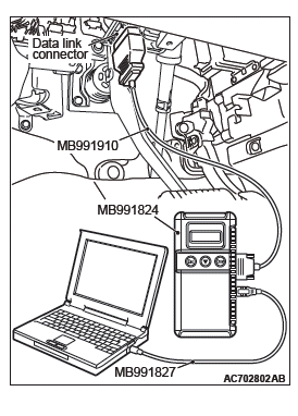
Required Special Tools:
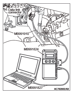
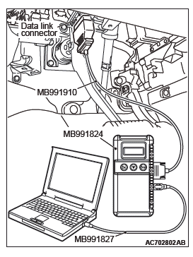
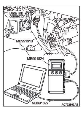
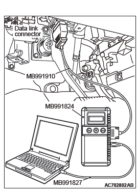
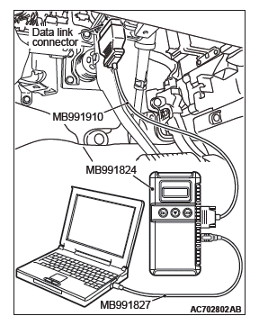
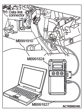
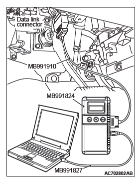
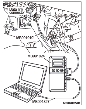
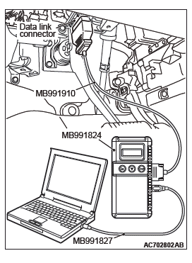
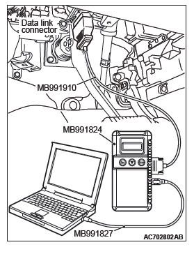
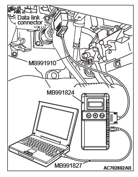
- MB991958: Scan Tool (M.U.T.-III Sub Assembly)
- MB991824: Vehicles Communication Interface (V.C.I.)
- MB991827: M.U.T.-III USB Cable
- MB991910: M.U.T.-III Main Harness A (Vehicles with CAN communication system)
STEP 1. Using scan tool MB991958, read the combination meter diagnostic trouble code.
Check if DTC is set to the combination meter.
CAUTION To prevent damage to scan tool MB991958, always turn the ignition switch to the "LOCK" (OFF) position before connecting or disconnecting scan tool MB991958.
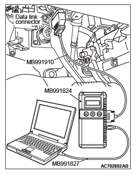
(1) Connect scan tool MB991958. Refer to "How to connect the Scan Tool (M.U.T.-III)".
(2) Turn the ignition switch to the "ON" position.
(3) Erase the DTC.
(4) Turn the ignition switch from "LOCK" (OFF) position to "ON" position.
(5) Check if diagnostic trouble code is set.
Q: Is the DTC set?
YES : Replace the combination meter, and then go to Step 2.
NO : The trouble can be an intermittent malfunction.
STEP 2. Recheck for diagnostic trouble code.
Check if DTC is set to the combination meter.
(1) Erase the DTC.
(2) Turn the ignition switch from "LOCK" (OFF) position to "ON" position.
(3) Check if diagnostic trouble code is set.
Q: Is the DTC set?
YES : Go to Step 1.
NO : The procedure is complete.
DTC B1201: Abnormal fuel information
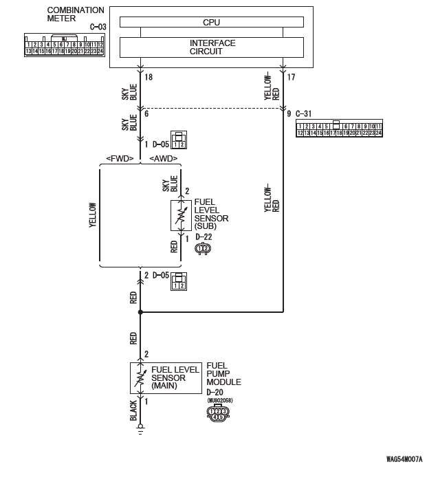
Fuel Gauge Unit Circuit
CAUTION Whenever the ECU is replaced, ensure that the communication circuit is normal.
TROUBLE JUDGMENT
With the ignition switch at the ON position and the system voltage at 10 −16 volts (data from ETACS-ECU), if the combination meter detects the abnormal resistance of fuel level sensor circuit for 64 seconds continuously, DTC B1201 is stored.
TROUBLESHOOTING HINTS
- The fuel pump module [fuel level sensor (main) ] may be defective. <FWD, AWD>
- The fuel level sensor (sub) may be defective.
<AWD>
- The combination meter may be defective.
- The wiring harness or connectors may have loose, corroded, or damaged terminals, or terminals pushed back in the connector
DIAGNOSIS
Required Special Tools:
- MB991223: Harness Set
- MB992006: Extra Fine Probe
- MB991958: Scan Tool (M.U.T.-III Sub Assembly)
- MB991824: Vehicles Communication Interface (V.C.I.)
- MB991827: M.U.T.-III USB Cable
- MB991910: M.U.T.-III Main Harness A (Vehicles with CAN communication system)
STEP 1. Check the malfunctioning vehicle.
Q: Is the malfunctioning vehicle a FWD?
YES <FWD> : Go to Step 2.
NO <AWD> : Go to Step 8.
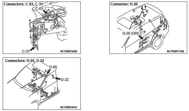
STEP 2. Check fuel pump module connector D-20 for loose, corroded or damaged terminals, or terminals pushed back in the connector.
Q: Is fuel pump module connector D-20 in good condition?
YES : Go to Step 3.
NO : Repair the connector.
STEP 3. Check the fuel level sensor (main).
Check to see if the fuel level sensor (main) is normal.
Q: Is the check result normal?
YES : Go to Step 4.
NO : Replace the fuel level sensor (main).
STEP 4. Measure the resistance at fuel pump module connector D-20.
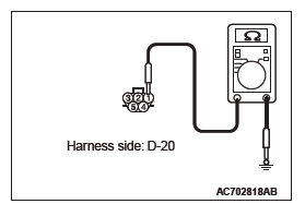
(1) Disconnect pump module connector D-20, and measure at the wiring harness side.
(2) Measure the resistance value between terminal 1 and ground.
- The measured value should be 2 ohm or less.
Q: Does the measured resistance value correspond with this range?
YES : Go to Step 6.
NO : Go to Step 5.
STEP 5. Check the wiring harness between fuel pump module connector D-20 (terminal 1) and ground.
- Check the ground wire for open circuit.
Q: Is the wiring harness between fuel pump module connector D-20 (terminal 1) and ground in good condition?
YES : There is no action to be taken.
NO : Repair the wiring harness.
STEP 6. Check combination meter connector C-03 for loose, corroded or damaged terminals, or terminals pushed back in the connector.
Q: Is combination meter connector C-03 in good condition?
YES : Go to Step 7.
NO : Repair the connector.
STEP 7. Check the wiring harness between fuel pump module connector D-20 (terminal 2) and combination meter connector C-03 (terminal 17 or 18).
Check the communication lines for open circuit and short circuit.
NOTE: Also check intermediate connectors C-31 and D-05. If intermediate connectors C-31 and D-05 are damaged, repair or replace the connector as described in GROUP 00E, Harness Connector Inspection.
Q: Are the wiring harness between fuel pump module connector D-20 (terminal 2) and combination meter connector C-03 (terminal 17 or 18) in good condition?
YES : Go to Step 14.
NO : Repair the wiring harness. The fuel gauge should work normally.
STEP 8. Check fuel pump module connector D-20 and fuel level sensor (sub) connector D-22 <AWD> for loose, corroded or damaged terminals, or terminals pushed back in the connector.
Q: Is fuel pump module connector D-20 and fuel level sensor (sub) connector D-22 <AWD> in good condition?
YES : Go to Step 9.
NO : Repair the connector.
STEP 9. Check the fuel level sensor (main) and (sub).
Check to see if the fuel level sensor (main) and (sub) is normal.
Q: Is the check result normal?
YES : Go to Step 10.
NO : Replace the fuel level sensor (main) or (sub).
STEP 10. Measure the resistance at fuel pump module connector D-20.
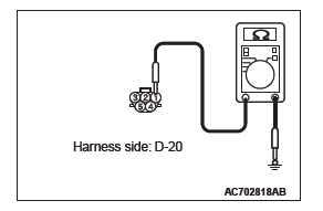
(1) Disconnect fuel pump module connector D-20, and measure at the wiring harness side.
(2) Measure the resistance value between terminal 1 and ground.
- The measured value should be 2 ohm or less.
Q: Does the measured resistance value correspond with this range?
YES : Go to Step 12.
NO : Go to Step 11.
STEP 11. Check the wiring harness between fuel pump module connector D-20 (terminal 1) and ground.
- Check the ground wire for open circuit.
Q: Is the wiring harness between fuel pump module connector D-20 (terminal 1) and ground in good condition?
YES : There is no action to be taken.
NO : Repair the wiring harness.
STEP 12. Check combination meter connector C-03 for loose, corroded or damaged terminals, or terminals pushed back in the connector.
Q: Is combination meter connector C-03 in good condition?
YES : Go to Step 13.
NO : Repair the connector.
STEP 13. Check the wiring harness between fuel pump module connector D-20 (terminal 2) and combination meter connector C-03 (terminal 17 or 18).
- Check the communication lines for open circuit and short circuit.
NOTE: Also check intermediate connectors C-31 and D-05. If intermediate connectors C-31 and D-05 are damaged, repair or replace the connector as described in GROUP 00E, Harness Connector Inspection.
Q: Are the wiring harness between fuel pump module connector D-20 (terminal 2) and combination meter connector C-03 (terminal 17 or 18) in good condition?
YES : Go to Step 14.
NO : Repair the wiring harness. The fuel gauge should work normally.
STEP 14. Using scan tool MB991958, perform actuator test.
Item 03: Fuel gauge (target value): 0 →100%
Fuel gauge shows 100 %
Q: Is the check result normal?
YES : Go to Step 15.
NO : Replace the combination meter.
STEP 15. Recheck for diagnostic trouble code.
Check again if the DTC is set to the combination meter.
(1) Erase the DTC.
(2) Turn the ignition switch from "LOCK" (OFF) position to "ON" position.
(3) Check if DTC is set.
Q: Is the DTC set?
YES : Replace the combination meter.
NO : The procedure is complete.
DTC B1208: Malfunction of LCD heater
TROUBLE JUDGMENT
With the ignition switch at the ON position and the system voltage at 10 −16 volts (data from ETACS-ECU), if the combination meter detects the LCD heater malfunction, the DTC B1208 is stored.
TROUBLESHOOTING HINTS
The combination meter may be defective
DIAGNOSIS
Required Special Tools:
- MB991958: Scan Tool (M.U.T.-III Sub Assembly)
- MB991824: Vehicles Communication Interface (V.C.I.)
- MB991827: M.U.T.-III USB Cable
- MB991910: M.U.T.-III Main Harness A (Vehicles with CAN communication system)
Recheck for diagnostic trouble code.
Check again if the DTC is set to the combination meter.
CAUTION To prevent damage to scan tool MB991958, always turn the ignition switch to the "LOCK" (OFF) position before connecting or disconnecting scan tool MB991958.

(1) Connect scan tool MB991958. Refer to "How to connect the Scan Tool (M.U.T.-III)".
(2) Turn the ignition switch from "LOCK" (OFF) position to "ON" position.
(3) Check if DTC is set.
(4) Turn the ignition switch to the "LOCK" (OFF) position.
Q: Is the DTC set?
YES : Replace the combination meter.
NO : The procedure is complete.
DTC B1209: Test mode
TROUBLE JUDGMENT
When the mode is changed to the meter test mode (supplier mode), the combination meter stores the DTC B1209.
TROUBLESHOOTING HINTS
The combination meter may be defective
DIAGNOSIS
Replace the combination meter.
DTC B2203: Chassis No. not programmed
TROUBLE JUDGMENT
With the ignition switch at the ON position, if the chassis number code is not written to the combination meter, DTC B2203 is stored.
TROUBLESHOOTING HINTS
- The CAN bus line may be defective.
- The ETACS-ECU may be defective.
- The combination meter may be defective.
DIAGNOSIS
Required Special Tools:
- MB991958: Scan Tool (M.U.T.-III Sub Assembly)
- MB991824: Vehicles Communication Interface (V.C.I.)
- MB991827: M.U.T.-III USB Cable
- MB991910: M.U.T.-III Main Harness A (Vehicles with CAN communication system)
STEP 1. Using scan tool MB991958, diagnose the CAN bus line.
CAUTION To prevent damage to scan tool MB991958, always turn the ignition switch to the "LOCK" (OFF) position before connecting or disconnecting scan tool MB991958.
(1) Connect scan tool MB991958. Refer to "How to connect the Scan Tool (M.U.T.-III)".
(2) Turn the ignition switch to the "ON" position.
(3) Diagnose the CAN bus line.
(4) Turn the ignition switch to the "LOCK" (OFF) position.
Q: Is the CAN bus line found to be normal?
YES : Go to Step 2.
NO : Repair the CAN bus line.
STEP 2. Using scan tool MB991958, read the ETACS-ECU diagnostic trouble code.
Check again if the DTC is set to the ETACS-ECU.
Q: Is the DTC set?
YES : Troubleshoot the ETACS-ECU. NO : Go to Step 3.
STEP 3. Recheck for diagnostic trouble code.
Check again if the DTC is set to the combination meter.
(1) Erase the DTC.
(2) Turn the ignition switch from "LOCK" (OFF) position to "ON" position.
(3) Check if DTC is set.
(4) Turn the ignition switch to the "LOCK" (OFF) position.
Q: Is the DTC set?
YES : Replace the combination meter.
NO : The trouble can be an intermittent malfunction.
DTC B2463: The sticking of rheostat switch
TROUBLE JUDGMENT
If the combination meter detects the rheostat switch pressed state for 60 seconds or more continuously, DTC B2463 is stored.
TROUBLESHOOTING HINTS
- The combination meter may be defective.
- The meter hood assembly (rheostat switch knob) may be defective.
DIAGNOSTIC PROCEDURE
Required Special Tools:
- MB991958: Scan Tool (M.U.T.-III Sub Assembly)
- MB991824: Vehicles Communication Interface (V.C.I.)
- MB991827: M.U.T.-III USB Cable
- MB991910: M.U.T.-III Main Harness A (Vehicles with CAN communication system)
STEP 1. Check the rheostat switch.
Check whether an abnormality is present to the combination meter and the rheostat switch knob attached to the meter hood assembly.
Q: Is the check result normal?
YES : Go to Step 2.
NO : Replace the combination meter or meter hood assembly.
STEP 2. Using scan tool MB991958, read the combination meter diagnostic trouble code.
Check if DTC is set to the combination meter.
CAUTION To prevent damage to scan tool MB991958, always turn the ignition switch to the "LOCK" (OFF) position before connecting or disconnecting scan tool MB991958.
(1) Connect scan tool MB991958. Refer to "How to connect the Scan Tool (M.U.T.-III)".
(2) Turn the ignition switch to the "ON" position.
(3) Erase the DTC.
(4) Turn the ignition switch from "LOCK" (OFF) position to "ON" position.
(5) Check if diagnostic trouble code is set.
Q: Is the DTC set?
YES : Replace the combination meter, and then go to Step 3.
NO : The procedure is complete.
STEP 3. Recheck for diagnostic trouble code.
Check if DTC is set to the combination meter.
(1) Erase the DTC.
(2) Turn the ignition switch from "LOCK" (OFF) position to "ON" position.
(3) Check if diagnostic trouble code is set.
Q: Is the DTC set?
YES : Go to Step 1.
NO : The procedure is complete.
DTC B2464: The sticking of meter information switch
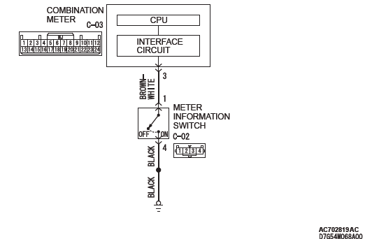
Meter Information Switch Circuit
CAUTION Whenever the ECU is replaced, ensure that the communication circuit is normal.
TROUBLE JUDGMENT
If the combination meter detects the meter information switch pressed state for 60 seconds or more continuously, DTC B2464 is stored.
TROUBLESHOOTING HINTS
- The meter information switch may be defective
- The combination meter may be defective
- The wiring harness or connectors may have loose, corroded, or damaged terminals, or terminals pushed back in the connector
DIAGNOSIS
Required Special Tools:
- MB991223: Harness Set
- MB992006: Extra Fine Probe
- MB991958: Scan Tool (M.U.T.-III Sub Assembly)
- MB991824: Vehicles Communication Interface (V.C.I.)
- MB991827: M.U.T.-III USB Cable
- MB991910: M.U.T.-III Main Harness A (Vehicles with CAN communication system)
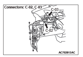
STEP 1. Check meter information switch connector C-02 for loose, corroded or damaged terminals, or terminals pushed back in the connector.
Q: Is meter information switch connector C-02 in good condition?
YES : Go to Step 2.
NO : Repair the connector.
STEP 2. Check the meter information switch.
Check the meter information switch.
Q: Is the check result normal?
YES : Go to Step 3.
NO : Replace the meter information switch.
STEP 3. Measure at meter information switch connector C-02 in order to the ground circuit to the meter information switch.
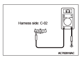
(1) Disconnect meter information switch connector C-02, and measure at the wiring harness side.
(2) Measure the resistance value between terminal 4 and ground.
- The measured value should be 2 ohm or less.
Q: Does the measured resistance value correspond with this range?
YES : Go to Step 5.
NO : Go to Step 4.
STEP 4. Check the wiring harness between meter information switch connector C-02 (terminal 4) and ground.
- Check the ground wire for open circuit.
Q: Is the wiring harness between fuel meter information switch connector C-02 (terminal 4) and ground in good condition?
YES : Go to Step 7.
NO : Repair the wiring harness, and then go to Step 7.
STEP 5. Check combination meter connector C-03 for loose, corroded or damaged terminals, or terminals pushed back in the connector.
Q: Is combination meter connector C-03 in good condition?
YES : Go to Step 6.
NO : Repair the connector, and then go to Step 7.
STEP 6. Check the wiring harness between meter information switch connector C-02 (terminal 1) and combination meter connector C-03 (terminal 3).
- Check the communication line for open circuit and short circuit.
Q: Are the wiring harness between meter information switch connector C-02 (terminal 1) and combination meter connector C-03 (terminal 3) in good condition?
YES : Go to Step 7.
NO : Repair the wiring harness, and then go to Step 7.
STEP 7. Recheck for diagnostic trouble code.
Check again if the DTC is set to the combination meter.
CAUTION To prevent damage to scan tool MB991958, always turn the ignition switch to the "LOCK" (OFF) position before connecting or disconnecting scan tool MB991958.
(1) Connect scan tool MB991958. Refer to "How to connect the Scan Tool (M.U.T.-III)".
(2) Turn the ignition switch to the "ON" position.
(3) Erase the DTC.
(4) Turn the ignition switch from "LOCK" (OFF) position to "ON" position.
(5) Check if DTC is set.
Q: Is the DTC set?
YES : Go to Step 1.
NO : The procedure is complete.
DTC B2465: Ignition switch signal error
TROUBLE JUDGMENT
If 5 seconds or more elapses with the ignition switch state and the data from the CAN communication contradicted, the combination meter stores the DTC B2465.
TROUBLESHOOTING HINTS
- The CAN bus line may be defective
- The ETACS-ECU may be defective
- The combination meter may be defective
DIAGNOSIS
Required Special Tools:
- MB991958: Scan Tool (M.U.T.-III Sub Assembly)
- MB991824: Vehicles Communication Interface (V.C.I.)
- MB991827: M.U.T.-III USB Cable
- MB991910: M.U.T.-III Main Harness A (Vehicles with CAN communication system)
STEP 1. Using scan tool MB991958, read the ETACS-ECU diagnostic trouble code
Check if DTC is set to the ETACS-ECU.
CAUTION To prevent damage to scan tool MB991958, always turn the ignition switch to the "LOCK" (OFF) position before connecting or disconnecting scan tool MB991958.
(1) Connect scan tool MB991958. Refer to "How to connect the Scan Tool (M.U.T.-III)".
(2) Turn the ignition switch from "LOCK" (OFF) position to "ON" position.
(3) Check if DTC is set.
(4) Turn the ignition switch to the "LOCK" (OFF) position.
Q: Is the DTC set?
YES : Troubleshoot the ETACS-ECU. NO : Go to Step 2.
STEP 2. Using scan tool MB991958, diagnose the CAN bus line.
(1) Turn the ignition switch to the "ON" position.
(2) Diagnose the CAN bus line.
(3) Turn the ignition switch to the "LOCK" (OFF) position.
Q: Is the CAN bus line found to be normal?
YES : Go to Step 3.
NO : Repair the CAN bus line.
STEP 3. Combination meter operation check Check that the combination meter works normally.
Q: Is the check result normal?
YES : Go to Step 4.
NO : Check the power supply circuit of combination meter.
STEP 4. Recheck for diagnostic trouble code.
Check again if the DTC is set to the combination meter.
(1) Erase the DTC.
(2) Turn the ignition switch from "LOCK" (OFF) position to "ON" position.
(3) Check if DTC is set.
(4) Turn the ignition switch to the "LOCK" (OFF) position.
Q: Is the DTC set?
YES : Replace the combination meter.
NO : The trouble can be an intermittent malfunction.
DTC U0019: Bus off (CAN-B)
CAUTION
- If DTC U0019 is set, be sure to diagnose the CAN bus line.
- When replacing the ECU, always check that the communication circuit is normal.
DIAGNOSTIC FUNCTION
- If the CAN-B circuit malfunction occurs, the combination meter sets DTC U0019.
JUDGMENT CRITERIA
With the ignition switch at the ON position and the system voltage at 10 − 16 volts (data from ETACS-ECU), if the combination meter becomes unable to transmit data normally due to the CAN-B bus circuit malfunction, the combination meter determines that a problem has occurred.
TROUBLESHOOTING HINTS
The CAN bus line may be defective
DIAGNOSIS
Required Special Tools:
- MB991958: Scan Tool (M.U.T.-III Sub Assembly)
- MB991824: Vehicles Communication Interface (V.C.I.)
- MB991827: M.U.T.-III USB Cable
- MB991910: M.U.T.-III Main Harness A (Vehicles with CAN communication system)
STEP 1.Recheck for diagnostic trouble code.
Check again if the DTC is set to the combination meter.
CAUTION To prevent damage to scan tool MB991958, always turn the ignition switch to the "LOCK" (OFF) position before connecting or disconnecting scan tool MB991958.
(1) Connect scan tool MB991958. Refer to "How to connect the Scan Tool (M.U.T.-III)".
(2) Turn the ignition switch from "LOCK" (OFF) position to "ON" position.
(3) Check if DTC is set.
(4) Turn the ignition switch to the "LOCK" (OFF) position.
Q: Is the DTC set?
YES : Go to Step 2.
NO : The trouble can be an intermittent malfunction.
STEP 2. Using scan tool MB991958, diagnose the CAN bus line.
(1) Turn the ignition switch to the "ON" position.
(2) Diagnose the CAN bus line.
(3) Turn the ignition switch to the "LOCK" (OFF) position.
Q: Is the CAN bus line found to be normal?
YES : The trouble can be an intermittent malfunction.
NO : Repair the CAN bus line.
DTC U0100: Engine control module CAN timeout
CAUTION
- If DTC U0100 is set, be sure to diagnose the CAN bus line.
- When replacing the ECU, always check that the communication circuit is normal.
DIAGNOSTIC FUNCTION
The combination meter sets DTC U0100 when it cannot receive "CHECK ENGINE" signals from the engine control module.
JUDGMENT CRITERIA
With the ignition switch in the ON position, system voltage between 10−16 volts (data from ETACS-ECU), power supply fuse (IOD fuse) is OK, or odometer value is 80.5 km (50 miles) or more, and the communication with engine control module cannot be established for 600 ms or more, the combination meter determines that a problem has occurred.
PROBABLE CAUSES
- The CAN bus line may be defective.
- The combination meter may be defective.
- The engine control module may be defective.
DIAGNOSIS
Required Special Tools:
- MB991958: Scan Tool (M.U.T.-III Sub Assembly)
- MB991824: Vehicles Communication Interface (V.C.I.)
- MB991827: M.U.T.-III USB Cable
- MB991910: M.U.T.-III Main Harness A (Vehicles with CAN communication system)
STEP 1. Using scan tool MB991958, diagnose the CAN bus line.
CAUTION To prevent damage to scan tool MB991958, always turn the ignition switch to the "LOCK" (OFF) position before connecting or disconnecting scan tool MB991958.
(1) Connect scan tool MB991958. Refer to "How to connect the Scan Tool (M.U.T.-III)".
(2) Turn the ignition switch to the "ON" position.
(3) Diagnose the CAN bus line.
(4) Turn the ignition switch to the "LOCK" (OFF) position.
Q: Is the CAN bus line found to be normal?
YES : Go to Step 2.
NO : Repair the CAN bus line.
STEP 2. Using scan tool MB991958, read the MFI diagnostic trouble code.
Check if DTC is set to the engine control module.
Q: Is the DTC set?
YES : Troubleshoot the MFI.
NO : Go to Step 3.
STEP 3. Using scan tool MB991958, read the ETACS diagnostic trouble code.
Check if DTC U0100 is set to the ETACS-ECU.
Q: Is the DTC set?
YES : Go to Step 4.
NO : Go to Step 5.
STEP 4. Recheck for diagnostic trouble code.
Check again if the DTC is set to the combination meter.
(1) Erase the DTC.
(2) Turn the ignition switch from "LOCK" (OFF) position to "ON" position.
(3) Check if DTC is set.
(4) Turn the ignition switch to the "LOCK" (OFF) position.
Q: Is the DTC set?
YES : Replace the engine control module.
NO : The trouble can be an intermittent malfunction such as a poor connection or open circuit in the CAN bus lines between the engine control module and the combination meter.
STEP 5. Recheck for diagnostic trouble code.
Check again if the DTC is set to the combination meter.
(1) Erase the DTC.
(2) Turn the ignition switch from "LOCK" (OFF) position to "ON" position.
(3) Check if DTC is set.
(4) Turn the ignition switch to the "LOCK" (OFF) position.
Q: Is the DTC set?
YES : Replace the combination meter.
NO : The trouble can be an intermittent malfunction such as a poor connection or open circuit in the CAN bus lines between the engine control module and the combination meter.
DTC U0141: ETACS CAN timeout
CAUTION
- If DTC U0141 is set, be sure to diagnose the CAN bus line.
- When replacing the ECU, always check that the communication circuit is normal.
DIAGNOSTIC FUNCTION
If the signal from ETACS-ECU cannot be received, the combination meter sets the DTC U0141.
JUDGMENT CRITERIA
With the ignition switch in the ON position, system voltage between 10 − 16 volts (data from ETACS-ECU), power supply fuse (IOD fuse) is OK, or odometer value is 80.5 km (50 miles) or more, and the communication with ETACS-ECU cannot be established for 2,500 ms or more, the combination meter determines that a problem has occurred.
TROUBLESHOOTING HINTS
- The CAN bus line may be defective
- The combination meter may be defective
- The ETACS-ECU may be defective
DIAGNOSIS
Required Special Tools:
- MB991958: Scan Tool (M.U.T.-III Sub Assembly)
- MB991824: Vehicles Communication Interface (V.C.I.)
- MB991827: M.U.T.-III USB Cable
- MB991910: M.U.T.-III Main Harness A (Vehicles with CAN communication system)
STEP 1. Using scan tool MB991958, diagnose the CAN bus line.
CAUTION To prevent damage to scan tool MB991958, always turn the ignition switch to the "LOCK" (OFF) position before connecting or disconnecting scan tool MB991958.
(1) Connect scan tool MB991958. Refer to "How to connect the Scan Tool (M.U.T.-III)".
(2) Turn the ignition switch to the "ON" position.
(3) Diagnose the CAN bus line.
(4) Turn the ignition switch to the "LOCK" (OFF) position.
Q: Is the CAN bus line found to be normal?
YES : Go to Step 2.
NO : Repair the CAN bus line.
STEP 2. Using scan tool MB991958, read the ETACS diagnostic trouble code.
Check if DTC is set to the ETACS-ECU.
Q: Is the DTC set?
YES : Diagnose the ETACS-ECU.
NO : Go to Step 3.
STEP 3. Using scan tool MB991958, read the A/C diagnostic trouble code.
Check if DTC U0141 is set to the A/C-ECU.
Q: Is the DTC set?
YES : Go to Step 4.
NO : Go to Step 5.
STEP 4. Recheck for diagnostic trouble code.
Check again if the DTC is set to the combination meter.
(1) Erase the DTC.
(2) Turn the ignition switch from "LOCK" (OFF) position to "ON" position.
(3) Check if DTC is set.
(4) Turn the ignition switch to the "LOCK" (OFF) position.
Q: Is the DTC set?
YES : Replace the ETACS-ECU.
NO : The trouble can be an intermittent malfunction such as a poor connection or open circuit in the CAN bus lines between the ETACS-ECU and the combination meter.
STEP 5. Recheck for diagnostic trouble code.
Check again if the DTC is set to the combination meter.
(1) Erase the DTC.
(2) Turn the ignition switch from "LOCK" (OFF) position to "ON" position.
(3) Check if DTC is set.
(4) Turn the ignition switch to the "LOCK" (OFF) position.
Q: Is the DTC set?
YES : Replace the combination meter.
NO : The trouble can be an intermittent malfunction such as a poor connection or open circuit in the CAN bus lines between the ETACS-ECU and the combination meter.
DTC U0151: SRS-ECU CAN timeout
CAUTION
- If DTC U0151 is set, be sure to diagnose the CAN bus line.
- When replacing the ECU, always check that the communication circuit is normal.
DIAGNOSTIC FUNCTION
If the signal from SRS-ECU cannot be received, the combination meter sets DTC U0151.
JUDGMENT CRITERIA
With the ignition switch in the ON position, system voltage between 10−16 volts (data from ETACS-ECU), power supply fuse (IOD fuse) is OK, or odometer value is 80.5 km (50 miles) or more, and the communication with SRS-ECU cannot be established for 2,500 ms or more, the combination meter determines that a problem has occurred.
TROUBLESHOOTING HINTS
- The CAN bus line may be defective
- The SRS-ECU may be defective
- The combination meter may be defective
DIAGNOSIS
Required Special Tools:
- MB991958: Scan Tool (M.U.T.-III Sub Assembly)
- MB991824: Vehicles Communication Interface (V.C.I.)
- MB991827: M.U.T.-III USB Cable
- MB991910: M.U.T.-III Main Harness A (Vehicles with CAN communication system)
STEP 1. Using scan tool MB991958, diagnose the CAN bus line.
CAUTION To prevent damage to scan tool MB991958, always turn the ignition switch to the "LOCK" (OFF) position before connecting or disconnecting scan tool MB991958.
(1) Connect scan tool MB991958. Refer to "How to connect the Scan Tool (M.U.T.-III)".
(2) Turn the ignition switch to the "ON" position.
(3) Diagnose the CAN bus line.
(4) Turn the ignition switch to the "LOCK" (OFF) position.
Q: Is the CAN bus line found to be normal?
YES : Go to Step 2.
NO : Repair the CAN bus line.
STEP 2. Using scan tool MB991958, read the SRS-ECU diagnostic trouble code.
Check again if the DTC is set to the SRS-ECU.
Q: Is the DTC set?
YES : Troubleshoot the SRS.
NO : Go to Step 3.
STEP 3. Using scan tool MB991958, read the A/C-ECU diagnostic trouble code.
Check if the DTC U0151 is set to the A/C-ECU.
Q: Is the DTC set?
YES : Go to Step 4.
NO : Go to Step 5.
STEP 4. Recheck for diagnostic trouble code.
Check again if the DTC is set to the combination meter.
(1) Erase the DTC.
(2) Turn the ignition switch from "LOCK" (OFF) position to "ON" position.
(3) Check if DTC is set.
(4) Turn the ignition switch to the "LOCK" (OFF) position.
Q: Is the DTC set?
YES : Replace the SRS-ECU.
NO : The trouble can be an intermittent malfunction such as a poor connection or open circuit in the CAN bus lines between the SRS-ECU and the combination meter.
STEP 5. Recheck for diagnostic trouble code.
Check again if the DTC is set to the combination meter.
(1) Erase the DTC.
(2) Turn the ignition switch from "LOCK" (OFF) position to "ON" position.
(3) Check if DTC is set.
(4) Turn the ignition switch to the "LOCK" (OFF) position.
Q: Is the DTC set?
YES : Replace the combination meter.
NO : The trouble can be an intermittent malfunction such as a poor connection or open circuit in the CAN bus lines between the SRS-ECU and the combination meter.
DTC U0154: Occupant classification-ECU CAN timeout
CAUTION
- If DTC U0154 is set, be sure to diagnose the CAN bus line.
- When replacing the ECU, always check that the communication circuit is normal.
DIAGNOSTIC FUNCTION
When the signals from occupant classification-ECU cannot be received, the combination meter sets DTC U0154.
JUDGMENT CRITERIA
With the ignition switch in the ON position, system voltage between 10 − 16 volts (data from ETACS-ECU), power supply fuse (IOD fuse) is OK, or odometer value is 80.5 km (50 miles) or more, and the communications with occupant classification- ECU cannot be established for 2,500 ms or more, the combination meter determines that a problem has occurred.
TROUBLESHOOTING HINTS
- The CAN bus line may be defective.
- The combination meter may be defective.
- The occupant classification-ECU may be defective.
DIAGNOSIS
Required Special Tools:
- MB991958: Scan Tool (M.U.T.-III Sub Assembly)
- MB991824: Vehicles Communication Interface (V.C.I.)
- MB991827: M.U.T.-III USB Cable
- MB991910: M.U.T.-III Main Harness A (Vehicles with CAN communication system)
STEP 1. Using scan tool MB991958, diagnose the CAN bus line.
CAUTION To prevent damage to scan tool MB991958, always turn the ignition switch to the "LOCK" (OFF) position before connecting or disconnecting scan tool MB991958.
(1) Connect scan tool MB991958. Refer to "How to connect the Scan Tool (M.U.T.-III)".
(2) Turn the ignition switch to the "ON" position.
(3) Diagnose the CAN bus line.
(4) Turn the ignition switch to the "LOCK" (OFF) position.
Q: Is the CAN bus line found to be normal?
YES : Go to Step 2.
NO : Repair the CAN bus line.
STEP 2. Using scan tool MB991958, read the SRS-ECU diagnostic trouble code.
Check if DTC is set to the SRS-ECU.
Q: Is the DTC set?
YES : Troubleshoot the SRS.
NO : Go to Step 3.
STEP 3. Using scan tool MB991958, read the A/C-ECU diagnostic trouble code.
Check if the DTC U0154 is set to the A/C-ECU.
Q: Is the DTC set?
YES : Go to Step 4.
NO : Go to Step 5.
STEP 4. Recheck for diagnostic trouble code.
Check again if the DTC is set to the combination meter.
(1) Erase the DTC.
(2) Turn the ignition switch from "LOCK" (OFF) position to "ON" position.
(3) Check if DTC is set.
(4) Turn the ignition switch to the "LOCK" (OFF) position.
Q: Is the DTC set?
YES : Replace the occupant classification-ECU.
NO : The trouble can be an intermittent malfunction such as a poor connection or open circuit in the CAN bus lines between the occupant classification-ECU and the combination meter.
STEP 5. Recheck for diagnostic trouble code.
Check again if the DTC is set to the combination meter.
(1) Erase the DTC.
(2) Turn the ignition switch from "LOCK" (OFF) position to "ON" position.
(3) Check if DTC is set.
(4) Turn the ignition switch to the "LOCK" (OFF) position.
Q: Is the DTC set?
YES : Replace the combination meter.
NO : The trouble can be an intermittent malfunction such as a poor connection or open circuit in the CAN bus lines between the occupant classification-ECU and the combination meter.
DTC U0164: A/C-ECU CAN timeout
CAUTION
- If DTC U0164 is set, be sure to diagnose the CAN bus line.
- When replacing the ECU, always check that the communication circuit is normal.
DIAGNOSTIC FUNCTION
If the signal from A/C-ECU cannot be received, the combination meter sets DTC U0164.
JUDGMENT CRITERIA
With the ignition switch in the ON position, system voltage between 10−16 volts (data from ETACS-ECU), power supply fuse (IOD fuse) is OK, or odometer value is 80.5 km (50 miles) or more, and the communication with A/C-ECU cannot be established for 2,500 ms or more, the combination meter determines that a problem has occurred.
TROUBLESHOOTING HINTS
- The CAN bus line may be defective.
- The A/C-ECU may be defective.
- The combination meter may be defective.
DIAGNOSIS
Required Special Tools:
- MB991958: Scan Tool (M.U.T.-III Sub Assembly)
- MB991824: Vehicles Communication Interface (V.C.I.)
- MB991827: M.U.T.-III USB Cable
- MB991910: M.U.T.-III Main Harness A (Vehicles with CAN communication system)
STEP 1. Using scan tool MB991958, diagnose the CAN bus line.
CAUTION To prevent damage to scan tool MB991958, always turn the ignition switch to the "LOCK" (OFF) position before connecting or disconnecting scan tool MB991958.
(1) Connect scan tool MB991958. Refer to "How to connect the Scan Tool (M.U.T.-III)".
(2) Turn the ignition switch to the "ON" position.
(3) Diagnose the CAN bus line.
(4) Turn the ignition switch to the "LOCK" (OFF) position.
Q: Is the CAN bus line found to be normal?
YES : Go to Step 2.
NO : Repair the CAN bus line.
STEP 2. Using scan tool MB991958, read the A/C diagnostic trouble code.
Check if DTC is set to the A/C-ECU.
Q: Is the DTC set?
YES : Troubleshoot the A/C.
NO : Go to Step 3.
STEP 3. Using scan tool MB991958, read the ETACS diagnostic trouble code.
Check if the DTC U0164 is set to the ETACS-ECU.
Q: Is the DTC set?
YES : Go to Step 4.
NO : Go to Step 5.
STEP 4. Recheck for diagnostic trouble code.
Check again if the DTC is set to the combination meter.
(1) Erase the DTC.
(2) Turn the ignition switch from "LOCK" (OFF) position to "ON" position.
(3) Check if DTC is set.
(4) Turn the ignition switch to the "LOCK" (OFF) position.
Q: Is the DTC set?
YES : Replace the A/C-ECU.
NO : The trouble can be an intermittent malfunction such as a poor connection or open circuit in the CAN bus lines between the A/C-ECU and the combination meter.
STEP 5. Recheck for diagnostic trouble code.
Check again if the DTC is set to the combination meter.
(1) Erase the DTC.
(2) Turn the ignition switch from "LOCK" (OFF) position to "ON" position.
(3) Check if DTC is set.
(4) Turn the ignition switch to the "LOCK" (OFF) position.
Q: Is the DTC set?
YES : Replace the combination meter.
NO : The trouble can be an intermittent malfunction such as a poor connection or open circuit in the CAN bus lines between the A/C-ECU and the combination meter.
DTC U0168: KOS-ECU or WCM CAN timeout
CAUTION
- If DTC U0168 is set, be sure to diagnose the CAN bus line.
- When replacing the ECU, always check that the communication circuit is normal.
DIAGNOSTIC FUNCTION
If the signal from KOS-ECU or WCM cannot be received, the combination meter sets DTC U0168.
JUDGMENT CRITERIA
With the ignition switch in the ON position, system voltage between 10 − 16 V (data from ETACS-ECU), power supply fuse (IOD fuse) is OK, or odometer value is 80.5 km (50 miles) or more, and the communication with KOS-ECU or WCM cannot be established for 2,500 ms or more, the combination meter determines that a problem has occurred.
TROUBLESHOOTING HINTS
- Malfunction of CAN bus line may be defective.
- Malfunction of the KOS-ECU may be defective.
- Malfunction of the WCM may be defective.
- Malfunction of combination meter may be defective.
DIAGNOSIS
Required Special Tools:
- MB991958: Scan Tool (M.U.T.-III Sub Assembly)
- MB991824: Vehicles Communication Interface (V.C.I.)
- MB991827: M.U.T.-III USB Cable
- MB991910: M.U.T.-III Main Harness A (Vehicles with CAN communication system)
STEP 1. Using scan tool MB991958, diagnose the CAN bus line.
CAUTION To prevent damage to scan tool MB991958, always turn the ignition switch to the "LOCK" (OFF) position before connecting or disconnecting scan tool MB991958.
(1) Connect scan tool MB991958. Refer to "How to connect the Scan Tool (M.U.T.-III)".
(2) Turn the ignition switch to the "ON" position.
(3) Diagnose the CAN bus line.
(4) Turn the ignition switch to the "LOCK" (OFF) position.
Q: Is the CAN bus line found to be normal?
YES : Go to Step 2.
NO : Repair the CAN bus line.
STEP 2. Using scan tool MB991958, read the KOS-ECU or WCM diagnostic trouble code.
Check again if the DTC is set to the KOS-ECU or WCM.
Q: Is the DTC set?
YES : Troubleshoot the KOS or WCM.
NO : Go to Step 3.
STEP 3. Using scan tool MB991958, read the diagnostic trouble code.
Check if the DTC U0168 is set to the ETACS-ECU.
Q: Is the DTC set?
YES : Go to Step 4.
NO : Go to Step 5.
STEP 4. Recheck for diagnostic trouble code.
Check again if the DTC is set to the combination meter.
(1) Erase the DTC.
(2) Turn the ignition switch from "LOCK" (OFF) position to "ON" position.
(3) Check if DTC is set.
(4) Turn the ignition switch to the "LOCK" (OFF) position.
Q: Is the DTC set?
YES : Replace the WCM or KOS-ECU.
NO : The trouble can be an intermittent malfunction such as a poor connection or open circuit in the CAN bus lines between the WCM or KOS-ECU and the combination meter.
STEP 5. Recheck for diagnostic trouble code.
Check again if the DTC is set to the combination meter.
(1) Erase the DTC.
(2) Turn the ignition switch from "LOCK" (OFF) position to "ON" position.
(3) Check if DTC is set.
(4) Turn the ignition switch to the "LOCK" (OFF) position.
Q: Is the DTC set?
YES : Replace the combination meter.
NO : The trouble can be an intermittent malfunction such as a poor connection or open circuit in the CAN bus lines between the WCM or KOS-ECU and the combination meter.
DTC U0184: Audio CAN timeout
CAUTION
- If DTC U0184 is set, be sure to diagnose the CAN bus line.
- When replacing the ECU, always check that the communication circuit is normal.
DIAGNOSTIC FUNCTION
When the signals from radio and CD player or CD changer cannot be received, the combination meter sets the DTC U0184.
JUDGMENT CRITERIA
With the ignition switch in the ON position, system voltage between 10 − 16 volts (data from ETACS-ECU), power supply fuse (IOD fuse) is OK, or odometer value is 80.5 km (50 miles) or more, and the communications with radio and CD player or CD changer cannot be established for 2,500 ms or more, the combination meter determines that a problem has occurred.
TROUBLESHOOTING HINTS
- The CAN bus line may be defective.
- The combination meter may be defective.
- The radio and CD player or CD changer may be defective.
DIAGNOSIS
Required Special Tools:
- MB991958: Scan Tool (M.U.T.-III Sub Assembly)
- MB991824: Vehicles Communication Interface (V.C.I.)
- MB991827: M.U.T.-III USB Cable
- MB991910: M.U.T.-III Main Harness A (Vehicles with CAN communication system)
STEP 1. Using scan tool MB991958, diagnose the CAN bus line.
CAUTION To prevent damage to scan tool MB991958, always turn the ignition switch to the "LOCK" (OFF) position before connecting or disconnecting scan tool MB991958.
(1) Connect scan tool MB991958. Refer to "How to connect the Scan Tool (M.U.T.-III)".
(2) Turn the ignition switch to the "ON" position.
(3) Diagnose the CAN bus line.
(4) Turn the ignition switch to the "LOCK" (OFF) position.
Q: Is the CAN bus line found to be normal?
YES : Go to Step 2.
NO : Repair the CAN bus line.
STEP 2. Using scan tool MB991958, read the audio diagnostic trouble code.
Check again if the DTC is set to the audio.
Q: Is the DTC set?
YES : Troubleshoot the radio and CD player.
NO : Go to Step 3.
STEP 3. Using scan tool MB991958, read the ETACS diagnostic trouble code.
Check if the DTC U0184 is set to the ETACS-ECU.
Q: Is the DTC set?
YES : Go to Step 4.
NO : Go to Step 5.
STEP 4. Recheck for diagnostic trouble code.
Check again if the DTC is set to the combination meter.
(1) Erase the DTC.
(2) Turn the ignition switch from "LOCK" (OFF) position to "ON" position.
(3) Check if DTC is set.
(4) Turn the ignition switch to the "LOCK" (OFF) position.
Q: Is the DTC set?
YES : Replace the radio and CD player or CD changer.
NO : The trouble can be an intermittent malfunction such as a poor connection or open circuit in the CAN bus lines between the radio and CD player or CD changer and the combination meter.
STEP 5. Recheck for diagnostic trouble code.
Check again if the DTC is set to the combination meter.
(1) Erase the DTC.
(2) Turn the ignition switch from "LOCK" (OFF) position to "ON" position.
(3) Check if DTC is set.
(4) Turn the ignition switch to the "LOCK" (OFF) position.
Q: Is the DTC set?
YES : Replace the combination meter.
NO : The trouble can be an intermittent malfunction such as a poor connection or open circuit in the CAN bus lines between the radio and CD player or CD changer and the combination meter.
DTC U0245: Audio visual navigation unit CAN timeout
CAUTION
- If DTC U0245 is set, be sure to diagnose the CAN bus line.
- When replacing the ECU, always check that the communication circuit is normal.
DIAGNOSTIC FUNCTION
When the signals from audio visual navigation unit cannot be received, the combination meter sets DTC U0245.
JUDGMENT CRITERIA
With the ignition switch in the ON position, system voltage between 10 − 16 volts (data from ETACS-ECU), power supply fuse (IOD fuse) is OK, or odometer value is 80.5 km (50 miles) or more, and the communications with audio visual navigation unit cannot be established for 2,500 ms or more, the combination meter determines that a problem has occurred.
TROUBLESHOOTING HINTS
- The CAN bus line may be defective.
- The combination meter may be defective.
- The audio visual navigation unit may be defective.
DIAGNOSIS
Required Special Tools:
- MB991958: Scan Tool (M.U.T.-III Sub Assembly)
- MB991824: Vehicles Communication Interface (V.C.I.)
- MB991827: M.U.T.-III USB Cable
- MB991910: M.U.T.-III Main Harness A (Vehicles with CAN communication system)
STEP 1. Using scan tool MB991958, diagnose the CAN bus line.
CAUTION To prevent damage to scan tool MB991958, always turn the ignition switch to the "LOCK" (OFF) position before connecting or disconnecting scan tool MB991958.

(1) Connect scan tool MB991958. Refer to "How to connect the Scan Tool (M.U.T.-III)".
(2) Turn the ignition switch to the "ON" position.
(3) Diagnose the CAN bus line.
(4) Turn the ignition switch to the "LOCK" (OFF) position.
Q: Is the CAN bus line found to be normal?
YES : Go to Step 2.
NO : Repair the CAN bus line.
STEP 2. Using scan tool MB991958, read the audio visual navigation unit diagnostic trouble code.
Check if DTC is set to the audio visual navigation unit.
Q: Is the DTC set?
YES : Troubleshoot the MMCS.
NO : Go to Step 3.
STEP 3. Using scan tool MB991958, read the ETACS diagnostic trouble code.
Check if the DTC U0245 is set to the ETACS-ECU.
Q: Is the DTC set?
YES : Go to Step 4.
NO : Go to Step 5.
STEP 4. Recheck for diagnostic trouble code.
Check again if the DTC is set to the combination meter.
(1) Erase the DTC.
(2) Turn the ignition switch from "LOCK" (OFF) position to "ON" position.
(3) Check if DTC is set.
(4) Turn the ignition switch to the "LOCK" (OFF) position.
Q: Is the DTC set?
YES : Replace the CAN box unit (audio visual navigation unit).
NO : The trouble can be an intermittent malfunction such as a poor connection or open circuit in the CAN bus lines between the CAN box unit (audio visual navigation unit) and the combination meter (Refer to GROUP 00, How to Cope with Intermittent Malfunction).
STEP 5. Recheck for diagnostic trouble code.
Check again if the DTC is set to the ETACS-ECU.
(1) Erase the DTC.
(2) Turn the ignition switch from "LOCK" (OFF) position to "ON" position.
(3) Check if DTC is set.
(4) Turn the ignition switch to the "LOCK" (OFF) position.
Q: Is the DTC set?
YES : Replace the combination meter.
NO : The trouble can be an intermittent malfunction such as a poor connection or open circuit in the CAN bus lines between the CAN box unit (audio visual navigation unit) and the combination meter.
DTC U1415: Coding not completed/Data fail
CAUTION
- If DTC U1415 is set, diagnose the CAN bus lines.
- When replacing the ECU, always check that the communication circuit is normal.
DIAGNOSTIC FUNCTION
If the vehicle information data is not registered to the combination meter, the combination meter sets DTC U1415.
JUDGMENT CRITERIA
With the global coding counter value "0," if all the global coding data (vehicle information) are not stored, the combination meter determines that a problem has occurred.
TROUBLESHOOTING HINTS
- The CAN bus line may be defective.
- The combination meter may be defective.
- The ETACS-ECU may be defective.
DIAGNOSIS
Required Special Tools:
- MB991958: Scan Tool (M.U.T.-III Sub Assembly)
- MB991824: Vehicles Communication Interface (V.C.I.)
- MB991827: M.U.T.-III USB Cable
- MB991910: M.U.T.-III Main Harness A (Vehicles with CAN communication system)
STEP 1. Using scan tool MB991958, diagnose the CAN bus line.
CAUTION To prevent damage to scan tool MB991958, always turn the ignition switch to the "LOCK" (OFF) position before connecting or disconnecting scan tool MB991958.
(1) Connect scan tool MB991958. Refer to "How to connect the Scan Tool (M.U.T.-III)".
(2) Turn the ignition switch to the "ON" position.
(3) Diagnose the CAN bus line.
(4) Turn the ignition switch to the "LOCK" (OFF) position.
Q: Is the CAN bus line found to be normal?
YES : Go to Step 2.
NO : Repair the CAN bus line.
STEP 2. Using scan tool MB991958, read the ETACS-ECU diagnostic trouble code.
Check if the DTC relating to the coding error is set to the ETACS-ECU.
Q: Is the DTC set?
YES : Troubleshoot the ETACS-ECU.
STEP 3. Recheck for diagnostic trouble code.
Check again if the DTC is set to the combination meter.
(1) Erase the DTC.
(2) Turn the ignition switch from "LOCK" (OFF) position to "ON" position.
(3) Check if DTC is set.
(4) Turn the ignition switch to the "LOCK" (OFF) position.
Q: Is the DTC set?
YES : Replace the combination meter.
NO : The trouble can be an intermittent malfunction.
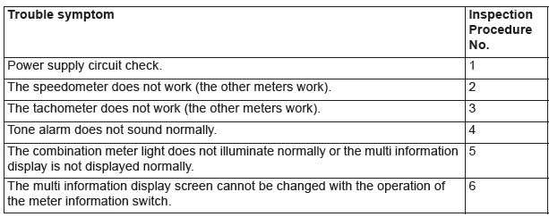
TROUBLE SYMPTOM CHART
CAUTION
- During troubleshooting, a DTC code associated with other system may be set when the ignition switch is turned on with connector(s) disconnected. On completion, confirm all systems for DTC code(s). If DTC code(s) are set, erase them all.
- When the combination meter is required to be replaced as a result of the troubleshooting, the current driving distance and number of elapsed days to be used for service reminder function must be entered into the meter after the replacement. Therefore, read "Integrated mileage for reminder," "Integrated days for reminder," "Mileage until Extra reminder," "Months until Extra reminder," and "Current Schedule" from the meter before the replacement using the special function of scan tool MB991958, and note them. For the operation method of scan tool MB991958, refer to P.54A. If "Integrated mileage for reminder" or "Integrated days for reminder" cannot be read by the scan tool MB991958, follow the method described below.
- For the driving distance for check warning, use the driving distance displayed on the multi information display.
- For the elapsed days for check warning, calculate the number of elapsed days from the delivery date to the customer (service remainder function start date) and current date.
READ NEXT:
 Symptom Procedures
Inspection Procedure 1: Power supply circuit check.
Combination Meter Power Supply Circuit
TECHNICAL DESCRIPTION (COMMENT)
If the odometer and trip meter are not displayed or all
the meter needles d
Check Procedure For Each Multi Information Display Screen
CHECK PROCEDURE FOR EACH MULTI INFORMATION DISPLAY SCREEN
<VEHICLES WITHOUT COLOR LIQUID CRYSTAL DISPLAY>
CAUTION
When there are TV towers, substations, or broadcasting
stations which emit stron
Service Reminder Function Set
HOW TO SET BY OPERATING THE SCAN
TOOL MB991958
CAUTION
If the combination meter needs to be
replaced, the current driving distance and
elapsed days must be entered into the meter
after the replac
SEE MORE:
Cylinder Head and Valves
REMOVAL AND INSTALLATION
Removal steps
Cylinder head bolt
Cylinder head bolt washer
Cylinder head bolt & washer
assembly
Cylinder head assembly
Cylinder head gasket
Engine oil control valve (OCV) filter
Retainer lock
Valve spring retainer
Valve spring
Intake valve
Retainer lock
Va
Important operation tips for the airconditioning
● Park the vehicle in the shade.
Parking in the hot sun will make the vehicle inside extremely hot, and it will
require more to cool the interior.
If it is necessary to park in the sun, open the windows for the first few minutes
of air conditioning operation to expel the hot air.
●
