Mitsubishi Outlander: Symptom Procedures
Inspection Procedure 1: Power supply circuit check.
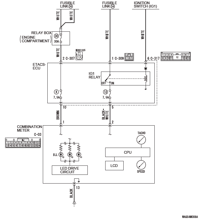
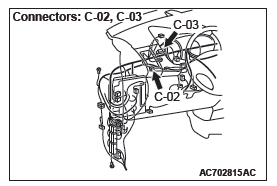
Combination Meter Power Supply Circuit
TECHNICAL DESCRIPTION (COMMENT)
If the odometer and trip meter are not displayed or all the meter needles do not move, power supply to the combination meter, or the combination meter itself may have a problem.
TROUBLESHOOTING HINTS
- The wiring harness or connectors may have loose, corroded, or damaged terminals, or terminals pushed back in the connector
- The combination meter may be defective
DIAGNOSIS
Required Special Tools:
- MB991223: Harness Set
- MB992006: Extra Fine Probe
- MB991958: Scan Tool (M.U.T.-III Sub Assembly)
- MB991824: Vehicles Communication Interface (V.C.I.)
- MB991827: M.U.T.-III USB Cable
- MB991910: M.U.T.-III Main Harness A (Vehicles with CAN communication system)
STEP 1. Using scan tool MB991958, read the combination meter diagnostic trouble code.
Check if DTC is set to the combination meter.
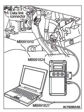
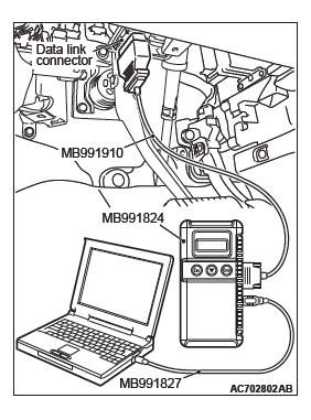
CAUTION To prevent damage to scan tool MB991958, always turn the ignition switch to the "LOCK" (OFF) position before connecting or disconnecting scan tool MB991958.
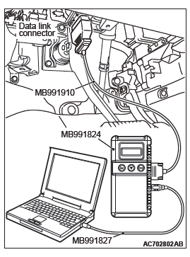
(1) Connect scan tool MB991958. Refer to "How to connect the Scan Tool (M.U.T.-III)".
(2) Turn the ignition switch from "LOCK" (OFF) position to "ON" position.
(3) Check if DTC is set.
(4) Turn the ignition switch to the "LOCK" (OFF) position.
Q: Is the DTC set?
YES : Troubleshoot the combination meter. NO : Go to Step 2.
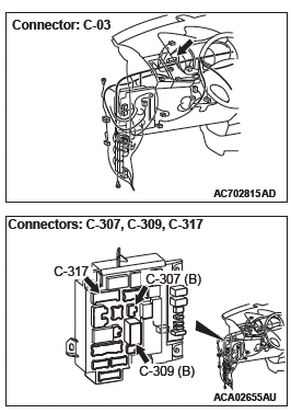
STEP 2. Check combination meter connector C-03 for loose, corroded or damaged terminals, or terminals pushed back in the connector.
Q: Is combination meter connector C-03 in good condition?
YES : Go to Step 3.
NO : Repair the defective connector.
STEP 3. Check the battery power supply circuit to the combination meter. Measure the voltage at combination meter connector C-03.
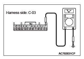
(1) Disconnect the connector, and measure at the wiring harness side.
(2) Turn the ignition switch to the LOCK (OFF) position.
(3) Measure the voltage between terminals 1 and ground.
- The voltage should measure approximately 12 volts (battery positive voltage).
Q: Is the measured voltage approximately 12 volts (battery positive voltage)?
YES : Go to Step 5.
NO : Go to Step 4.
STEP 4. Check the wiring harness between combination meter connector C-03 (terminal 1) and the fusible link (36).
- Check the power supply line (battery supply) for open circuit and short circuit.
NOTE: Also check ETACS-ECU connectors C-307 and C-317 for loose, corroded, or damaged terminals, or terminals pushed back in the connector. If ETACS-ECU connector C-307 or C-317 is damaged, repair or replace the damaged component( s) as described in GROUP 00E, Harness Connector Inspection.
Q: Is the wiring harness between combination meter connector C-03 (terminal 1) and the fusible link (36) in good condition?
YES : The trouble can be an intermittent malfunction.
NO : Repair the wiring harness.
STEP 5. Check the battery power supply circuit to the combination meter. Measure the voltage at combination meter connector C-03.
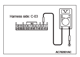
STEP 5. Check the battery power supply circuit to the combination meter. Measure the voltage at combination meter connector C-03.
(1) Disconnect the connector, and measure at the wiring harness side.
(2) Turn the ignition switch to the ON position.
(3) Measure the voltage between terminals 2 and ground.
- The voltage should measure approximately 12 volts (battery positive voltage).
Q: Is the measured voltage approximately 12 volts (battery positive voltage)?
YES : Go to Step 8.
NO : Go to Step 6.
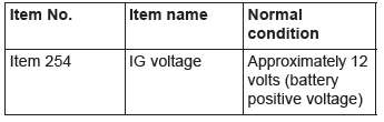
STEP 6. Using scan tool MB991958, check data list.
Check the input signal from the ignition switch (IG1) in the ETACS-ECU.
(1) Turn the ignition switch to the "ON" position.
(2) Check the ETACS data list.
- Turn the ignition switch to the "ON" position.
(3) Turn the ignition switch to the "LOCK" (OFF) position.
Q: Does the scan tool MB991958 display the item "IG voltage" is normal condition?
YES : Go to Step 7.
NO : Troubleshoot the ETACS-ECU. Refer to Inspection Procedure 2 "The ignition switch (IG1) signal is not received".
STEP 7. Check the wiring harness between combination meter connector C-03 (terminal 2) and the fusible link (34).
- Check the power supply line (battery supply) for open circuit and short circuit.
NOTE: Also check ETACS-ECU connectors C-309 and C-317 for loose, corroded, or damaged terminals, or terminals pushed back in the connector. If ETACS-ECU connector C-309 or C-317 is damaged, repair or replace the damaged component( s) as described in GROUP 00E, Harness Connector Inspection.
Q: Is the wiring harness between combination meter connector C-03 (terminal 2) and the fusible link (34) in good condition?
YES : The trouble can be an intermittent malfunction.
NO : Repair the wiring harness.
STEP 8. Check the ground circuit to the combination meter. Test at combination meter connector C-03.
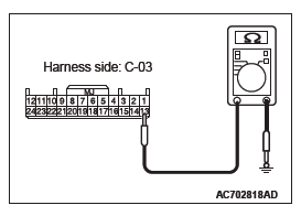
(1) Disconnect combination meter connector C-03 and measure the resistance available at the wiring harness side of the connector.
(2) Measure the resistance value between terminal 13 and ground.
- The resistance should be 2 ohms or less.
Q: Is the measured resistance 2 ohms or less?
YES : Go to Step 10.
NO : Go to Step 9.
STEP 9. Check the wiring harness between combination meter connector C-03 (terminal 13) and ground.
- Check the ground wire for open circuit.
Q: Is the wiring harness between combination meter connector C-03 (terminal 13) and ground in good condition?
YES : The trouble can be an intermittent malfunction.
NO : Repair the wiring harness.
STEP 10. Retest the system.
Check that the combination meter works normally.
Q: Is the check result satisfactory?
YES : The trouble can be an intermittent malfunction.
NO : Replace the combination meter.
Inspection Procedure 2: The speedometer does not work (the other meters work).
TECHNICAL DESCRIPTION (COMMENT)
If only the speedometer does not operate, the ABS-ECU <Vehicles without ASC> or ASC-ECU <Vehicles with ASC> and combination meter may have a problem.
TROUBLESHOOTING HINTS
- The ABS-ECU may be defective <Vehicles without ASC>
- The ASC-ECU may be defective <Vehicles with ASC>
- The combination meter may be defective
DIAGNOSIS
Required Special Tools:
- MB991958: Scan Tool (M.U.T.-III Sub Assembly)
- MB991824: Vehicles Communication Interface (V.C.I.)
- MB991827: M.U.T.-III USB Cable
- MB991910: M.U.T.-III Main Harness A (Vehicles with CAN communication system)
STEP 1. Using scan tool MB991958, diagnose the CAN bus line.
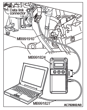
CAUTION To prevent damage to scan tool MB991958, always turn the ignition switch to the "LOCK" (OFF) position before connecting or disconnecting scan tool MB991958.
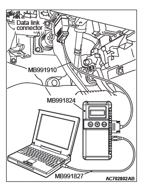
(1) Connect scan tool MB991958. Refer to "How to connect the Scan Tool (M.U.T.-III)".
(2) Turn the ignition switch to the "ON" position.
(3) Diagnose the CAN bus line.
(4) Turn the ignition switch to the "LOCK" (OFF) position.
Q: Is the CAN bus line found to be normal?
YES : Go to Step 2.
NO : Repair the CAN bus line.
STEP 2. Using scan tool MB991958, read the combination meter diagnostic trouble code.
Check if DTC is set to the combination meter.
Q: Is the DTC set?
YES : Troubleshoot the combination meter.
NO : Go to Step 3.
STEP 3. Using scan tool MB991958, read the ABS-ECU <Vehicles without ASC> or ASC-ECU <Vehicles with ASC> diagnostic trouble code.
Check if diagnostic trouble code is set to the ABS-ECU or ASC-ECU.
Q: Is the DTC set?
YES : Troubleshoot the ABS or ASC.
NO : Go to Step 4.
STEP 4. Using scan tool MB991958, check data list.
(1) Turn the ignition switch to the "ON" position.
(2) Check the data list on the combination meter.
- Item 80: Speedometer
- Should read vehicle speed.
(3) Turn the ignition switch to the "LOCK" (OFF) position.
Q: Does it read vehicle speed?
YES : Go to Step 5.
NO : Replace the combination meter.
STEP 5. Using scan tool MB991958, check actuator test.
(1) Turn the ignition switch to the "ON" position.
(2) Conduct the actuator test of the combination meter.
- Item 1: Speedometer
- The speedometer operates up to the set position.
(3) Turn the ignition switch to the "LOCK" (OFF) position.
Q: Is the check result normally?
YES : Go to Step 6.
NO : Replace the combination meter.
STEP 6. Retest the system.
Check that the speedometer works normally.
Q: Is the check result normal?
YES : The procedure is complete.
NO : Go to Step 1.
Inspection Procedure 3: The tachometer does not work (the other meters work).
TECHNICAL DESCRIPTION (COMMENT)
If only the tachometer does not operate, the ignition signal from the engine ECU may not be received or the combination meter may have a problem.
TROUBLESHOOTING HINTS
- The combination meter may be defective
- The engine control module may be defective
DIAGNOSIS
Required Special Tools:
- MB991958: Scan Tool (M.U.T.-III Sub Assembly)
- MB991824: Vehicles Communication Interface (V.C.I.)
- MB991827: M.U.T.-III USB Cable
- MB991910: M.U.T.-III Main Harness A (Vehicles with CAN communication system)
STEP 1. Using scan tool MB991958, diagnose the CAN bus line.
CAUTION To prevent damage to scan tool MB991958, always turn the ignition switch to the "LOCK" (OFF) position before connecting or disconnecting scan tool MB991958.
(1) Connect scan tool MB991958. Refer to "How to connect the Scan Tool (M.U.T.-III)".
(2) Turn the ignition switch to the "ON" position.
(3) Diagnose the CAN bus line.
(4) Turn the ignition switch to the "LOCK" (OFF) position.
Q: Is the CAN bus line found to be normal?
YES : Go to Step 2.
NO : Repair the CAN bus line.
STEP 2. Using scan tool MB991958, read the combination meter diagnostic trouble code.
Check if DTC is set to the combination meter.
Q: Is the DTC set?
YES : Troubleshoot the combination meter. NO : Go to Step 3.
STEP 3. Using scan tool MB991958, read the MFI diagnostic trouble code.
Check if DTC is set to the engine control module.
Q: Is the DTC set?
YES : Troubleshoot the MFI.
NO : Go to Step 4.
STEP 4. Using scan tool MB991958, check data list.
(1) Turn the ignition switch to the "ON" position.
(2) Check the data list on the combination meter.
- Item 87: Tachometer
- Should read engine speed.
(3) Turn the ignition switch to the "LOCK" (OFF) position.
Q: Does it read engine speed?
YES : Go to Step 5.
NO : Troubleshoot the MFI. Complete the engine troubleshooting, and then go to Step 6.
STEP 5. Using scan tool MB991958, check actuator test.
(1) Turn the ignition switch to the "ON" position.
(2) Conduct the actuator test of the combination meter.
- Item 2: Tachometer
- The tachometer operates up to the set position.
(3) Turn the ignition switch to the "LOCK" (OFF) position.
Q: Is the check result normally?
YES : Go to Step 6.
NO : Replace the combination meter.
STEP 6. Retest the system Check that the tachometer works normally.
Q: Is the check result normal?
YES : The procedure is complete.
NO : Go to Step 1.
Inspection Procedure 4: Tone alarm does not sound normally.
CAUTION Before replacing the combination meter, be sure to check that the power supply circuit, earth circuit, and communication circuit are normal.
TECHNICAL DESCRIPTION (COMMENT)
When the following signals are received via the CAN communication, the combination meter sounds the incorporated tone alarm according to the each pattern.
Seat belt reminder function
- Ignition switch ON signal
- Vehicle speed signal
- Driver's seat belt switch signal
- Front passenger's seat belt switch signal
Keyless operation key reminder tone alarm function (vehicles with KOS)
- Ignition switch OFF signal
- IG knob push switch ON signal
- Driver's door switch ON signal
Ignition key reminder tone alarm function (vehicles without KOS)
- Ignition switch OFF signal
- Key reminder switch OFF signal
- Driver's door switch ON signal
Light reminder tone alarm function
- Ignition switch OFF signal
- Lighting switch ON signal
- Driver's door switch ON signal
Door-ajar warning tone alarm function
- Ignition switch ON signal
- Any door switch or liftgate switch ON signal
- Vehicle speed signal
Freeze warning tone alarm
- Ignition switch ON signal
- Ambient temperature signal
Parking brake reminder tone alarm function
Ignition switch ON signal
- Parking brake switch ON signal
- Vehicle speed signal
Multi information display interrupt display tone alarm
- Display condition signal of information display from each warning (When there is a fixed tone alarm sounding pattern for each warning, that pattern has the priority.)
Meter information switch operation tone alarm
- ON signal for combination meter information switch
Turn-signal light tone alarm function
- Turn-signal light switch ON signal
Paddle shift cancel tone alarm, Theft-alarm function, ETACS-ECU function customize tone alarm, A/C operation tone alarm, audio operation tone alarm
- Sounding request signal from the ETACS-ECU
If the tone alarm does not sound normally, the connector( s) and wiring harness in the CAN bus lines, or each ECU or the combination meter may have a problem.
TROUBLESHOOTING HINTS
- The combination meter may be defective
- The each ECU may be defective
DIAGNOSIS
Required Special Tools:
- MB991958: Scan Tool (M.U.T.-III Sub Assembly)
- MB991824: Vehicle Communication Interface (V.C.I.)
- MB991827: M.U.T.-III USB Cable
- MB991910: M.U.T.-III Main Harness A (Vehicles with CAN communication system)
STEP 1. Using scan tool MB991958, diagnose the CAN bus line.
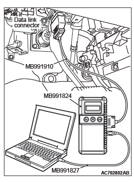
CAUTION To prevent damage to scan tool MB991958, always turn the ignition switch to the "LOCK" (OFF) position before connecting or disconnecting scan tool MB991958.
(1) Connect scan tool MB991958. Refer to "How to connect the Scan Tool (M.U.T.-III)".
(2) Turn the ignition switch to the "ON" position.
(3) Diagnose the CAN bus line.
(4) Turn the ignition switch to the "LOCK" (OFF) position.
Q: Is the CAN bus line found to be normal?
YES : Go to Step 2.
NO : Repair the CAN bus line.
STEP 2. Using scan tool MB991958, read the combination meter diagnostic trouble code.
Check if DTC is set to the combination meter.
Q: Is the DTC set?
YES : Refer to P.54A.
NO : Go to Step 3.
STEP 3. Using scan tool MB991958, read for any diagnostic trouble code.
Check if diagnosis code is set to the CVT, A/T, ABS, ASC, ETACS-ECU, WCM, KOS-ECU, AUDIO and A/C-ECU.
Q: Is the DTC set to the any of the above?
YES <Set to the CVT.> : Troubleshoot the CVT. Refer to GROUP 23A, Diagnosis.
YES <Set to the A/T.> : Troubleshoot the A/T. Refer to GROUP 23C, Diagnosis.
YES <Set to the ABS.> : Troubleshoot the ABS. Refer to GROUP 35B, Diagnosis.
YES <Set to the ASC.> : Troubleshoot the ASC. Refer to GROUP 35C, Diagnosis.
YES <Set to the ETACS.> : Troubleshoot the ETACS.
YES <Set to the WCM.> : Troubleshoot the WCM. Refer to GROUP 42C, diagnosis.
YES <Set to the KOS.> : Troubleshoot the KOS. Refer to GROUP 42B, Diagnosis.
YES <Set to the AUDIO.> : Troubleshoot the AUDIO.
YES <Set to the A/C.> : Troubleshoot the A/C. Refer to GROUP 55A, Manual A/C Diagnosis or GROUP 55B, Automatic A/C Diagnosis.
NO <The DTC is not set. (Vehicles without color liquid crystal display)> : Go to Step 4.
NO <The DTC is not set. (Vehicles with color liquid crystal display)> : Go to Step 5.
STEP 4. Using scan tool MB991958, check actuator test.
(1) Turn the ignition switch to the "ON" position.
(2) Conduct the actuator test of the combination meter.
- Item 12: Buzzer
(3) Turn the ignition switch to the "LOCK" (OFF) position.
Q: Is the check result normal?
YES : Go to Step 6.
NO : Replace the combination meter.
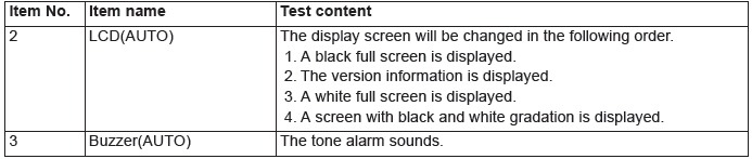
STEP 5. Check by scan tool MB991958 "Special Function".
Using scan tool MB991958, select "Test" from the special function of the combination meter. Execute the following item to check the buzzer.
- Item 3: Buzzer(AUTO)
Q: Is the check result normal?
YES : Go to Step 6.
NO : Replace the combination meter.
STEP 6. Retest the system.
Check that the tone alarm normally.
Q: Is the check result normal?
YES : The trouble can be an intermittent malfunction.
NO : Replace the combination meter.
Inspection Procedure 5: The combination meter light does not illuminate normally or the multi information display is not displayed normally.
CAUTION Before replacing the combination meter, be sure to check that the power supply circuit, earth circuit, and communication circuit are normal.
TECHNICAL DESCRIPTION (COMMENT)
When the signal from each ECU is received via the CAN communication, the combination meter illuminates the corresponding display light or warning light, or has the multi information display to display corresponding information.
If the lights do not illuminate or the multi information display does not display normally, the wiring harness and connector(s) in the CAN bus lines, or the each ECU or the combination meter may have a problem.
TROUBLESHOOTING HINTS
- The combination meter may be defective
- The each ECU may be defective
DIAGNOSIS
Required Special Tools:
- MB991958: Scan Tool (M.U.T.-III Sub Assembly)
- MB991824: Vehicle Communication Interface (V.C.I.)
- MB991827: M.U.T.-III USB Cable
- MB991910: M.U.T.-III Main Harness A (Vehicles with CAN communication system)
STEP 1. Using scan tool MB991958, diagnose the CAN bus line.
CAUTION To prevent damage to scan tool MB991958, always turn the ignition switch to the "LOCK" (OFF) position before connecting or disconnecting scan tool MB991958.
(1) Connect scan tool MB991958. Refer to "How to connect the Scan Tool (M.U.T.-III)".
(2) Turn the ignition switch to the "ON" position.
(3) Diagnose the CAN bus line.
(4) Turn the ignition switch to the "LOCK" (OFF) position.
Q: Is the CAN bus line found to be normal?
YES : Go to Step 2.
NO : Repair the CAN bus line.
STEP 2. Using scan tool MB991958, read the combination meter diagnostic trouble code.
Check again if the DTC is set to the combination meter.
Q: Is the DTC set?
YES : Refer to P.54A.
NO : Go to Step 3.
STEP 3. Using scan tool MB991958, read for any diagnostic trouble code.
Check again if the DTC is set to the MFI, A/T, AWD, WCM, KOS, ABS, ASC, SRS, ETACS and A/C.
Q: Is the DTC set to the any of the above?
YES <Set to the MFI.> : Troubleshoot the MFI. Refer to GROUP 13A, Diagnosis <2.4 L engine> or GROUP 13B, Diagnosis <3.0 L engine>.
YES <Set to the CVT.> : Troubleshoot the CVT. Refer to GROUP 23A, Diagnosis.
YES <Set to the A/T.> : Troubleshoot the A/T. Refer to GROUP 23C, Diagnosis.
YES <Set to the AWD.> : Troubleshoot the AWD. Refer to GROUP 27C, Diagnosis.
YES <Set to the ABS.> : Troubleshoot the ABS. Refer to GROUP 35B, Diagnosis.
YES <Set to the ASC.> : Troubleshoot the ASC. Refer to GROUP 35C, Diagnosis.
YES <Set to the WCM.> : Troubleshoot the WCM. Refer to GROUP 42C, diagnosis.
YES <Set to the KOS.> : Troubleshoot the KOS. Refer to GROUP 42B, Diagnosis.
YES <Set to the SRS.> : Troubleshoot the SRS. Refer to GROUP 52B, Diagnosis.
YES <Set to the ETACS.> : Troubleshoot the ETACS.
YES <Set to the A/C.> : Troubleshoot the A/C. Refer to GROUP 55A, Manual A/C Diagnosis or GROUP 55B, Automatic A/C Diagnosis.
STEP 4. Using scan tool MB991958, check actuator test.
(1) Turn the ignition switch to the "ON" position.
(2) Conduct the actuator test of the combination meter.
- Item 7: Indicator1
- Item 8: Indicator2
- Item 9: Indicator3
- Item 11: Shift indicator
- Item 13: Indicator4
(3) Turn the ignition switch to the "LOCK" (OFF) position.
Q: Is the check result normal?
YES : Go to Step 7.
NO : Replace the combination meter.
STEP 5. Using scan tool MB991958, check actuator test.
(1) Turn the ignition switch to the "ON" position.
(2) Conduct the actuator test of the combination meter.
- Item 7: Indicator1
- Item 8: Indicator2
- Item 9: Indicator3
- Item 10: Indicator4
(3) Turn the ignition switch to the "LOCK" (OFF) position.
Q: Is the check result normal?
YES : Go to Step 6.
NO : Replace the combination meter.
STEP 6. Check by scan tool MB991958 "Special Function".
Using scan tool MB991958, select "Test" from the special function of the combination meter. Execute the following item to check the liquid crystal display.
- Item 2: LCD(AUTO)
Q: Is the check result normal?
YES : Go to Step 7.
NO : Replace the combination meter.
STEP 7. Retest the system.
Check that display lights or warning lights are illuminated normally, or multi information display is displayed normally.
Q: Is the check result normal?
YES : The trouble can be an intermittent malfunction.
NO : Replace the combination meter.
Inspection Procedure 6: The multi information display screen cannot be changed with the operation of the meter information switch.
Meter Information Switch Circuit
CAUTION Before replacing the combination meter, be sure to check that the power supply circuit, ground circuit, and communication circuit are normal.
TECHNICAL DESCRIPTION (COMMENT)
When the signal from the meter information switch is received, the combination meter switches the multi information display screen. If the multi information display screen does not switch normally, the meter information switch, wiring harness, connector(s), or combination meter may have a problem.
TROUBLESHOOTING HINTS
- The meter information switch may be defective
- The combination meter may be defective
- The wiring harness or connectors may have loose, corroded, or damaged terminals, or terminals pushed back in the connector
DIAGNOSIS
Required Special Tools:
- MB991223: Harness Set
- MB992006: Extra Fine Probe
- MB991958: Scan Tool (M.U.T.-III Sub Assembly)
- MB991824: Vehicles Communication Interface (V.C.I.)
- MB991827: M.U.T.-III USB Cable
- MB991910: M.U.T.-III Main Harness A (Vehicles with CAN communication system)
STEP 1. Using scan tool MB991958, read the combination meter diagnostic trouble code.
Check if DTC is set to the combination meter.
CAUTION To prevent damage to scan tool MB991958, always turn the ignition switch to the "LOCK" (OFF) position before connecting or disconnecting scan tool MB991958.
(1) Connect scan tool MB991958. Refer to "How to connect the Scan Tool (M.U.T.-III)".
(2) Turn the ignition switch to the "ON" position.
(3) Turn the ignition switch from "LOCK" (OFF) position to "ON" position.
(4) Check if DTC is set.
Q: Is the DTC set?
YES : Refer to P.54A.
NO : Go to Step 2.
STEP 2. Check meter information switch connector C-02 for loose, corroded or damaged terminals, or terminals pushed back in the connector.
Q: Is meter information switch connector C-02 in good condition?
YES : Go to Step 3.
NO : Repair the defective connector.
STEP 3. Check the meter information switch.
Check the meter information switch. Q: Is the check result normal?
YES : Go to Step 4.
NO : Replace the meter information switch.
STEP 4. Check the wiring harness between meter information switch connector C-02 (terminal 4) and ground.
- Check the ground wire for open circuit.
Q: Is the wiring harness between fuel meter information switch connector C-02 (terminal 4) and ground in good condition?
YES : Go to Step 5.
NO : Repair the wiring harness.
STEP 5. Check combination meter connector C-03 for loose, corroded or damaged terminals, or terminals pushed back in the connector.
Q: Is combination meter connector C-03 in good condition?
YES : Go to Step 6.
NO : Repair the defective connector.
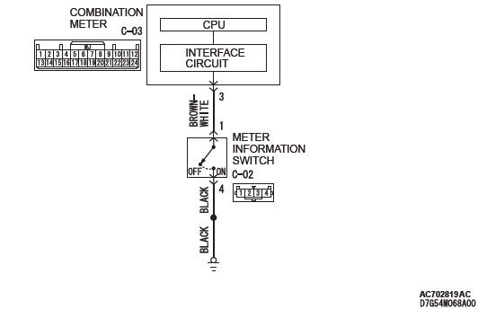
STEP 6. Check the wiring harness between meter information switch connector C-02 (terminal 1) and combination meter connector C-03 (terminal 3).
- Check the output line for open circuit.
Q: Are the wiring harness between meter information switch connector C-02 (terminal 1) and combination meter connector C-03 (terminal 3) in good condition?
YES : Go to Step 7.
NO : Repair the wiring harness.
STEP 7. Retest the system.
Check that the multi information display screen switches normally when the meter information switch is operated.
Q: Is the check result normal?
YES : The trouble can be an intermittent malfunction.
NO : Replace the combination meter.
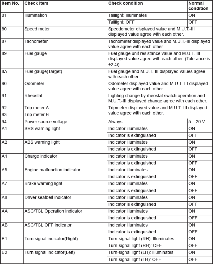
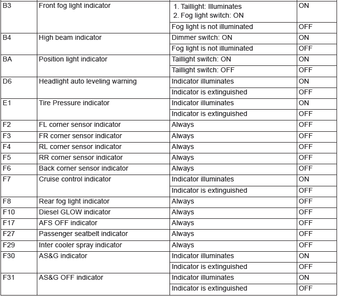
SERVICE DATA
NOTE: For some information result read out by the ECU, the specific items may not be displayed.
ACTUATOR TEST TABLE
ACTUATOR TEST
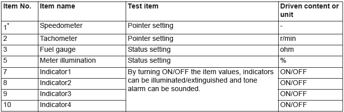
NOTE: *: Depending on the main scale of the speedometer, the unit that can be tested changes. Unit is displayed as "−" on the scan tool MB991958 screen.
TEST (SPECIAL FUNCTION)
READ NEXT:
 Check Procedure For Each Multi Information Display Screen
CHECK PROCEDURE FOR EACH MULTI INFORMATION DISPLAY SCREEN
<VEHICLES WITHOUT COLOR LIQUID CRYSTAL DISPLAY>
CAUTION
When there are TV towers, substations, or broadcasting
stations which emit stron
Service Reminder Function Set
HOW TO SET BY OPERATING THE SCAN
TOOL MB991958
CAUTION
If the combination meter needs to be
replaced, the current driving distance and
elapsed days must be entered into the meter
after the replac
SEE MORE:
Tools and jack
Storage
The tools and jack are stowed on the right side of the luggage area.
The storage location of the tools and jack should be remembered in case of an
emergency.
1- Jack.
2- Tools.
Tools
1- Tool case.
2- Wheel nut wrench.
3- Jack bar.
4- Towing hook.
Jack
To remove
1. Turn th
On-vehicle Service
A/T CONTROL COMPONENT LAYOUT
ESSENTIAL SERVICE
TRANSMISSION FLUID CHECK
1. Drive the vehicle until the transmission fluid temperature
rises to the normal operating temperature [70 − 80ºC (158 −
176ºF) ].
NOTE: The transmission fluid temperature is measured with
scan tool MB991958
