Mitsubishi Outlander: Diagnosis
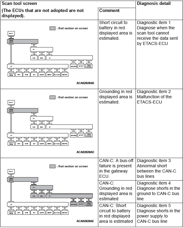
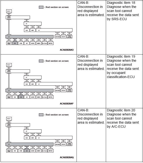
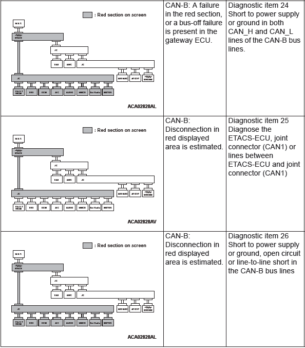
CAN BUS DIAGNOSTICS TABLE
CAUTION A diagnostic trouble code may not also be set in the CAN-B lines under the conditions below. If no diagnostic trouble code has been set due to electrical noise, confirm diagnostic item 26.
- Open circuit at the CAN_H side of the CAN-B bus lines
- Open circuit at the CAN_L side of the CAN-B bus line
- Short to ground at the CAN_H side of the CAN-B bus line
CAUTION During diagnosis, a diagnostic trouble code associated with another system may be set when the ignition switch is turned on with connector(s) disconnected. After completing the repair, confirm all systems for diagnostic trouble code(s). If diagnostic trouble code(s) are set, erase them all.
This diagnosis applies only to the CAN bus lines. If a different system is defective, proceed to the applicable diagnosis section for each system. Observe the diagnostic procedure below only when the CAN bus line is defective.

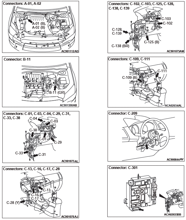
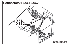
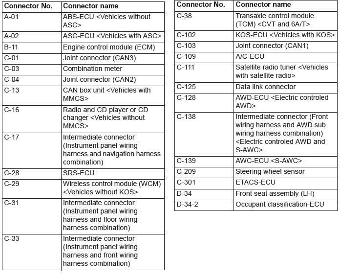
CAN-RELATED CONNECTOR POSITION
READ NEXT:
 Diagnostic Item 1-5
DIAGNOSTIC ITEM 1: Diagnose when the scan tool cannot receive the data
sent by ETACS-ECU
CAUTION
When servicing a CAN bus line, ground yourself by touching a metal object such
as an unpainted
water
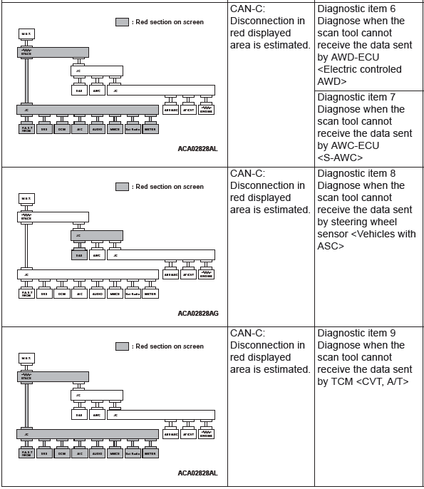
Diagnostic Item 6-13
DIAGNOSTIC ITEM 6: Diagnose when the scan tool cannot receive the data
sent by AWD-ECU
<Electronic controlled AWD>.
CAUTION
When servicing a CAN bus line, ground yourself by touching a metal ob
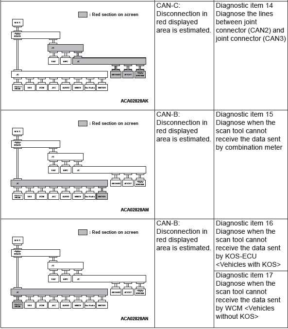
Diagnostic Item 14-23
DIAGNOSTIC ITEM 14: Diagnose the lines between joint connector (CAN2)
and joint connector
(CAN3).
CAUTION
When servicing a CAN bus line, ground yourself by touching a metal object such
as an unpain
SEE MORE:
How To Diagnose (Electrical)
HOW TO DIAGNOSE
The most important point in troubleshooting is to
determine "Probable Cause". Once the probable
causes are determined, parts to be checked can be
limited to those associated with such probable
causes. The determination of the probable causes
must be based on a theory and be supported
Manual transmission
The shift pattern is shown on the gearshift lever knob. Be sure to always fully
depress the clutch pedal before attempting to shift the lever.
CAUTION:
● Do not put the gearshift lever into the reverse position while the vehicle
is moving forward. Doing so could damage the transmission
