Mitsubishi Outlander: Diagnostic Item 14-23
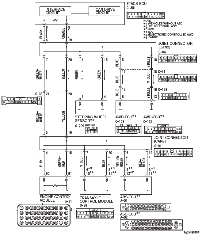
DIAGNOSTIC ITEM 14: Diagnose the lines between joint connector (CAN2) and joint connector (CAN3).
CAUTION When servicing a CAN bus line, ground yourself by touching a metal object such as an unpainted water pipe. If you fail to do so, a component connected to the CAN bus line may be damaged.
CAN Communication Circuit
FUNCTION
If a failure is present in the wiring harness between the joint connector (CAN2) and the joint connector (CAN3), this diagnosis result will be set.
TROUBLE JUDGMENT CONDITIONS
If a communication flag is not set for some of the ECUs on the CAN-C line, the ETACS-ECU determines that there is a failure.
TROUBLESHOOTING HINTS
- Malfunction of the connector [joint connector (CAN2), joint connector (CAN3) or intermediate connector failed]
- Malfunction of the wiring harness [open circuit between joint connector (CAN2) and joint connector (CAN3) ]
DIAGNOSIS
Required Special Tools:
- MB991223: Harness Set
- MB992006: Extra Fine Probe
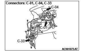
STEP 1. Check joint connector (CAN2) C-04, joint connector (CAN3) C-01 and intermediate connector C-33 for loose, corroded or damaged terminals, or terminals pushed back in the connector.
CAUTION The strand end of the twisted wire should be within 10 cm (4 inches) from the connector.
Q: Are joint connector (CAN2) C-04, joint connector (CAN3) C-01 and intermediate connector C-33 in good condition?
YES : Go to Step 2.
NO : Repair the damaged parts.
STEP 2. Check the wiring harness between joint connector (CAN2) C-04 and joint connector (CAN3) C-01 for open circuit.
CAUTION Strictly observe the specified wiring harness repair procedure.
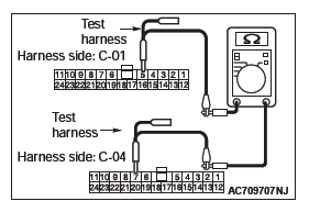
(1) Disconnect joint connector (CAN2) C-04 and joint connector (CAN3) C-01, and check the wiring harness.
(2) Check the wiring harness between joint connector (CAN2) C-04 (terminal No.7) and joint connector (CAN3) C-01 (terminal No.5)
OK: Continuity exists (2 ohms or less)
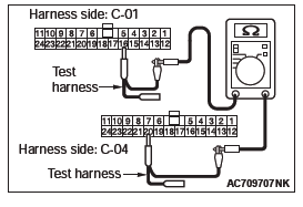
(3) Check the wiring harness between joint connector (CAN2) C-04 (terminal No.20) and joint connector (CAN3) C-01 (terminal No.16)
OK: Continuity exists (2 ohms or less)
Q: Is the wiring harness between joint connector (CAN2) C-04 and joint connector (CAN3) C-01 in good condition?
YES : The trouble can be an intermittent malfunction.
NO : Repair the wiring harness between joint connector (CAN2) C-04 and joint connector (CAN3) C-01.
DIAGNOSTIC ITEM 15: Diagnose when the scan tool cannot receive the data sent by combination meter.
CAUTION When servicing a CAN bus line, ground yourself by touching a metal object such as an unpainted water pipe. If you fail to do so, a component connected to the CAN bus line may be damaged.
CAN Communication Circuit
FUNCTION
If the scan tool MB991958 cannot communicate with the combination meter, this diagnosis result will be set.
TROUBLE JUDGMENT CONDITIONS
If a communication flag is not set for the combination meter, the ETACS-ECU determines that there is a failure.
TROUBLESHOOTING HINTS
- Malfunction of the connector [joint connector (CAN1), combination meter connector improperly connected]
- Malfunction of the wiring harness [open circuit between the combination meter connector and the joint connector (CAN1), power supply circuit to the combination meter]
- Malfunction of the combination meter
DIAGNOSIS
Required Special Tools:
- MB991223: Harness Set
- MB992006: Extra Fine Probe
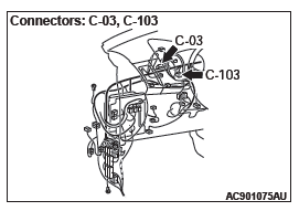
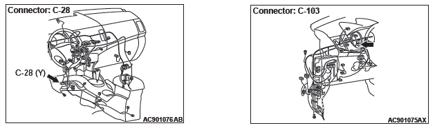
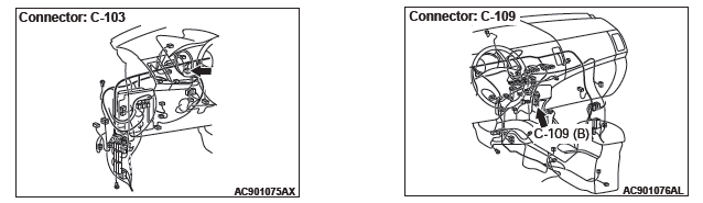
STEP 1. Check joint connector (CAN1) C-103 and combination meter connector C-03 for loose, corroded or damaged terminals, or terminals pushed back in the connector.
CAUTION The strand end of the twisted wire should be within 10 cm (4 inches) from the connector.
Q: Are joint connector (CAN1) C-103 and combination meter connector C-03 in good condition?
YES : Go to Step 2.
NO : Repair the damaged parts.
STEP 2. Check the wiring harness between joint connector (CAN1) C-103 and combination meter connector C-03 for open circuit.
CAUTION Strictly observe the specified wiring harness repair procedure.
(1) Disconnect joint connector (CAN1) C-103 and combination meter connector C-03, and check the wiring harness.
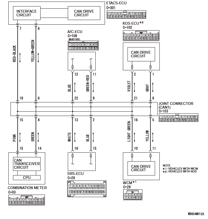
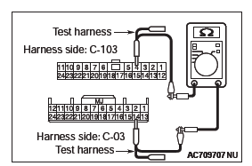
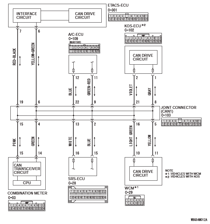
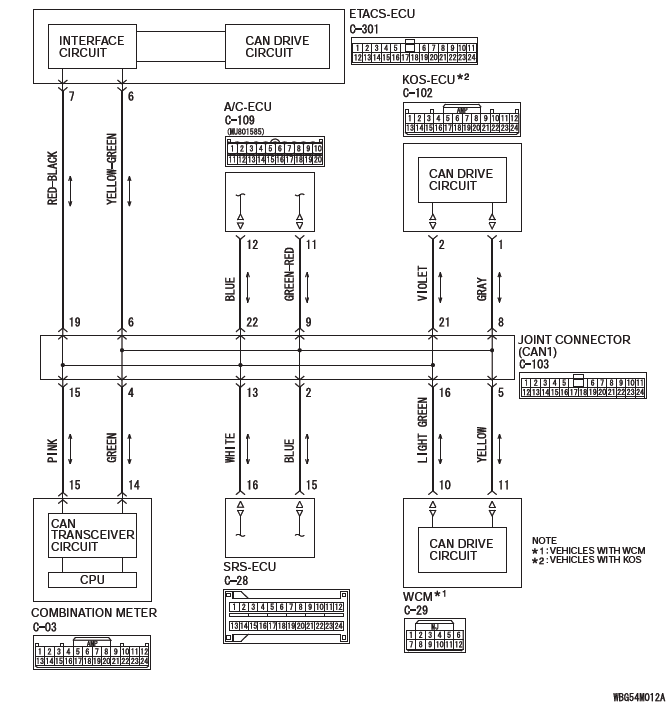
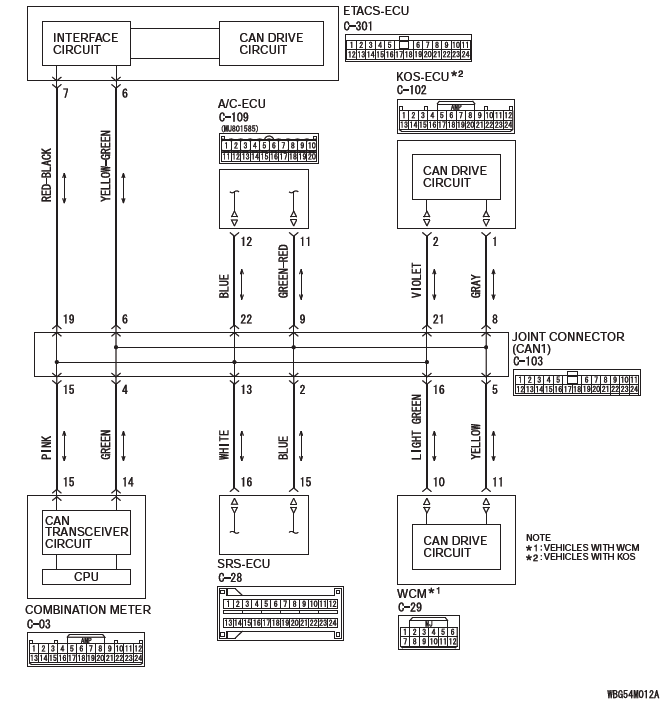
(2) Check the wiring harness between joint connector (CAN1) C-103 (terminal No.4) and combination meter connector C-03 (terminal No.14)
OK: Continuity exists (2 ohms or less)
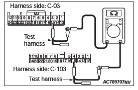
(3) Check the wiring harness between joint connector (CAN1) C-103 (terminal No.15) and combination meter connector C-03 (terminal No.15)
OK: Continuity exists (2 ohms or less)
Q: Is the wiring harness between joint connector (CAN1) C-103 and combination meter connector C-03 in good condition?
YES : Check the power supply circuit of the combination meter. NO : Repair the wiring harness between joint connector (CAN1) C-103 and combination meter connector C-03.
DIAGNOSTIC ITEM 16: Diagnose when the scan tool cannot receive the data sent by KOS-ECU <vehicles with KOS>.
CAUTION When servicing a CAN bus line, ground yourself by touching a metal object such as an unpainted water pipe. If you fail to do so, a component connected to the CAN bus line may be damaged.
CAN Communication Circuit
FUNCTION
If the scan tool MB991958 cannot communicate with the KOS-ECU, this diagnosis result will be set.
TROUBLE JUDGMENT CONDITIONS
If a communication flag is not set for the KOS-ECU, the ETACS-ECU determines that there is a failure.
TROUBLESHOOTING HINTS
- Malfunction of the connector [joint connector (CAN1), KOS-ECU connector improperly connected]
- Malfunction of the wiring harness [open circuit between the KOS-ECU connector and the joint connector (CAN1), power supply circuit to the KOS-ECU]
- Malfunction of the KOS-ECU
DIAGNOSIS
Required Special Tools:
- MB991223: Harness Set
- MB992006: Extra Fine Probe
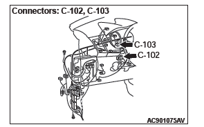
STEP 1. Check joint connector (CAN1) C-103 and KOS-ECU connector C-102 for loose, corroded or damaged terminals, or terminals pushed back in the connector.
CAUTION The strand end of the twisted wire should be within 10 cm (4 inches) from the connector.
Q: Are joint connector (CAN1) C-103 and KOS-ECU connector C-102 in good condition?
YES : Go to Step 2.
NO : Repair the damaged parts.
STEP 2. Check the wiring harness between joint connector (CAN1) C-103 and KOS-ECU connector C-102 for open circuit.
CAUTION Strictly observe the specified wiring harness repair procedure.
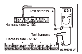
(1) Disconnect joint connector (CAN1) C-103 and KOS-ECU connector C-102, and check the wiring harness.
(2) Check the wiring harness between joint connector (CAN1) C-103 (terminal No.8) and KOS-ECU connector C-102 (terminal No.1)
OK: Continuity exists (2 ohms or less)
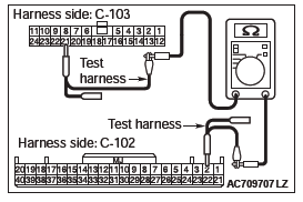
(3) Check the wiring harness between joint connector (CAN1) C-103 (terminal No.21) and KOS-ECU connector C-102 (terminal No.2)
OK: Continuity exists (2 ohms or less)
Q: Is the wiring harness between joint connector (CAN1) C-103 and KOS-ECU connector C-102 in good condition?
YES : Check the power supply circuit of the KOS-ECU.
NO : Repair the wiring harness between joint connector (CAN1) C-103 and KOS-ECU connector C-102.
DIAGNOSTIC ITEM 17: Diagnose when the scan tool cannot receive the data sent by WCM <vehicles without KOS>.
CAUTION When servicing a CAN bus line, ground yourself by touching a metal object such as an unpainted water pipe. If you fail to do so, a component connected to the CAN bus line may be damaged.
CAN Communication Circuit
FUNCTION
If the scan tool MB991958 cannot communicate with the WCM, this diagnosis result will be set.
TROUBLE JUDGMENT CONDITIONS
If a communication flag is not set for the WCM, the ETACS-ECU determines that there is a failure.
TROUBLESHOOTING HINTS
- Malfunction of the connector [joint connector (CAN1), WCM connector improperly connected]
- Malfunction of the wiring harness [open circuit between the WCM connector and the joint connector (CAN1), power supply circuit to the WCM]
- Malfunction of the WCM
DIAGNOSIS
Required Special Tools:
- MB991223: Harness Set
- MB992006: Extra Fine Probe
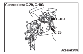
STEP 1. Check joint connector (CAN1) C-103 and WCM connector C-29 for loose, corroded or damaged terminals, or terminals pushed back in the connector.
CAUTION The strand end of the twisted wire should be within 10 cm (4 inches) from the connector.
Q: Are joint connector (CAN1) C-103 and WCM connector C-29 in good condition?
YES : Go to Step 2.
NO : Repair the damaged parts.
STEP 2. Check the wiring harness between joint connector (CAN1) C-103 and WCM connector C-29 for open circuit.
CAUTION Strictly observe the specified wiring harness repair procedure.
(1) Disconnect joint connector (CAN1) C-103 and WCM connector C-29, and check the wiring harness.
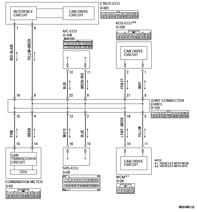
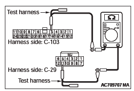
(2) Check the wiring harness between joint connector (CAN1) C-103 (terminal No.5) and WCM connector C-29 (terminal No.11)
OK: Continuity exists (2 ohms or less)
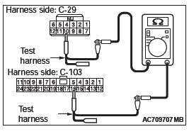
(3) Check the wiring harness between joint connector (CAN1) C-103 (terminal No.16) and WCM connector C-29 (terminal No.2)
OK: Continuity exists (2 ohms or less)
Q: Is the wiring harness between joint connector (CAN1) C-103 and WCM connector C-29 in good condition?
YES : Check the power supply circuit of the WCM. NO : Repair the wiring harness between joint connector (CAN1) C-103 and WCM connector C-29.
DIAGNOSTIC ITEM 18: Diagnose when the scan tool cannot receive the data sent by SRS-ECU.
CAUTION When servicing a CAN bus line, ground yourself by touching a metal object such as an unpainted water pipe. If you fail to do so, a component connected to the CAN bus line may be damaged.
CAN Communication Circuit
FUNCTION
If the scan tool MB991958 cannot communicate with the SRS-ECU, this diagnosis result will be set.
TROUBLE JUDGMENT CONDITIONS
If a communication flag is not set for the SRS-ECU, the ETACS-ECU determines that there is a failure.
TROUBLESHOOTING HINTS
- Malfunction of the connector [joint connector (CAN1), SRS-ECU connector improperly connected]
- Malfunction of the wiring harness [open circuit between the SRS-ECU connector and the joint connector (CAN1), power supply circuit to the SRS-ECU]
- Malfunction of the SRS-ECU
DIAGNOSIS
Required Special Tools:
- MB991223: Harness Set
- MB992006: Extra Fine Probe
STEP 1. Check joint connector (CAN1) C-103 and SRS-ECU connector C-28 for loose, corroded or damaged terminals, or terminals pushed back in the connector.
CAUTION The strand end of the twisted wire should be within 10 cm (4 inches) from the connector.
Q: Are joint connector (CAN1) C-103 and SRS-ECU connector C-28 in good condition?
YES : Go to Step 2.
NO : Repair the damaged parts.
STEP 2. Check the wiring harness between joint connector (CAN1) C-103 and SRS-ECU connector C-28 for open circuit.
CAUTION Strictly observe the specified wiring harness repair procedure.
(1) Disconnect joint connector (CAN1) C-103 and SRS-ECU connector C-28, and check the wiring harness.
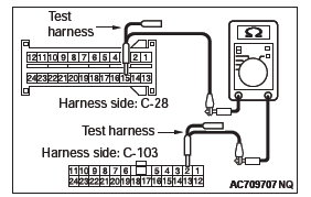
(2) Check the wiring harness between joint connector (CAN1) C-103 (terminal No.2) and SRS-ECU connector C-28 (terminal No.15)
OK: Continuity exists (2 ohms or less)
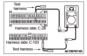
(3) Check the wiring harness between joint connector (CAN1) C-103 (terminal No.13) and SRS-ECU connector C-28 (terminal No.16)
OK: Continuity exists (2 ohms or less)
Q: Is the wiring harness between joint connector (CAN1) C-103 and SRS-ECU connector C-28 in good condition?
YES : Check the power supply circuit of the SRS-ECU.
NO : Repair the wiring harness between joint connector (CAN1) C-103 and SRS-ECU connector C-28.
DIAGNOSTIC ITEM 19: Diagnose when the scan tool cannot receive the data sent by occupant classification-ECU.
CAUTION When servicing a CAN bus line, ground yourself by touching a metal object such as an unpainted water pipe. If you fail to do so, a component connected to the CAN bus line may be damaged.
CAN Communication Circuit
FUNCTION
If the scan tool MB991958 cannot communicate with the occupant classification-ECU, this diagnosis result will be set.
TROUBLE JUDGMENT CONDITIONS
If a communication flag is not set for the occupant classification-ECU, the ETACS-ECU determines that there is a failure.
TROUBLESHOOTING HINTS
- Malfunction of the connector [joint connector (CAN1), occupant classification-ECU connector improperly connected]
- Malfunction of the wiring harness [open circuit between the occupant classification-ECU connector and the joint connector (CAN1), power supply circuit to the occupant classification-ECU]
- Malfunction of the occupant classification-ECU
DIAGNOSIS
Required Special Tools:
- MB991223: Harness Set
- MB992006: Extra Fine Probe
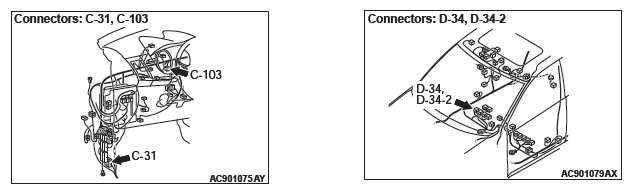
STEP 1. Check joint connector (CAN1) C-103, occupant classification-ECU connector D-34-2, front seat assembly (LH) connector D-34 and intermediate connector C-31 for loose, corroded or damaged terminals, or terminals pushed back in the connector.
CAUTION The strand end of the twisted wire should be within 10 cm (4 inches) from the connector.
Q: Are joint connector (CAN1) C-103, occupant classification-ECU connector D-34-2, front seat assembly (LH) connector D-34 and intermediate connector C-31 in good condition?
YES : Go to Step 2.
NO : Repair the damaged parts.
STEP 2. Check the wiring harness between joint connector (CAN1) C-103 and occupant classification-ECU connector D-34-2 for open circuit.
CAUTION Strictly observe the specified wiring harness repair procedure.
(1) Disconnect joint connector (CAN1) C-103 and occupant classification-ECU connector D-34-2, and check the wiring harness.
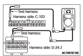
(2) Check the wiring harness between joint connector (CAN1) C-103 (terminal No.11) and occupant classification-ECU connector D-34-2 (terminal No.24)
OK: Continuity exists (2 ohms or less)
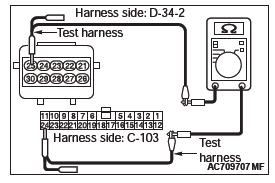
(3) Check the wiring harness between joint connector (CAN1) C-103 (terminal No.24) and occupant classification-ECU connector D-34-2 (terminal No.25)
OK: Continuity exists (2 ohms or less)
Q: Is the wiring harness between joint connector (CAN1) C-103 and occupant classification-ECU connector D-34-2 in good condition?
YES : Check the power supply circuit of the occupant classification-ECU. NO : Repair the wiring harness between joint connector (CAN1) C-103 and occupant classification-ECU connector D-34-2.
DIAGNOSTIC ITEM 20: Diagnose when the scan tool cannot receive the data sent by A/C-ECU.
CAUTION When servicing a CAN bus line, ground yourself by touching a metal object such as an unpainted water pipe. If you fail to do so, a component connected to the CAN bus line may be damaged.
CAN Communication Circuit
FUNCTION
If the scan tool MB991958 cannot communicate with the A/C-ECU, this diagnosis result will be set.
TROUBLE JUDGMENT CONDITIONS
If a communication flag is not set for the A/C-ECU, the ETACS-ECU determines that there is a failure.
TROUBLESHOOTING HINTS
- Malfunction of the connector [joint connector (CAN1), A/C-ECU connector improperly connected]
- Malfunction of the wiring harness [open circuit between the A/C-ECU connector and the joint connector (CAN1), power supply circuit to the A/C-ECU]
- Malfunction of the A/C-ECU
DIAGNOSIS
Required Special Tools:
- MB991223: Harness Set
- MB992006: Extra Fine Probe
STEP 1. Check joint connector (CAN1) C-103 and A/C-ECU connector C-109 for loose, corroded or damaged terminals, or terminals pushed back in the connector.
CAUTION The strand end of the twisted wire should be within 10 cm (4 inches) from the connector.
Q: Are joint connector (CAN1) C-103 and A/C-ECU connector C-109 in good condition?
YES : Go to Step 2.
NO : Repair the damaged parts.
STEP 2. Check the wiring harness between joint connector (CAN1) C-103 and A/C-ECU connector C-109 for open circuit.
CAUTION Strictly observe the specified wiring harness repair procedure.
(1) Disconnect joint connector (CAN1) C-103 and A/C-ECU connector C-109, and check the wiring harness.
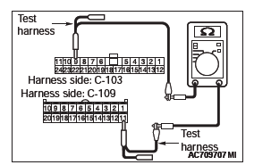
(2) Check the wiring harness between joint connector (CAN1) C-103 (terminal No.9) and A/C-ECU connector C-109 (terminal No.11)
OK: Continuity exists (2 ohms or less)
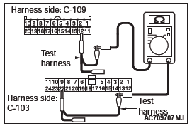
(3) Check the wiring harness between joint connector (CAN1) C-103 (terminal No.22) and A/C-ECU connector C-109 (terminal No.12)
OK: Continuity exists (2 ohms or less)
Q: Is the wiring harness between joint connector (CAN1) C-103 and A/C-ECU connector C-109 in good condition?
YES : Check the power supply circuit of the A/C-ECU.
NO : Repair the wiring harness between joint connector (CAN1) C-103 and A/C-ECU connector C-109.
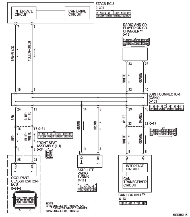
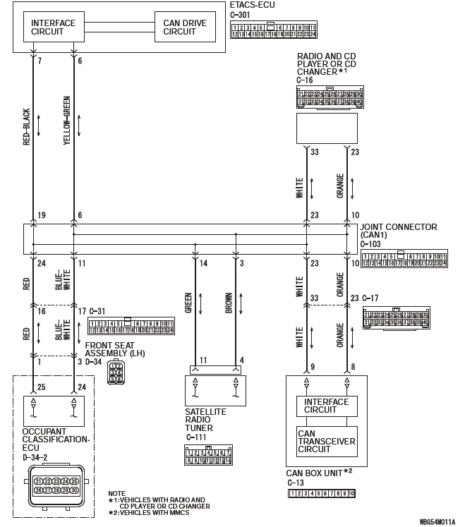
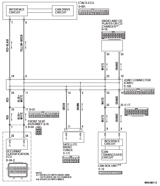
DIAGNOSTIC ITEM 21: Diagnose when the scan tool cannot receive the data sent by radio and CD player <vehicles with radio and CD player> or radio and CD changer <vehicles with radio and CD changer>.
CAUTION When servicing a CAN bus line, ground yourself by touching a metal object such as an unpainted water pipe. If you fail to do so, a component connected to the CAN bus line may be damaged.
CAN Communication Circuit
FUNCTION
If the scan tool MB991958 cannot communicate with the radio and CD player or radio and CD changer, this diagnosis result will be set.
TROUBLE JUDGMENT CONDITIONS
If a communication flag is not set for the radio and CD player or radio and CD changer, the ETACS-ECU determines that there is a failure.
TROUBLESHOOTING HINTS
- Malfunction of the connector [joint connector (CAN1), radio and CD player or radio and CD changer connector improperly connected]
- Malfunction of the wiring harness [open circuit between the radio and CD player or radio and CD changer connector and the joint connector (CAN1), power supply circuit to the radio and CD player or radio and CD changer]
- Malfunction of the radio and CD player or radio and CD changer
DIAGNOSIS
Required Special Tools:
- MB991223: Harness Set
- MB992006: Extra Fine Probe
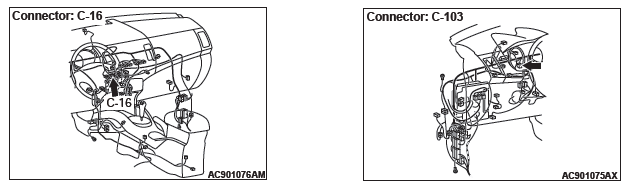
STEP 1. Check joint connector (CAN1) C-103 and radio and CD player or radio and CD changer connector C-16 for loose, corroded or damaged terminals, or terminals pushed back in the connector.
CAUTION The strand end of the twisted wire should be within 10 cm (4 inches) from the connector.
Q: Are joint connector (CAN1) C-103 and radio and CD player or radio and CD changer connector C-16 in good condition?
YES : Go to Step 2.
NO : Repair the damaged parts.
STEP 2. Check the wiring harness between joint connector (CAN1) C-103 and radio and CD player or radio and CD changer connector C-16 for open circuit.
CAUTION Strictly observe the specified wiring harness repair procedure.
(1) Disconnect joint connector (CAN1) C-103 and radio and CD player or radio and CD changer connector C-16, and check the wiring harness.
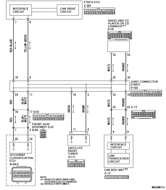
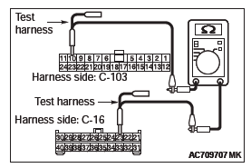
(2) Check the wiring harness between joint connector (CAN1) C-103 (terminal No.10) and radio and CD player or radio and CD changer connector C-16 (terminal No.23)
OK: Continuity exists (2 ohms or less)
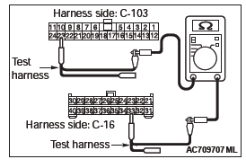
(3) Check the wiring harness between joint connector (CAN1) C-103 (terminal No.23) and radio and CD player or radio and CD changer connector C-16 (terminal No.33)
OK: Continuity exists (2 ohms or less)
Q: Is the wiring harness between joint connector (CAN1) C-103 and radio and CD player or radio and CD changer connector C-16 in good condition?
YES : Check the power supply circuit of the radio and CD player or radio and CD changer. NO : Repair the wiring harness between joint connector (CAN1) C-103 and radio and CD player or radio and CD changer connector C-16.
DIAGNOSTIC ITEM 22: Diagnose when the scan tool cannot receive the data sent by CAN box unit <vehicles with MMCS>.
CAUTION When servicing a CAN bus line, ground yourself by touching a metal object such as an unpainted water pipe. If you fail to do so, a component connected to the CAN bus line may be damaged.
CAN Communication Circuit
FUNCTION
If the scan tool MB991958 cannot communicate with the CAN box unit, this diagnosis result will be set.
TROUBLE JUDGMENT CONDITIONS
If a communication flag is not set for the CAN box unit, the ETACS-ECU determines that there is a failure.
TROUBLESHOOTING HINTS
- Malfunction of the connector [joint connector (CAN1), CAN box unit connector improperly connected]
- Malfunction of the wiring harness [open circuit between the CAN box unit connector and the joint connector (CAN1), power supply circuit to the CAN box unit]
- Malfunction of the CAN box unit
DIAGNOSIS
Required Special Tools:
- MB991223: Harness Set
- MB992006: Extra Fine Probe
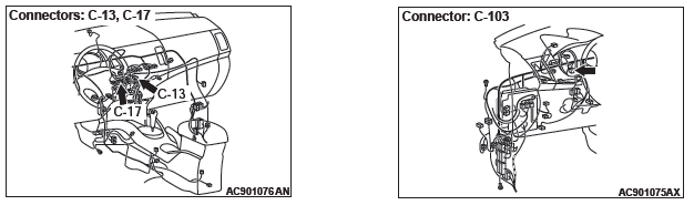
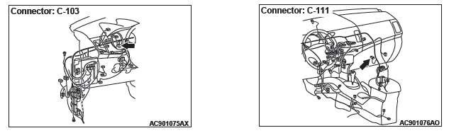
STEP 1. Check joint connector (CAN1) C-103, CAN box unit connector C-13 and intermediate connector C-17 for loose, corroded or damaged terminals, or terminals pushed back in the connector.
CAUTION The strand end of the twisted wire should be within 10 cm (4 inches) from the connector.
Q: Are joint connector (CAN1) C-103, CAN box unit connector C-13 and intermediate connector C-17 in good condition?
YES : Go to Step 2.
NO : Repair the damaged parts.
STEP 2. Check the wiring harness between joint connector (CAN1) C-103 and CAN box unit connector C-13 for open circuit.
CAUTION Strictly observe the specified wiring harness repair procedure.
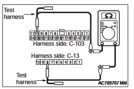
(1) Disconnect joint connector (CAN1) C-103 and CAN box unit connector C-13, and check the wiring harness.
(2) Check the wiring harness between joint connector (CAN1) C-103 (terminal No.10) and CAN box unit connector C-13 (terminal No.8)
OK: Continuity exists (2 ohms or less)
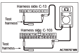
(3) Check the wiring harness between joint connector (CAN1) C-103 (terminal No.23) and CAN box unit connector C-13 (terminal No.9)
OK: Continuity exists (2 ohms or less)
Q: Is the wiring harness between joint connector (CAN1) C-103 and CAN box unit connector C-13 in good condition?
YES : Check the power supply circuit of the CAN box unit.
NO : Repair the wiring harness between joint connector (CAN1) C-103 and CAN box unit connector C-13.
DIAGNOSTIC ITEM 23: Diagnose when the scan tool cannot receive the data sent by satellite radio tuner <vehicles with satellite radio>.
CAUTION When servicing a CAN bus line, ground yourself by touching a metal object such as an unpainted water pipe. If you fail to do so, a component connected to the CAN bus line may be damaged.
CAN Communication Circuit
FUNCTION
If the scan tool MB991958 cannot communicate with the satellite radio tuner, this diagnosis result will be set.
TROUBLE JUDGMENT CONDITIONS
If a communication flag is not set for the satellite radio tuner, the ETACS-ECU determines that there is a failure.
TROUBLESHOOTING HINTS
- Malfunction of the connector [joint connector (CAN1), satellite radio tuner connector improperly connected]
- Malfunction of the wiring harness [open circuit between the satellite radio tuner connector and the joint connector (CAN1), power supply circuit to the satellite radio tuner]
- Malfunction of the satellite radio tuner
DIAGNOSIS
Required Special Tools:
- MB991223: Harness Set
- MB992006: Extra Fine Probe
STEP 1. Check joint connector (CAN1) C-103 and satellite radio tuner connector C-111 for loose, corroded or damaged terminals, or terminals pushed back in the connector.
CAUTION The strand end of the twisted wire should be within 10 cm (4 inches) from the connector.
Q: Are joint connector (CAN1) C-103 and satellite radio tuner connector C-111 in good condition?
YES : Go to Step 2.
NO : Repair the damaged parts.
STEP 2. Check the wiring harness between joint connector (CAN1) C-103 and satellite radio tuner connector C-111 for open circuit.
CAUTION Strictly observe the specified wiring harness repair procedure.
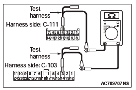
(1) Disconnect joint connector (CAN1) C-103 and satellite radio tuner connector C-111, and check the wiring harness.
(2) Check the wiring harness between joint connector (CAN1) C-103 (terminal No.3) and satellite radio tuner connector C-111 (terminal No.4)
OK: Continuity exists (2 ohms or less)
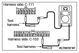
(3) Check the wiring harness between joint connector (CAN1) C-103 (terminal No.14) and satellite radio tuner connector C-111 (terminal No.11)
OK: Continuity exists (2 ohms or less)
Q: Is the wiring harness between joint connector (CAN1) C-103 and satellite radio tuner connector C-111 in good condition?
YES : Check the power supply circuit of the satellite radio tuner. NO : Repair the wiring harness between joint connector (CAN1) C-103 and satellite radio tuner connector C-111.
READ NEXT:
 Diagnostic Item 24-25
DIAGNOSTIC ITEM 24: Short to power supply or ground in both CAN_H and
CAN_L lines of the
CAN-B bus lines.
CAUTION
When servicing a CAN bus line, ground yourself
by touching a metal object such as an
Diagnostic Item 26
DIAGNOSTIC ITEM 26: Short to power supply or ground, open circuit or
line-to-line short in the
CAN-B bus lines.
CAUTION
When servicing a CAN bus line, ground yourself by touching a metal object such
SEE MORE:
Rear Wiper and Washer
REMOVAL AND INSTALLATION
Washer tank
Washer motor
Rear washer nozzle removal
steps
Liftgate spoiler
High-mounted stop light assembly
Rear washer nozzle assembly
Rear wiper blade removal steps
Rear wiper blade assembly
Rear wiper blade
Rear wiper motor removal steps
Cover
Rear wip
Forward Clutch
DISASSEMBLY AND ASSEMBLY
Disassembly steps
Snap ring
Internal gear
Snap ring
Snap ring
Seal ring (small)
Seal ring (big)
Input shaft
Forward clutch sub-assembly
DISASSEMBLY SERVICE POINT
SNAP RING REMOVAL
Using a flat blade screwdriver etc., remove the snap ring from
the forward clutch dr
