Mitsubishi Outlander: Diagnostic Item 6-13
DIAGNOSTIC ITEM 6: Diagnose when the scan tool cannot receive the data sent by AWD-ECU <Electronic controlled AWD>.
CAUTION When servicing a CAN bus line, ground yourself by touching a metal object such as an unpainted water pipe. If you fail to do so, a component connected to the CAN bus line may be damaged.
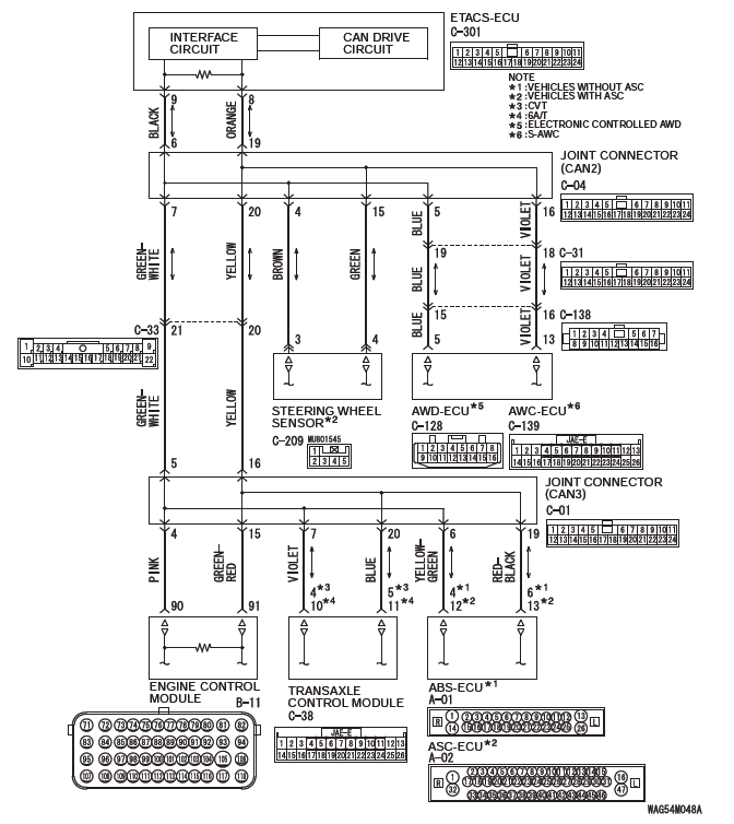
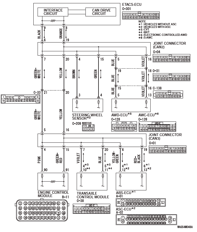
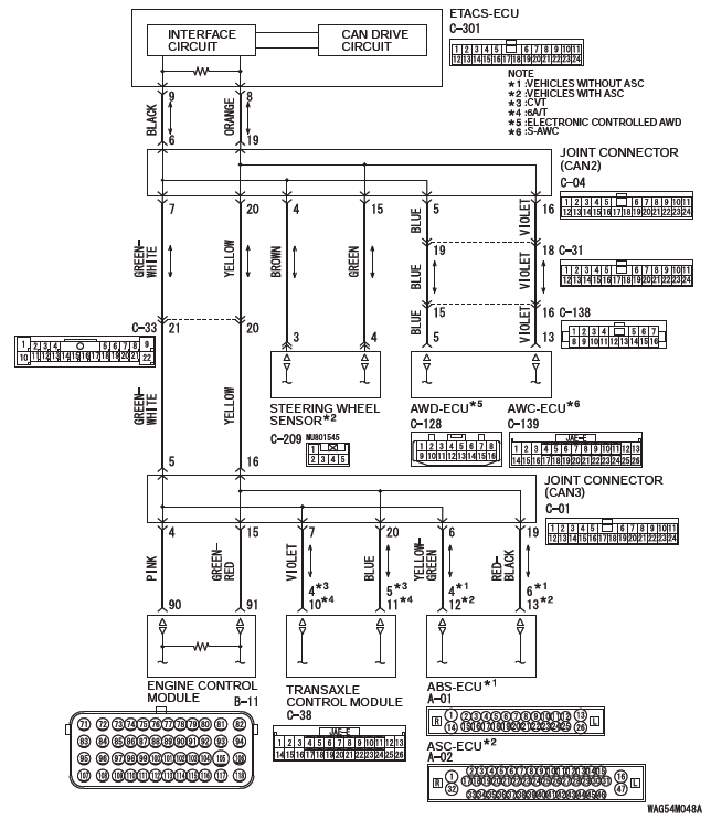
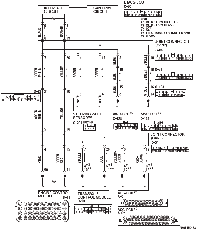
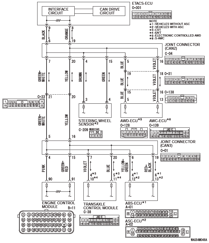
CAN Communication Circuit
FUNCTION
If the scan tool MB991958 cannot communicate with the AWD-ECU, this diagnosis result will be set.
TROUBLE JUDGMENT CONDITIONS
If a communication flag is not set for the AWD-ECU, the ETACS-ECU determines that there is a failure.
TROUBLESHOOTING HINTS
- Malfunction of the connector [joint connector (CAN2) or AWD-ECU connector improperly connected]
- Malfunction of the wiring harness [open circuit between the AWD-ECU and the joint connector (CAN2), power supply circuit to the AWD-ECU]
- Malfunction of the AWD-ECU
DIAGNOSIS
Required Special Tools:
- MB991223: Harness Set
- MB992006: Extra Fine Probe
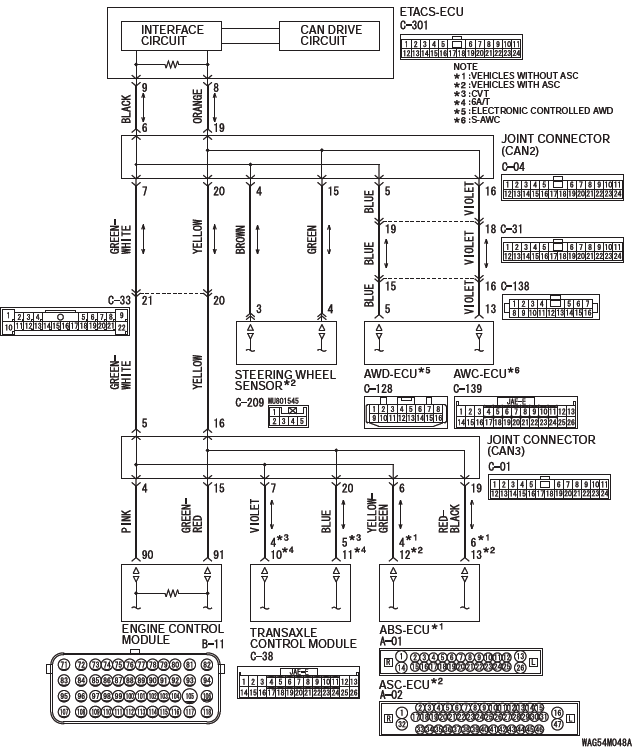
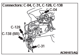
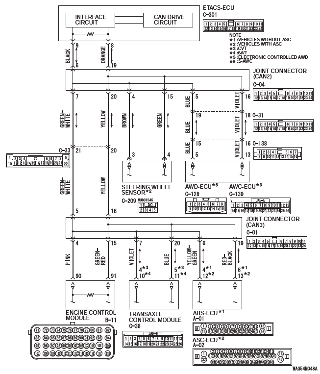
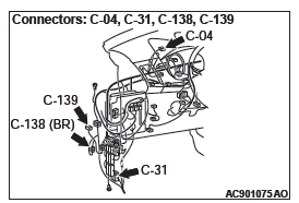
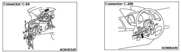
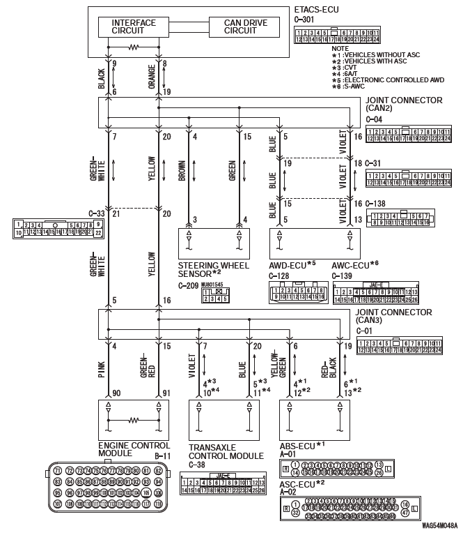
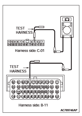
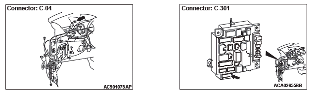
STEP 1. Check joint connector (CAN2) C-04, AWD-ECU connector C-128, intermediate connector C-138 and intermediate connector C-31 for loose, corroded or damaged terminals, or terminals pushed back in the connector.
CAUTION The strand end of the twisted wire should be within 10 cm (4 inches) from the connector.
Q: Are joint connector (CAN2) C-04, AWD-ECU connector C-128, intermediate connector C-138 and intermediate connector C-31 in good condition?
YES : Go to Step 2.
NO : Repair the damaged parts.
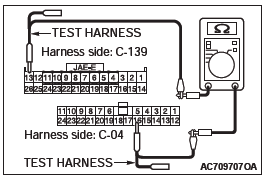
STEP 2. Check the wiring harness between joint connector (CAN2) C-04 and AWD-ECU connector C-128 for open circuit.
CAUTION Strictly observe the specified wiring harness repair procedure.
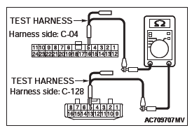
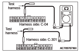
(1) Disconnect joint connector (CAN2) C-04 and AWD-ECU connector C-301, and check the wiring harness.
(2) Check the wiring harness between joint connector (CAN2) C-04 (terminal No.5) and AWD-ECU connector C-128 (terminal No.5)
OK: Continuity exists (2 ohms or less)
(3) Check the wiring harness between joint connector (CAN2) C-04 (terminal No.16) and AWD-ECU connector C-128 (terminal No.13)
OK: Continuity exists (2 ohms or less)
Q: Is the wiring harness between joint connector (CAN2) C-04 and AWD-ECU connector C-128 in good condition?
YES : Check the power supply circuit of the AWD-ECU.
NO : Repair the wiring harness between joint connector (CAN2) C-04 and AWD-ECU connector C-128.
DIAGNOSTIC ITEM 7: Diagnose when the scan tool cannot receive the data sent by AWC-ECU <S-AWC>.
CAUTION When servicing a CAN bus line, ground yourself by touching a metal object such as an unpainted water pipe. If you fail to do so, a component connected to the CAN bus line may be damaged.
CAN Communication Circuit
FUNCTION
If the scan tool MB991958 cannot communicate with the AWC-ECU, this diagnosis result will be set.
TROUBLE JUDGMENT CONDITIONS
If a communication flag is not set for the AWC-ECU, the ETACS-ECU determines that there is a failure.
TROUBLESHOOTING HINTS
- Malfunction of the connector [joint connector (CAN2) or AWC-ECU connector improperly connected]
- Malfunction of the wiring harness [open circuit between the AWC-ECU and the joint connector (CAN2), power supply circuit to the AWC-ECU]
- Malfunction of the AWC-ECU
DIAGNOSIS
Required Special Tools:
- MB991223: Harness Set
- MB992006: Extra Fine Probe
STEP 1. Check joint connector (CAN2) C-04, AWC-ECU connector C-139, intermediate connector C-138 and intermediate connector C-31 for loose, corroded or damaged terminals, or terminals pushed back in the connector.
CAUTION The strand end of the twisted wire should be within 10 cm (4 inches) from the connector.
Q: Are joint connector (CAN2) C-04, AWC-ECU connector C-139, intermediate connector C-138 and intermediate connector C-31 in good condition?
YES : Go to Step 2.
NO : Repair the damaged parts.
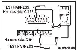
STEP 2. Check the wiring harness between joint connector (CAN2) C-04 and AWC-ECU connector C-139 for open circuit.
CAUTION Strictly observe the specified wiring harness repair procedure.
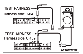
(1) Disconnect joint connector (CAN2) C-04 and AWC-ECU connector C-301, and check the wiring harness.
(2) Check the wiring harness between joint connector (CAN2) C-04 (terminal No.5) and AWC-ECU connector C-139 (terminal No.5)
OK: Continuity exists (2 ohms or less)
(3) Check the wiring harness between joint connector (CAN2) C-04 (terminal No.16) and AWC-ECU connector C-139 (terminal No.13)
OK: Continuity exists (2 ohms or less)
Q: Is the wiring harness between joint connector (CAN2) C-04 and AWC-ECU connector C-139 in good condition?
YES : Check the power supply circuit of the AWC-ECU.
NO : Repair the wiring harness between joint connector (CAN2) C-04 and AWC-ECU connector C-139.
DIAGNOSTIC ITEM 8: Diagnose when the scan tool cannot receive the data sent by steering wheel sensor <Vehicles with ASC>.
CAUTION When servicing a CAN bus line, ground yourself by touching a metal object such as an unpainted water pipe. If you fail to do so, a component connected to the CAN bus line may be damaged.
CAN Communication Circuit
FUNCTION
If the scan tool MB991958 cannot communicate with the steering wheel sensor, this diagnosis result will be set.
TROUBLE JUDGMENT CONDITIONS
If a communication flag is not set for the steering wheel sensor, the ETACS-ECU determines that there is a failure.
TROUBLESHOOTING HINTS
- Malfunction of the connector [joint connector (CAN2) or steering wheel sensor connector improperly connected]
- Malfunction of the wiring harness [open circuit between the steering wheel sensor and the joint connector (CAN2), power supply circuit to the steering wheel sensor]
- Malfunction of the steering wheel sensor
DIAGNOSIS
Required Special Tools:
- MB991223: Harness Set
- MB992006: Extra Fine Probe
STEP 1. Check joint connector (CAN2) C-04 and steering wheel sensor connector C-209 for loose, corroded or damaged terminals, or terminals pushed back in the connector.
CAUTION The strand end of the twisted wire should be within 10 cm (4 inches) from the connector.
Q: Are joint connector (CAN2) C-04 and steering wheel sensor connector C-209 in good condition?
YES : Go to Step 2.
NO : Repair the damaged parts.
STEP 2. Check the wiring harness between joint connector (CAN2) C-04 and steering wheel sensor connector C-209 for open circuit.
CAUTION Strictly observe the specified wiring harness repair procedure.
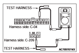
(1) Disconnect joint connector (CAN2) C-04 and steering wheel sensor connector C-209, and check the wiring harness.
(2) Check the wiring harness between joint connector (CAN2) C-04 (terminal No.4) and steering wheel sensor connector C-209 (terminal No.3)
OK: Continuity exists (2 ohms or less)
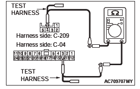
(3) Check the wiring harness between joint connector (CAN2) C-04 (terminal No.15) and steering wheel sensor connector C-209 (terminal No.4)
OK: Continuity exists (2 ohms or less)
Q: Is the wiring harness between joint connector (CAN2) C-04 and steering wheel sensor connector C-209 in good condition?
YES : Check the power supply circuit of the steering wheel sensor. NO : Repair the wiring harness between joint connector (CAN2) C-04 and steering wheel sensor connector C-209.
DIAGNOSTIC ITEM 9: Diagnose when the scan tool cannot receive the data sent by TCM <CVT, A/T>.
CAUTION When servicing a CAN bus line, ground yourself by touching a metal object such as an unpainted water pipe. If you fail to do so, a component connected to the CAN bus line may be damaged.
CAN Communication Circuit
FUNCTION
If the scan tool MB991958 cannot communicate with the TCM, this diagnosis result will be set.
TROUBLE JUDGMENT CONDITIONS
If a communication flag is not set for the TCM, the ETACS-ECU determines that there is a failure.
TROUBLESHOOTING HINTS
- Malfunction of the connector [joint connector (CAN3) or TCM connector improperly connected]
- Malfunction of the wiring harness [open circuit between the TCM and the joint connector (CAN3), power supply circuit to the TCM]
- Malfunction of the TCM
DIAGNOSIS
Required Special Tools:
- MB991223: Harness Set
- MB992006: Extra Fine Probe
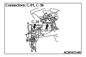
STEP 1. Check joint connector (CAN3) C-01 and TCM connector C-38 for loose, corroded or damaged terminals, or terminals pushed back in the connector.
CAUTION The strand end of the twisted wire should be within 10 cm (4 inches) from the connector.
Q: Are joint connector (CAN3) C-01 and TCM connector C-38 in good condition?
YES : Go to Step 2.
NO : Repair the damaged parts.
STEP 2. Check the wiring harness between joint connector (CAN3) C-01 and TCM connector C-38 for open circuit.
CAUTION Strictly observe the specified wiring harness repair procedure.
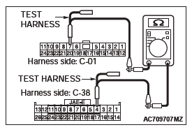
(1) Disconnect joint connector (CAN3) C-01 and TCM connector C-38, and check the wiring harness.
(2) Check the wiring harness between joint connector (CAN3) C-01 (terminal No.7) and TCM connector C-38 (terminal No.4) <CVT>
OK: Continuity exists (2 ohms or less)
(3) Check the wiring harness between joint connector (CAN3) C-01 (terminal No.20) and TCM connector C-38 (terminal No.5) <CVT>
OK: Continuity exists (2 ohms or less)
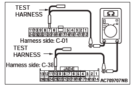
(4) Check the wiring harness between joint connector (CAN3) C-01 (terminal No.7) and TCM connector C-38 (terminal No.10) <A/T>
OK: Continuity exists (2 ohms or less)
(5) Check the wiring harness between joint connector (CAN3) C-01 (terminal No.20) and TCM connector C-38 (terminal No.11) <A/T>
OK: Continuity exists (2 ohms or less)
Q: Is the wiring harness between joint connector (CAN3) C-01 and TCM connector C-38 in good condition?
YES : Check the power supply circuit of the TCM.
NO : Repair the wiring harness between joint connector (CAN3) C-01 and TCM connector C-38.
DIAGNOSTIC ITEM 10: Diagnose when the scan tool cannot receive the data sent by ABS-ECU <vehicles without ASC>.
CAUTION When servicing a CAN bus line, ground yourself by touching a metal object such as an unpainted water pipe. If you fail to do so, a component connected to the CAN bus line may be damaged.
CAN Communication Circuit
FUNCTION
If the scan tool MB991958 cannot communicate with the ABS-ECU, this diagnosis result will be set.
TROUBLE JUDGMENT CONDITIONS
If a communication flag is not set for the ABS-ECU, the ETACS-ECU determines that there is a failure.
TROUBLESHOOTING HINTS
- Malfunction of the connector [joint connector (CAN3) or ABS-ECU connector improperly connected]
- Malfunction of the wiring harness [open circuit between the ABS-ECU and the joint connector (CAN3), power supply circuit to the ABS-ECU]
- Malfunction of the ABS-ECU
DIAGNOSIS
Required Special Tools:
- MB991223: Harness Set
- MB992006: Extra Fine Probe
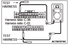
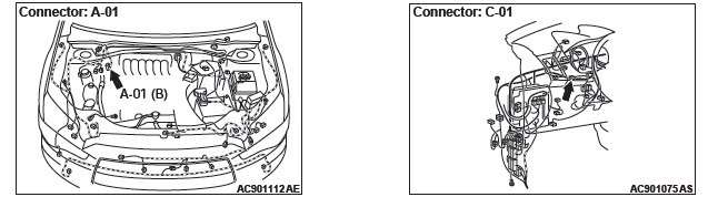
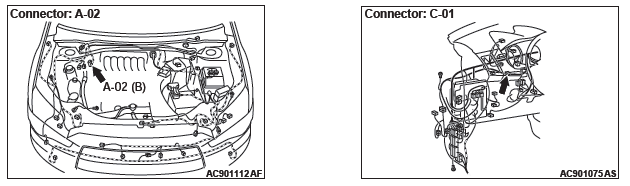
STEP 1. Check joint connector (CAN3) C-01 and ABS-ECU connector A-01 for loose, corroded or damaged terminals, or terminals pushed back in the connector.
CAUTION The strand end of the twisted wire should be within 10 cm (4 inches) from the connector.
Q: Are joint connector (CAN3) C-01 and ABS-ECU connector A-01 in good condition?
YES : Go to Step 2.
NO : Repair the damaged parts.
STEP 2. Check the wiring harness between joint connector (CAN3) C-01 and ABS-ECU connector A-01 for open circuit.
CAUTION Strictly observe the specified wiring harness repair procedure.
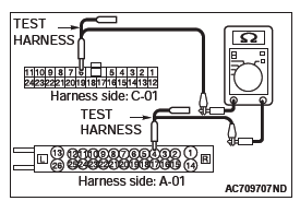
(1) Disconnect joint connector (CAN3) C-01 and ABS-ECU connector A-01, and check the wiring harness.
(2) Check the wiring harness between joint connector (CAN3) C-01 (terminal No.6) and ABS-ECU connector A-01 (terminal No.4)
OK: Continuity exists (2 ohms or less)
(3) Check the wiring harness between joint connector (CAN3) C-01 (terminal No.19) and ABS-ECU connector A-01 (terminal No.6)
OK: Continuity exists (2 ohms or less)
Q: Is the wiring harness between joint connector (CAN3) C-01 and ABS-ECU connector A-01 in good condition?
YES : Check the power supply circuit of the ABS-ECU.
NO : Repair the wiring harness between joint connector (CAN3) C-01 and ABS-ECU connector A-01.
DIAGNOSTIC ITEM 11: Diagnose when the scan tool cannot receive the data sent by ASC-ECU <vehicles with ASC>.
CAUTION When servicing a CAN bus line, ground yourself by touching a metal object such as an unpainted water pipe. If you fail to do so, a component connected to the CAN bus line may be damaged.
CAN Communication Circuit
FUNCTION
If the scan tool MB991958 cannot communicate with the ASC-ECU, this diagnosis result will be set.
TROUBLE JUDGMENT CONDITIONS
If a communication flag is not set for the ASC-ECU, the ETACS-ECU determines that there is a failure.
TROUBLESHOOTING HINTS
- Malfunction of the connector [joint connector (CAN3) or ASC-ECU connector improperly connected]
- Malfunction of the wiring harness [open circuit between the ASC-ECU and the joint connector (CAN3), power supply circuit to the ASC-ECU]
- Malfunction of the ASC-ECU
DIAGNOSIS
Required Special Tools:
- MB991223: Harness Set
- MB992006: Extra Fine Probe
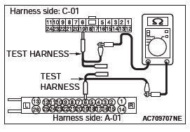
STEP 1. Check joint connector (CAN3) C-01 and ASC-ECU connector A-02 for loose, corroded or damaged terminals, or terminals pushed back in the connector.
CAUTION The strand end of the twisted wire should be within 10 cm (4 inches) from the connector.
Q: Are joint connector (CAN3) C-01 and ASC-ECU connector A-02 in good condition?
YES : Go to Step 2.
NO : Repair the damaged parts.
STEP 2. Check the wiring harness between joint connector (CAN3) C-01 and ASC-ECU connector A-02 for open circuit.
CAUTION Strictly observe the specified wiring harness repair procedure.
(1) Disconnect joint connector (CAN3) C-01 and ASC-ECU connector A-02, and check the wiring harness.
(2) Check the wiring harness between joint connector (CAN3) C-01 (terminal No.6) and ASC-ECU connector A-02 (terminal No.12)
OK: Continuity exists (2 ohms or less)
(3) Check the wiring harness between joint connector (CAN3) C-01 (terminal No.19) and ASC-ECU connector A-02 (terminal No.13)
OK: Continuity exists (2 ohms or less)
Q: Is the wiring harness between joint connector (CAN3) C-01 and ASC-ECU connector A-02 in good condition?
YES : Check the power supply circuit of the ASC-ECU.
NO : Repair the wiring harness between joint connector (CAN3) C-01 and ASC-ECU connector A-02.
DIAGNOSTIC ITEM 12: Diagnose when the scan tool cannot receive the data sent by ECM.
CAUTION When servicing a CAN bus line, ground yourself by touching a metal object such as an unpainted water pipe. If you fail to do so, a component connected to the CAN bus line may be damaged.
CAN Communication Circuit
FUNCTION
If the scan tool MB991958 cannot communicate with the ECM, this diagnosis result will be set.
TROUBLE JUDGMENT CONDITIONS
If a communication flag is not set for the ECM, the ETACS-ECU determines that there is a failure.
TROUBLESHOOTING HINTS
- Malfunction of the connector [joint connector (CAN3) or ECM connector improperly connected]
- Malfunction of the wiring harness [open circuit between the ECM and the joint connector (CAN3), power supply circuit to the ECM]
- Malfunction of the ECM
DIAGNOSIS
Required Special Tools:
- MB991223: Harness Set
- MB992006: Extra Fine Probe
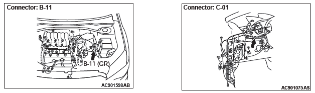
STEP 1. Check joint connector (CAN3) C-01 and ECM connector B-11 for loose, corroded or damaged terminals, or terminals pushed back in the connector.
CAUTION The strand end of the twisted wire should be within 10 cm (4 inches) from the connector.
Q: Are joint connector (CAN3) C-01 and ECM connector B-11 in good condition?
YES : Go to Step 2.
NO : Repair the damaged parts.
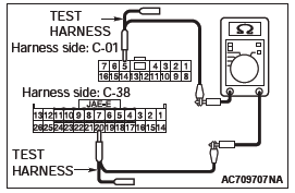
STEP 2. Check the wiring harness between joint connector (CAN3) C-01 and ECM connector B-11 for open circuit.
CAUTION Strictly observe the specified wiring harness repair procedure.
(1) Disconnect joint connector (CAN3) C-01 and ECM connector B-11, and check the wiring harness.
(2) Check the wiring harness between joint connector (CAN3) C-01 (terminal No.4) and ECM connector B-11 (terminal No.90)
OK: Continuity exists (2 ohms or less)
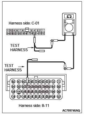
(3) Check the wiring harness between joint connector (CAN3) C-01 (terminal No.15) and ECM connector B-11 (terminal No.91)
OK: Continuity exists (2 ohms or less)
Q: Is the wiring harness between joint connector (CAN3) C-01 and ECM connector B-11 in good condition?
YES : Check the power supply circuit of the ECM.
NO : Repair the wiring harness between joint connector (CAN3) C-01 and ECM connector B-11.
DIAGNOSTIC ITEM 13: Diagnose the lines between the ETACS-ECU and joint connector (CAN2).
CAUTION When servicing a CAN bus line, ground yourself by touching a metal object such as an unpainted water pipe. If you fail to do so, a component connected to the CAN bus line may be damaged.
CAN Communication Circuit
FUNCTION
If a failure is present in the wiring harness between the ETACS-ECU connector and the joint connector (CAN2), this diagnosis result will be set.
TROUBLE JUDGMENT CONDITIONS
If a communication flag is not set for some of the ECUs on the CAN-C line, the ETACS-ECU determines that there is a failure.
TROUBLESHOOTING HINTS
- Malfunction of the connector [joint connector (CAN2) or ETACS-ECU connector improperly connected]
- Malfunction of the wiring harness [open circuit between the ETACS-ECU connector and the joint connector (CAN2), power supply circuit to the engine control module]
- Malfunction of the ETACS-ECU
DIAGNOSIS
Required Special Tools:
- MB991223: Harness Set
- MB992006: Extra Fine Probe
STEP 1. Check joint connector (CAN2) C-04 and ETACS-ECU connector C-301 for loose, corroded or damaged terminals, or terminals pushed back in the connector.
CAUTION The strand end of the twisted wire should be within 10 cm (4 inches) from the connector.
Q: Are joint connector (CAN2) C-04 and ETACS-ECU connector C-301 in good condition?
YES : Go to Step 2.
NO : Repair the damaged parts.
STEP 2. Check the wiring harness between joint connector (CAN2) C-04 and ETACS-ECU connector C-301 for open circuit.
CAUTION Strictly observe the specified wiring harness repair procedure.
(1) Disconnect joint connector (CAN2) C-04 and ETACS-ECU connector C-301, and check the wiring harness.
(2) Check the wiring harness between joint connector (CAN2) C-04 (terminal No.6) and ETACS-ECU connector C-301 (terminal No.9)
OK: Continuity exists (2 ohms or less)
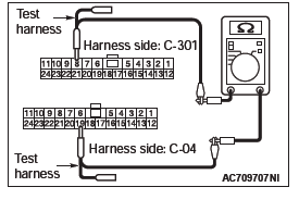
(3) Check the wiring harness between joint connector (CAN2) C-04 (terminal No.19) and ETACS-ECU connector C-301 (terminal No.8)
OK: Continuity exists (2 ohms or less)
Q: Is the wiring harness between joint connector (CAN2) C-04 and ETACS-ECU connector C-301 in good condition?
YES : Go to Step 3.
NO : Repair the wiring harness between joint connector (CAN2) C-04 and ETACS-ECU connector C-301.
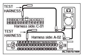
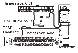
STEP 3. Using scan tool MB991958, diagnose the CAN bus line.
CAUTION To prevent damage to scan tool MB991958, always turn the ignition switch to the "LOCK" (OFF) position before connecting or disconnecting scan tool MB991958.
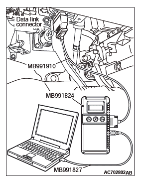
(1) Connect scan tool MB991958 to the data link connector.
(2) Turn the ignition switch to the "ON" position.
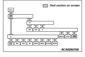
(3) Diagnose CAN bus lines, and check if the scan tool screen is as shown in the illustration.
Q: Does the scan tool screen correspond to the illustration?
YES : The trouble can be an intermittent malfunction.
NO : Replace the ETACS-ECU.
READ NEXT:
 Diagnostic Item 14-23
DIAGNOSTIC ITEM 14: Diagnose the lines between joint connector (CAN2)
and joint connector
(CAN3).
CAUTION
When servicing a CAN bus line, ground yourself by touching a metal object such
as an unpain
Diagnostic Item 24-25
DIAGNOSTIC ITEM 24: Short to power supply or ground in both CAN_H and
CAN_L lines of the
CAN-B bus lines.
CAUTION
When servicing a CAN bus line, ground yourself
by touching a metal object such as an
Diagnostic Item 26
DIAGNOSTIC ITEM 26: Short to power supply or ground, open circuit or
line-to-line short in the
CAN-B bus lines.
CAUTION
When servicing a CAN bus line, ground yourself by touching a metal object such
SEE MORE:
General Information
NOTE: In this manual, F.A.S.T.-key (Free-hand
Advanced Security Transmitter) is described as Keyless
Operation System (KOS).
The keyless operation system (KOS) enables the
driver to unlock all the doors and the liftgate by just
pulling the front door outside handle or operating the
liftgate lock rel
How To Use This Manual
MAINTENANCE, REPAIR AND
SERVICING EXPLANATIONS
This manual provides explanations, etc. concerning
procedures for the inspection, maintenance, repair
and servicing of the subject model. Unless otherwise
specified, each service procedure covers all models.
Procedures covering specific models are iden
