Mitsubishi Outlander: DTC C2104, C1073, C2116, C121D, C121E, C1000
DTC C2104: Faulty valve power supply circuit
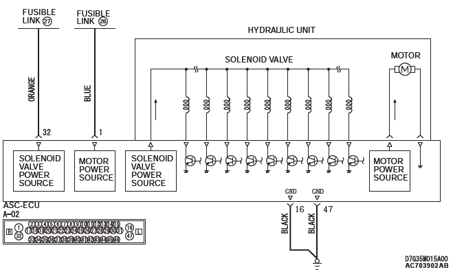
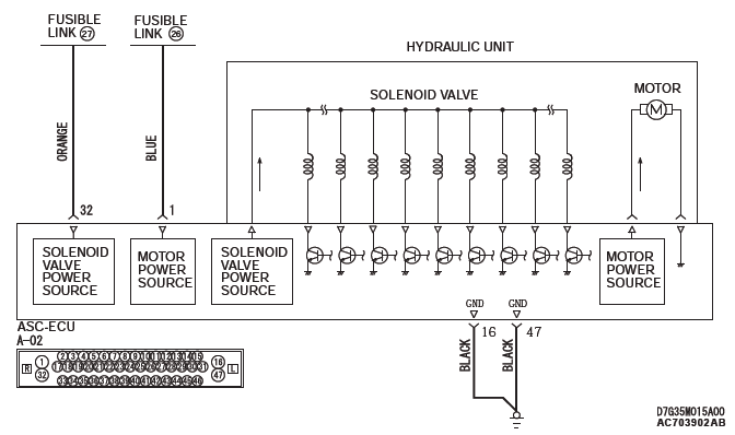
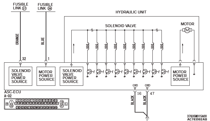
Solenoid Valve and Motor Power Supply Circuit
CAUTION
- If there is any problem in the CAN bus lines, an incorrect diagnostic trouble code may be set. Prior to this diagnosis, diagnose the CAN bus lines (Refer to GROUP 54C − CAN Bus Line Diagnostic Flow).
- Whenever ECU is replaced, ensure that the CAN bus lines are normal.
- When the hydraulic unit (integrated with ASC-ECU) is replaced, always carry out the calibration of the steering wheel sensor, the G and yaw rate sensor and brake fluid pressure sensor.
OPERATION
- ASC-ECU contains the power supply circuit (terminal No.32) for the solenoid valve. The solenoid valve is energized by the valve relay, which is incorporated in ASC-ECU.
- The valve relay, which is incorporated in ASC-ECU, is always energizing the solenoid valve unless the initial check is in progress when the ignition switch is turned on, or the recurrent system check is in progress.
DTC SET CONDITIONS
This diagnostic trouble codes will be set when the solenoid valve supply voltage is not within the standard value.
PROBABLE CAUSES
Current trouble
- Fusible link malfunction
- Damaged wiring harness and connectors
- Abnormality in battery or generator
- ASC-ECU malfunction
Past trouble
- Carry out diagnosis with particular emphasis on wiring harness and connector failures between the power supply circuit (terminal No.32) to ASC-ECU solenoid valve or ground circuit (terminal No.16 and 47). For diagnosis procedures, refer to How to treat past trouble (Refer to GROUP 00 − How to Use Troubleshooting/How to Treat Past Trouble).
DIAGNOSIS
Required Special Tools:
- MB991958: Scan Tool (M.U.T.-III Sub Assembly)
- MB991824: Vehicle Communication Interface (V.C.I.)
- MB991827: M.U.T.-III USB Cable
- MB991910: M.U.T.-III Main Harness A
- MB991997: ASC check harness
STEP 1. Using scan tool MB991958, diagnose the CAN bus lines.
Use scan tool to diagnose the CAN bus lines.
Q: Is the check result normal?
YES : Go to Step 3.
NO : Repair the CAN bus lines (Refer to GROUP 54C − CAN Bus Diagnostics Table). On completion, go to Step 2.
STEP 2. DTC recheck after resetting CAN bus lines
Q: Is DTC C2104 set?
YES : Go to Step 3.
NO : The procedure is complete.
STEP 3. Battery check
Q: Is the battery in good condition?
YES : Go to Step 5.
NO : Replace the battery. Then go to Step 4.
STEP 4. Charging system check
Q: Is the charging system in good condition?
YES : Go to Step 5.
NO : Repair or replace the charging system component(s).
Then go to Step 11.
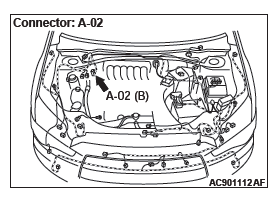
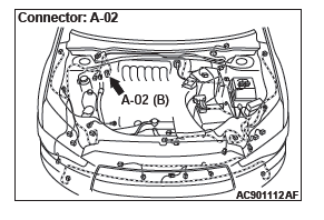
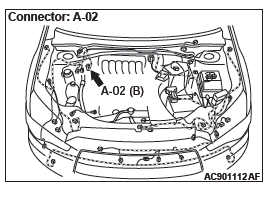
STEP 5. Connector check: A-02 ASC-ECU connector
Q: Is the check result normal?
YES : Go to Step 6.
NO : Repair the defective connector. Then go to Step 11.
STEP 6. Fusible link check: Check the fusible link No.27.
Visually check for open circuit in the fusible link No.27.
Q: Is the check result normal?
YES : Go to Step 8.
NO : Go to Step 7.
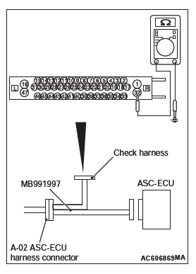
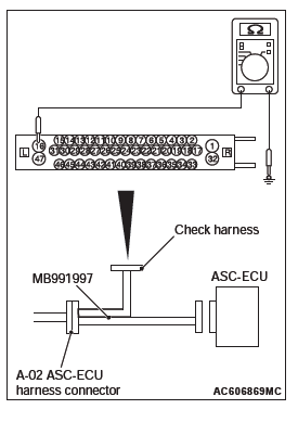
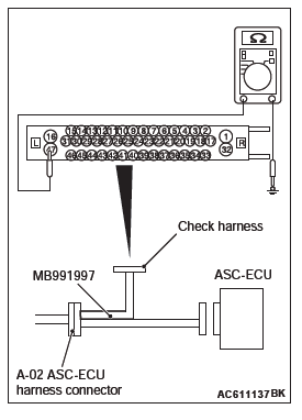
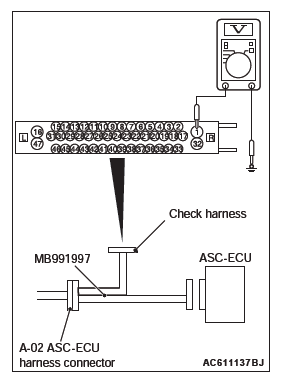
STEP 7. Resistance measurement at A-02 ASC-ECU connector
- Disconnect the ASC-ECU connector, connect special tool
ASC check harness (MB991997) to the harness-side
connector, and then measure the resistance at the special
tool connector side.
NOTE: Do not connect the special tool ASC check harness (MB991997) to ASC-ECU.
- Disconnect the fusible link No.27.
- Measure the resistance between the terminal No.32 and the
body ground.
OK: No continuity
Q: Is the check result normal?
YES : Replace the fusible link No.27. Then go to Step 11.
NO : The short circuit may be present in the power supply circuit. Repair the wiring harness between the A-02 ASC-ECU connector terminal No.32 and the fusible link No.27, and then replace the fusible link No.27.
Then go to Step 11.
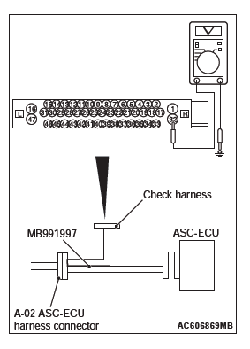
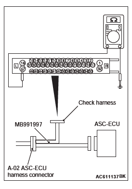
STEP 8. Voltage measurement at the A-02 ASC-ECU connector
- Disconnect the ASC-ECU connector, connect special tool
ASC check harness (MB991997) to the harness-side
connector, and then measure the voltage at the special tool
connector side.
NOTE: Do not connect the special tool ASC check harness (MB991997) to ASC-ECU.
- Measure the voltage between the terminal No.32 and the
body ground.
OK: Approximately system voltage
Q: Is the check result normal?
YES : Go to Step 9.
NO : The open circuit may be present in the power supply circuit. Repair the wiring harness between the A-02 ASC-ECU connector terminal No.32 and the fusible link No.27. Then go to Step 11.
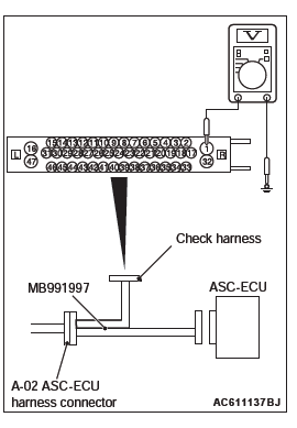
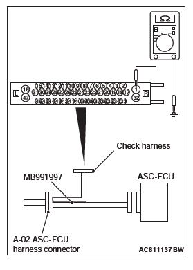
STEP 9. Resistance measurement at A-02 ASC-ECU connector
- Disconnect the ASC-ECU connector, connect special tool
ASC check harness (MB991997) to the harness-side
connector, and then measure the resistance at the special
tool connector side.
NOTE: Do not connect the special tool ASC check harness (MB991997) to ASC-ECU.
- Measure the resistance between the terminal No.16 and the
body ground, and between the terminal No.47 and the body
ground.
OK: Continuity exists (2 Ω or less)
Q: Is the check result normal?
YES : Go to Step 10.
NO : An open circuit may be present in the ground circuit.
Repair the wiring harness between the A-02 ASC-ECU connector terminal No.16 and the body ground, and between the A-02 ASC-ECU connector terminal No.47 and the body ground. Then go to Step 11.
STEP 10. Check whether the DTC is reset.
Erase the DTC.
Q: Is DTC C2104 set?
YES : Replace the hydraulic unit (integrated with ASC-ECU). Then go to Step 11.
NO : Intermittent malfunction (Refer to GROUP 00 − How to Use Troubleshooting/How to Cope with Intermittent Malfunctions).
STEP 11. Check whether the DTC is reset.
Erase the DTC.
Q: Is DTC C2104 set?
YES : Return to Step 1.
NO : The procedure is complete.
DTC C1073: Faulty motor drive circuit
Solenoid Valve and Motor Power Supply Circuit
CAUTION
- If there is any problem in the CAN bus lines, an incorrect diagnostic trouble code may be set. Prior to this diagnosis, diagnose the CAN bus lines (Refer to GROUP 54C − CAN Bus Line Diagnostic Flow).
- Whenever ECU is replaced, ensure that the CAN bus lines are normal.
- When the hydraulic unit (integrated with ASC-ECU) is replaced, always carry out the calibration of the steering wheel sensor, the G and yaw rate sensor and brake fluid pressure sensor.
OPERATION
- ASC-ECU contains the power supply circuit (terminal No. 1) for the pump motor. The pump motor is energized by the motor switch, which is incorporated in ASC-ECU.
- The pump motor switch, which is incorporated in ASC-ECU, is always off unless the motor and solenoid valve check is activated when the vehicle is started.
- ASC-ECU activates the pump motor by turning on the ECU built-in pump motor switch.
DTC SET CONDITIONS
If the pump motor switch voltage drop indicates high value when the pump motor operates or after the operation, the pump motor operation is stopped and this diagnostic trouble code is set.
PROBABLE CAUSES
Current trouble
- Fusible link malfunction
- Damaged wiring harness and connectors
- Abnormality in battery or generator
- ASC-ECU malfunction
Past trouble
- Carry out diagnosis with particular emphasis on wiring harness and connector failures between the power supply circuit (A-02 ASC-ECU connector terminal No.1) to the ASC-ECU motor and the ground circuit (A-02 ASC-ECU connector terminal No.47). For diagnosis procedures, refer to How to treat past trouble (Refer to GROUP 00 − How to Use Troubleshooting/How to Treat Past Trouble).
DIAGNOSIS
Required Special Tools:
- MB991958: Scan Tool (M.U.T.-III Sub Assembly)
- MB991824: Vehicle Communication Interface (V.C.I.)
- MB991827: M.U.T.-III USB Cable
- MB991910: M.U.T.-III Main Harness A
- MB991997: ASC check harness
STEP 1. Using scan tool MB991958, diagnose the CAN bus lines.
Use scan tool to diagnose the CAN bus lines.
Q: Is the check result normal?
YES : Go to Step 3.
NO : Repair the CAN bus lines (Refer to GROUP 54C − CAN Bus Diagnostics Table). On completion, go to Step 2.
STEP 2. DTC recheck after resetting CAN bus lines
Q: Is DTC C1073 set?
YES : Go to Step 3.
NO : The procedure is complete.
STEP 3. Battery check
Q: Is the battery in good condition?
YES : Go to Step 5.
NO : Replace the battery. Then go to Step 4.
STEP 4. Charging system check
Q: Is the charging system in good condition?
YES : Go to Step 5.
NO : Repair or replace the charging system component(s).
Then go to Step 11.
STEP 5. Connector check: A-02 ASC-ECU connector
Q: Is the check result normal?
YES : Go to Step 6.
NO : Repair the defective connector. Then go to Step 11.
STEP 6. Fusible link check: Check the fusible link No.26.
Q: Is the check result normal?
YES : Go to Step 8.
NO : Go to Step 7.
STEP 7. Resistance measurement at A-02 ASC-ECU connector
- Disconnect the ASC-ECU connector, connect special tool
ASC check harness (MB991997) to the harness-side
connector, and then measure the resistance at the special
tool connector side.
NOTE: Do not connect the special tool ASC check harness (MB991997) to ASC-ECU.
- Disconnect the fusible link No.26.
- Measure the resistance between the terminal No.1 and the
body ground.
OK: No continuity
Q: Is the check result normal?
YES : Replace the fusible link No.26. Then go to Step 11.
NO : The short circuit may be present in the power supply circuit. Repair the wiring harness between the A-02 ASC-ECU connector terminal No.1 and the fusible link No.26, and then replace the fusible link No.26.
Then go to Step 11.

STEP 8. Voltage measurement at the A-02 ASC-ECU connector
- Disconnect the ASC-ECU connector, connect special tool
ASC check harness (MB991997) to the harness-side
connector, and then measure the voltage at the special tool
connector side.
NOTE: Do not connect the special tool ASC check harness (MB991997) to ASC-ECU.
- Measure the voltage between the terminal No.1 and the
body ground.
OK: Approximately system voltage
Q: Is the check result normal?
YES : Go to Step 9.
NO : The open circuit may be present in the power supply circuit. Repair the wiring harness between the A-02 ASC-ECU connector terminal No.1 and the fusible link No.26. Then go to Step 11.
STEP 9. Resistance measurement at A-02 ASC-ECU connector
- Disconnect the ASC-ECU connector, connect special tool
ASC check harness (MB991997) to the harness-side
connector, and then measure the resistance at the special
tool connector side.
NOTE: Do not connect the special tool ASC check harness (MB991997) to ASC-ECU.
- Measure the resistance between the terminal No.16 and the
body ground, and between the terminal No.47 and the body
ground.
OK: Continuity exists (2 Ω or less)
Q: Is the check result normal?
YES : Go to Step 10.
NO : An open circuit may be present in the ground circuit.
Repair the wiring harness between the A-02 ASC-ECU connector terminal No.16 and the body ground, and between the A-02 ASC-ECU connector terminal No.47 and the body ground. Then go to Step 11.
STEP 10. Check whether the DTC is reset.
- Erase the DTC.
- Drive the vehicle at 12 mph (20 km/h) or higher.
NOTE: The ABS warning light does not turn OFF in some cases unless the vehicle runs at 12 mph (20 km/h) or higher.
Q: Is DTC C1073?
YES : Replace the hydraulic unit (integrated with ASC-ECU). Then go to Step 11.
NO : Intermittent malfunction (Refer to GROUP 00 − How to Use Troubleshooting/How to Cope with Intermittent Malfunctions).
STEP 11. Check whether the DTC is reset.
- Erase the DTC.
- Drive the vehicle at 12 mph (20 km/h) or higher.
NOTE: The ABS warning light does not turn OFF in some cases unless the vehicle runs at 12 mph (20 km/h) or higher.
Q: Is DTC C1073?
YES : Return to Step 1.
NO : The procedure is complete.
DTC C2116: Low or high power supply voltage in pump motor
Solenoid Valve and Motor Power Supply Circuit
CAUTION
- If there is any problem in the CAN bus lines, an incorrect diagnostic trouble code may be set. Prior to this diagnosis, diagnose the CAN bus lines (Refer to GROUP 54C − CAN Bus Line Diagnostic Flow).
- Whenever ECU is replaced, ensure that the CAN bus lines are normal.
- When the hydraulic unit (integrated with ASC-ECU) is replaced, always carry out the calibration of the steering wheel sensor, the G and yaw rate sensor and brake fluid pressure sensor.
CIRCUIT OPERATION
- ASC-ECU contains the power supply circuit (terminal No.1) for the pump motor. The pump motor is energized by the motor switch, which is incorporated in ASC-ECU.
- The pump motor switch, which is incorporated in ASC-ECU, is always off unless the motor and solenoid valve check is activated when the vehicle is started.
- ASC-ECU activates the pump motor by turning on the ECU built-in pump motor switch.
DTC SET CONDITIONS
This diagnostic trouble codes will be set under the cases below:
- When the power supply voltage of the pump motor, which is not in operation, is abnormally low for a prolonged period
- When the power supply voltage of the pump motor, which is not in operation, is abnormally high for a prolonged period
PROBABLE CAUSES
Current trouble
- Fusible link malfunction
- Damaged wiring harness and connectors
- Abnormality in battery or generator
- ASC-ECU malfunction
Past trouble
- Carry out diagnosis with particular emphasis on wiring harness and connector failures between the power supply circuit (A-02 ASC-ECU connector terminal No. 1) to the ASC-ECU motor and the ground circuit (A-02 ASC-ECU connector terminal No.16 and 47). For diagnosis procedures, refer to How to treat past trouble (Refer to GROUP 00 − How to Use Troubleshooting/How to Treat Past Trouble).
DIAGNOSIS
Required Special Tools:
- MB991958: Scan Tool (M.U.T.-III Sub Assembly)
- MB991824: Vehicle Communication Interface (V.C.I.)
- MB991827: M.U.T.-III USB Cable
- MB991910: M.U.T.-III Main Harness A
- MB991997: ASC check harness
STEP 1. Using scan tool MB991958, diagnose the CAN bus lines.
Use scan tool to diagnose the CAN bus lines.
Q: Is the check result normal?
YES : Go to Step 3.
NO : Repair the CAN bus lines (Refer to GROUP 54C − CAN Bus Diagnostics Table). On completion, go to Step 2.
STEP 2. DTC recheck after resetting CAN bus lines
Q: Is DTC C2116 set?
YES : Go to Step 3.
NO : The procedure is complete.
STEP 3. Battery check
Q: Is the battery in good condition?
YES : Go to Step 5.
NO : Replace the battery. Then go to Step 4.
STEP 4. Charging system check
Q: Is the charging system in good condition?
YES : Go to Step 5.
NO : Repair or replace the charging system component(s).
Then go to Step 11.
STEP 5. Connector check: A-02 ASC-ECU connector
Q: Is the check result normal?
YES : Go to Step 6.
NO : Repair the defective connector. Then go to Step 11.
STEP 6. Fusible link check: Check the fusible link No.26.
Visually check for open circuit in the fusible link No.26.
Q: Is the check result normal?
YES : Go to Step 8.
NO : Go to Step 7.
STEP 7. Resistance measurement at A-02 ASC-ECU connector
- Disconnect the ASC-ECU connector, connect special tool
ASC check harness (MB991997) to the harness-side
connector, and then measure the resistance at the special
tool connector side.
NOTE: Do not connect the special tool ASC check harness (MB991997) to ASC-ECU.
- Disconnect the fusible link No.26.
- Measure the resistance between the terminal No.1 and the
body ground.
OK: No continuity
Q: Is the check result normal?
YES : Replace the fusible link No.26. Then go to Step 11.
NO : The short circuit may be present in the power supply circuit. Repair the wiring harness between the A-02 ASC-ECU connector terminal No.1 and the fusible link No.26, and then replace the fusible link No.26.
Then go to Step 11.
STEP 8. Voltage measurement at the A-02 ASC-ECU connector
- Disconnect the ASC-ECU connector, connect special tool
ASC check harness (MB991997) to the harness-side
connector, and then measure the voltage at the special tool
connector side.
NOTE: Do not connect the special tool ASC check harness (MB991997) to ASC-ECU.
- Measure the voltage between the terminal No.1 and the
body ground.
OK: Approximately system voltage
Q: Is the check result normal?
YES : Go to Step 9.
NO : The open circuit may be present in the power supply circuit. Repair the wiring harness between the A-02 ASC-ECU connector terminal No.1 and the fusible link No.26. Then go to Step 11.
STEP 9. Resistance measurement at A-02 ASC-ECU connector
- Disconnect the ASC-ECU connector, connect special tool
ASC check harness (MB991997) to the harness-side
connector, and then measure the resistance at the special
tool connector side.
NOTE: Do not connect the special tool ASC check harness (MB991997) to ASC-ECU.
- Measure the resistance between the terminal No.16 and the
body ground, and between the terminal No.47 and the body
ground.
OK: Continuity exists (2 Ω or less)
Q: Is the check result normal?
YES : Go to Step 10.
NO : An open circuit may be present in the ground circuit.
Repair the wiring harness between the A-02 ASC-ECU connector terminal No.16 and the body ground, and between the A-02 ASC-ECU connector terminal No.47 and the body ground. Then go to Step 11.
STEP 10. Check whether the DTC is reset.
- Erase the DTC.
- Drive the vehicle at 12 mph (20 km/h) or higher.
NOTE: The ABS warning light does not turn OFF in some cases unless the vehicle runs at 12 mph (20 km/h) or higher.
Q: Is DTC C2116?
YES : Replace the hydraulic unit (integrated with ASC-ECU). Then go to Step 11.
NO : Intermittent malfunction (Refer to GROUP 00 − How to Use Troubleshooting/How to Cope with Intermittent Malfunctions).
STEP 11. Check whether the DTC is reset.
- Erase the DTC.
- Drive the vehicle at 12 mph (20 km/h) or higher.
NOTE: The ABS warning light does not turn OFF in some cases unless the vehicle runs at 12 mph (20 km/h) or higher.
Q: Is DTC C2116?
YES : Return to Step 1.
NO : The procedure is complete.
DTC C121D: Abnormality in brake fluid pressure sensor circuit
CAUTION
- If there is any problem in the CAN bus lines, an incorrect diagnostic trouble code may be set. Prior to this diagnosis, diagnose the CAN bus lines (Refer to GROUP 54C − CAN Bus Line Diagnostic Flow).
- When the hydraulic unit (integrated with ASC-ECU) is replaced, always carry out the calibration of the steering wheel sensor, the G and yaw rate sensor and brake fluid pressure sensor.
- Whenever ECU is replaced, ensure that the CAN bus lines are normal.
CIRCUIT OPERATION
The brake fluid pressure sensor is incorporated in the hydraulic unit. When the brake pedal is depressed, the pressure sensor detects the brake pressure applied from the master cylinder, converts this pressure into the voltage signal, and outputs it.
DTC SET CONDITIONS
When the pressure sensor output signal is not within the standard value range, ASC-ECU outputs this diagnostic trouble code.
PROBABLE CAUSES
- Incorrect brake pedal height
- Incorrect adjustment of the stoplight switch
- Master cylinder malfunction
- Brake booster malfunction
- ASC-ECU malfunction
DIAGNOSIS
Required Special Tools:
- MB991958: Scan Tool (M.U.T.-III Sub Assembly)
- MB991824: Vehicle Communication Interface (V.C.I.)
- MB991827: M.U.T.-III USB Cable
- MB991910: M.U.T.-III Main Harness A
STEP 1. Using scan tool MB991958, diagnose the CAN bus lines.
Use scan tool to diagnose the CAN bus lines.
Q: Is the check result normal?
YES : Go to Step 3.
NO : Repair the CAN bus lines (Refer to GROUP 54C − CAN Bus Diagnostics Table). On completion, go to Step 2.
STEP 2. DTC recheck after resetting CAN bus lines
Q: Is DTC C121D set?
YES : Go to Step 3.
NO : The procedure is complete.
STEP 3. Brake pedal check
Q: Is the check result normal?
YES : Go to Step 4.
NO : Go to GROUP 35A − On-vehicle Service/Brake Pedal Inspection.
STEP 4. Check the installation condition of the stoplight switch.
Q: Is the check result normal?
YES : Go to Step 5.
NO : Install the stop light switch correctly (Refer to GROUP 35A − On-vehicle Service/Brake Pedal Inspection), and then go to Step 7.
STEP 5. Brake booster check
Q: Is the check result normal?
YES : Go to Step 6.
NO : After replacing the brake booster (Refer to GROUP 35A − Master Cylinder Assembly and Brake Booster), go to Step 7.
STEP 6. Check whether the diagnostic trouble code is reset.
Erase the DTC.
Q: Is DTC C121D set?
YES : Replace the hydraulic unit (integrated with ASC-ECU).
NO : The trouble can be an intermittent malfunction (Refer to GROUP 00 − How to Use Troubleshooting/How to Cope with Intermittent Malfunctions).
STEP 7. Check whether the diagnostic trouble code is reset.
Erase the DTC.
Q: Is DTC C121D set?
YES : Return to Step 1.
NO : The procedure is complete.
DTC C121E: Abnormality in brake fluid pressure sensor output signal
CAUTION
- If there is any problem in the CAN bus lines, an incorrect diagnostic trouble code may be set. Prior to this diagnosis, diagnose the CAN bus lines (Refer to GROUP 54C − CAN Bus Line Diagnostic Flow).
- Whenever ECU is replaced, ensure that the CAN bus lines are normal.
- When the hydraulic unit (integrated with ASC-ECU) is replaced, always carry out the calibration of the steering wheel sensor, the G and yaw rate sensor and brake fluid pressure sensor.
OPERATION
The hydraulic sensor is incorporated in the hydraulic unit.
When the brake pedal is depressed, the pressure sensor detects the brake pressure applied from the master cylinder, converts this pressure into the voltage signal, and outputs it.
DTC SET CONDITIONS
This diagnostic trouble codes will be set under the cases below:
- When the pressure sensor offset is not within the standard value range
- When the estimated pressure sensor temperature is not normal
PROBABLE CAUSES
- Incorrect adjustment of brake pedal height
- Master cylinder malfunction
- Brake booster malfunction
- Incorrect installation position of stoplight switch
- Stoplight switch malfunction
- Brake drag
- ASC-ECU malfunction
DIAGNOSIS
Required Special Tools:
- MB991958: Scan Tool (M.U.T.-III Sub Assembly)
- MB991824: Vehicle Communication Interface (V.C.I.)
- MB991827: M.U.T.-III USB Cable
- MB991910: M.U.T.-III Main Harness A
STEP 1. M.U.T.-III CAN bus diagnostics
Use scan tool to diagnose the CAN bus lines.
Q: Is the check result normal?
YES : Go to Step 3.
NO : Repair the CAN bus lines (Refer to GROUP 54C − CAN Bus Diagnostics Table). On completion, go to Step 2.
STEP 2. Diagnostic trouble code recheck after resetting CAN bus lines
Q: Is DTC C121E set?
YES : Go to Step 3.
NO : The procedure is complete.
STEP 3. Brake pedal check
Q: Is the check result normal?
YES : Go to Step 4.
NO : Go to GROUP 35A − On-vehicle Service/Brake Pedal Inspection.
STEP 4. Check whether the other system diagnostic trouble code is set.
Q: Is any DTC set?
YES : Repair or replace the rear combination light or rear combination light circuit.
NO : Go to Step 5.
STEP 5. Check for stoplight switch installation
Q: Is the check result normal?
YES : Go to Step 6.
NO : Install the stop light switch correctly (Refer to GROUP 35A − On-vehicle Service/Brake Pedal Inspection), and then go to Step 10.
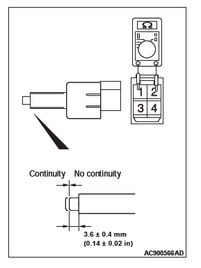
STEP 6. Stoplight switch continuity check
- Remove the stoplight switch (Refer to GROUP 35A −Brake Pedal).
- Connect the circuit tester (Ω range) to the stop light switch connector terminals No.1 and No.2.
- When no continuity is detected with the plunger pressed from the edge of the outer case by the dimension shown in the figure and when continuity is detected with the plunger released, the stop light switch is in good condition.
Q: Is the check result normal?
YES : Go to Step 7.
NO : Replace the stop light switch (Refer to GROUP 35A −Brake Pedal), and then go to Step 10.
STEP 7. Brake drag check
Check the brake system for drag (Refer to GROUP 35A − On-vehicle Service/Brake Drag Force Check).
Q: Is the check result normal?
YES : Go to Step 8.
NO : Repair the brake drag, and then go to Step 10.
STEP 8. Brake booster check
Q: Is the check result normal?
YES : Go to Step 9.
NO : Replace the brake booster (Refer to GROUP 35A − Master Cylinder Assembly and Brake Booster), and then go to Step 10.
STEP 9. Check whether the diagnostic trouble code is reset.
Q: Is DTC C121E set?
YES : Replace the hydraulic unit (integrated with ASC-ECU). Then go to Step 10.
NO : The trouble can be an intermittent malfunction (Refer to GROUP 00 − How to Use Troubleshooting/How to Cope with Intermittent Malfunctions).
STEP 10. Check whether the diagnostic trouble code is reset.
Erase the DTC.
Q: Is DTC C121E set?
YES : Return to Step 1.
NO : The procedure is complete.
DTC C1000: Abnormality in stoplight switch circuit
CAUTION
- If there is any problem in the CAN bus lines, an incorrect diagnostic trouble code may be set. Prior to this diagnosis, diagnose the CAN bus lines (Refer to GROUP 54C − CAN Bus Line Diagnostic Flow).
- Whenever ECU is replaced, ensure that the CAN bus lines are normal.
- When the hydraulic unit (integrated with ASC-ECU) is replaced, always carry out the calibration of the steering wheel sensor, the G and yaw rate sensor and brake fluid pressure sensor.
OPERATION
ETACS-ECU sends the ON signal generated when the brake pedal is depressed and OFF signal generated when it is released to ASC-ECU via the CAN bus lines.
DTC SET CONDITIONS
This diagnostic trouble code is set in the following case.
- When the vehicle has run for a long time with the stoplight switch turned ON.
- When there is difference between the stoplight state and the vehicle's behavior
PROBABLE CAUSES
- Malfunction of the stoplight relay
- Malfunction of the stoplight
- Damaged wiring harness and connectors
- ETACS-ECU malfunction
- ASC-ECU malfunction
DIAGNOSIS
Required Special Tools:
- MB991958 Scan Tool (M.U.T.-III Sub Assembly)
- MB991824: Vehicle Communication Interface (V.C.I.)
- MB991827 M.U.T.-III USB Cable
- MB991910 M.U.T.-III Main Harness A
STEP 1. Check that the stoplight of the rear combination light illuminates normally.
Q: Is the check result normal?
YES : Go to Step 2.
NO : Diagnose the rear combination light (Refer to GROUP 54A − Rear Combination Light/Trouble Symptom Chart). On completion, go to Step 2.
STEP 2. Using scan tool MB991958, diagnose the CAN bus lines.
Use M.U.T.-III to diagnose the CAN bus lines.
Q: Is the check result normal?
YES : Go to Step 4.
NO : Repair the CAN bus lines (Refer to GROUP 54C − CAN Bus Diagnostics Table). On completion, go to Step 3.
STEP 3. DTC recheck after resetting CAN bus lines
Q: Is DTC C1000 set?
YES : Go to Step 4.
NO : The procedure is complete.
STEP 4. Battery check
Q: Is the battery in good condition?
YES : Go to Step 5.
NO : Charge or replace the battery, and go to Step 10.
STEP 5. Connector check: C-312 ETACS-ECU connector
Q: Is the check result normal?
YES : Go to Step 6.
NO : Repair the damaged connector.
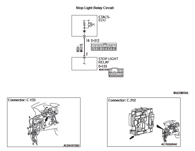
STEP 6. Measure the voltage at the C-312 ETACS-ECU connector.
- Measure by backprobing without disconnecting the ETACS-ECU connector and stoplight switch connector.
- Disconnecting the C-133 stoplight relay connector.
- Measure the voltage between the C-312 ETACS-ECU
connector terminal No.16 and the body ground.
OK:
When the brake pedal is released: Approximately 0 V − 5 V (pulse)
When the brake pedal is depressed: Approximately system voltage
Q: Is the check result normal?
YES : Go to Step 9.
NO : Go to Step 7.
STEP 7. Connector check: C-312 ETACS-ECU connector
Q: Is the check result normal?
YES : Go to Step 8.
NO : Repair the damaged connector.
STEP 8. Check the wiring harness between C-312 ETACS-ECU connector terminal No.16 and C-133 stoplight relay connector terminal No.2
- Check the signal line for open circuit.
Q: Is the check result normal?
YES : Go to Step 9.
NO : Replace the wiring harness.
STEP 9. Diagnostic trouble code recheck
Erase the DTC.
Q: Is diagnostic trouble code No.C1000 set?
YES : Replace the hydraulic unit (integrated with ASC-ECU). Then go to Step 10.
NO : Intermittent malfunction (Refer to GROUP 00 − How to Use Troubleshooting/How to Cope with Intermittent Malfunctions).
STEP 10. Diagnostic trouble code recheck
Erase the DTC.
Q: Is diagnostic trouble code No.C1000 set?
YES : Return to Step 1.
NO : The procedure is complete.
READ NEXT:
 Parking Brakes
General Information
The mechanical rear-wheel acting type parking brake
is adopted, and a parking brake lever is used for that
operation.
CONSTRUCTION DIAGRAM
<2.4L Engine: 5 persons seat>
<2
Power Steering
General Information
The steering wheel has three spokes and is
equipped with SRS (Supplemental Restraint System).
The steering column has a shock absorbing
mechanism and a tilt steering mechanism
Power Steering Diagnosis
INTRODUCTION TO POWER STEERING DIAGNOSIS
Hydraulic power steering is used for all vehicles.
Faults in the power steering can include excessive
play of the steering wheel, difficult steering wheel
ope
SEE MORE:
Windshield Wiper, Windshield Washer
WINDSHIELD WIPER
REMOVAL AND INSTALLATION
Wiper blade removal steps
Wiper blade assembly
Wiper blade
Windshield wiper motor and link
assembly removal steps
Wiper arm and blade assembly
Hood weatherstrip rear
Front deck garnish
Windshield wiper link
Wiper motor link plate
Windshield wiper
Door Assembly, Door Glass and Regulator, Door Handle and Latch
Door Assembly
REMOVAL AND INSTALLATION
Post-installation operation
Door adjustment
<Front door>
Damper removal
Damper
Door assembly and front door
hinge removal steps
Front scuff plate, cowl side trim
Wiring harness connector
connection
Door check connecting bolt
Door assembly
