Mitsubishi Outlander: Symptom Procedures
Inspection Procedure 1: None of headlights (low-beam) illuminates.
CAUTION Whenever the ECU is replaced, ensure that the power supply circuit, the ground circuit and the communication circuit are normal.
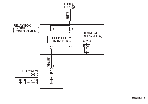
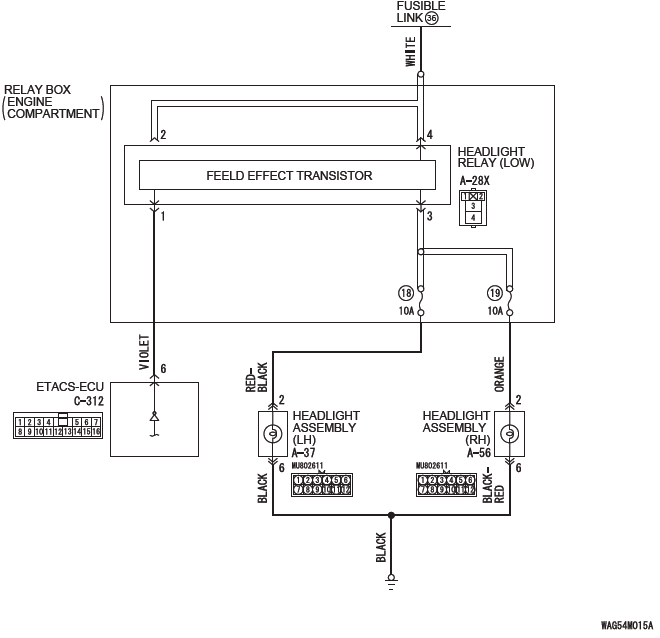
Headlight Relay (Low-Beam) Circuit <Halogen Type>
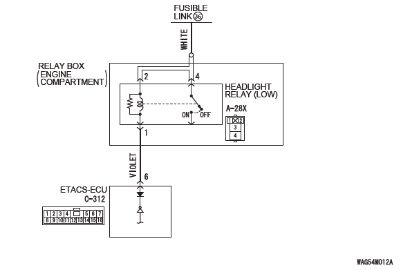
Headlight Relay (Low-Beam) Circuit <Discharge Type>
TECHNICAL DESCRIPTION (COMMENT)
If none of headlights (low-beam) illuminates, the headlight switch input circuit, headlight relay (LOW), or ETACS-ECU may have a problem.
TROUBLESHOOTING HINTS
- Malfunction of column switch
- Malfunction of headlight relay (LOW)
- Malfunction of the ETACS-ECU
- Damaged harness wires and connectors
DIAGNOSIS
Required Special Tools:
- MB992006: Extra fine probe
- MB991223: Harness set
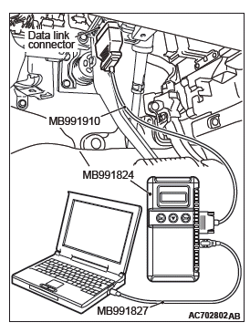
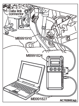
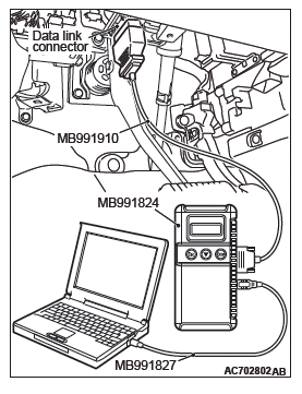
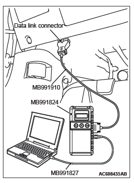
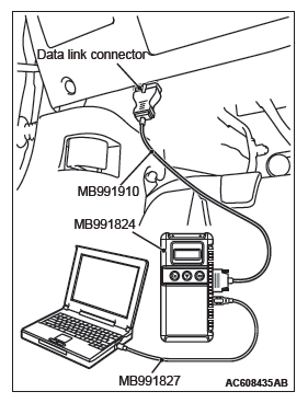
- MB991958 Scan Tool (M.U.T.-III Sub Assembly)
- MB991824: Vehicle Communication Interface (V.C.I.)
- MB991827 M.U.T.-III USB Cable
- MB991910 M.U.T.-III Main Harness A (Vehicles with CAN communication system)
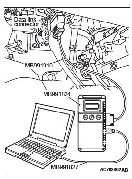
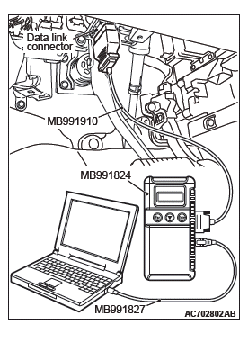
STEP 1. Using scan tool MB991958, read the diagnostic trouble code.
CAUTION To prevent damage to scan tool MB991958, always turn the ignition switch to the "LOCK" (OFF) position before connecting or disconnecting scan tool MB991958.
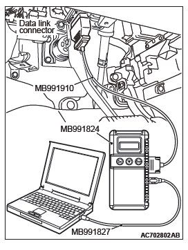
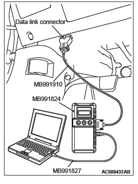
(1) Connect scan tool MB991958. Refer to "How to connect scan too (M.U.T.-III)".
(2) Turn the ignition switch to the "ON" position.
(3) Check whether the ETACS-ECU related DTC is set.
(4) Turn the ignition switch to the "LOCK" (OFF) position.
Q: Is the DTC set?
YES : Diagnose the ETACS-ECU. NO : Go to Step 2.
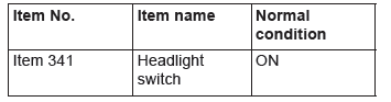
STEP 2. Using scan tool MB991958, check data list.
Use the ETACS-ECU service data to check the signals related to the operation of headlight function.
- Turn the headlight switch to the ON position.
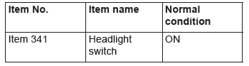
Q: Does scan tool MB991958 display the items "Headlight switch" as normal condition?
YES : Go to Step 3.
NO : Troubleshoot the ETACS-ECU.
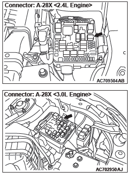
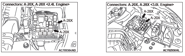
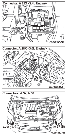
STEP 3. Check headlight relay (LOW) connector A-28X for loose, corroded or damaged terminals, or terminals pushed back in the connector.
Q: Is headlight relay (LOW) connector A-28X in good condition?
YES : Go to Step 4.
NO : Repair the damaged parts.
STEP 4. Check the battery power supply circuit to the headlight relay (LOW). Measure the voltage at headlight relay (LOW) connector A-28X.
CAUTION The top and bottom of the headlight relay (LOW) are difficult to identify. Prior to inspection, confirm the triangle mark on the relay box.
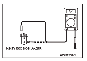
(1) Disconnect headlight relay (LOW) connector A-28X and measure the voltage available at the relay box side of the connector.
(2) Measure the voltage between terminal 2/4 and ground.
- The voltage should measure approximately 12 volts (battery positive voltage).
Q: Is the measured voltage approximately 12 volts (battery positive voltage)?
YES : Go to Step 5.
NO : Go to Step 7.
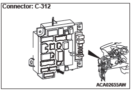
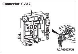
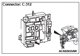
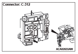
STEP 5. Check ETACS-ECU connector C-312 for loose, corroded or damaged terminals, or terminals pushed back in the connector.
Q: Is ETACS-ECU connector C-312 in good condition?
YES : Go to Step 6.
NO : Repair the damaged parts.
STEP 6. Check the wiring harness between headlight relay (LOW) connector A-28X (terminal 1) and ETACS-ECU connector C-312 (terminal 6).
- Check the ground wires for open circuit.
Q: Is the wiring harness between headlight relay (LOW) connector A-28X (terminal 1) and ETACS-ECU connector C-312 (terminal 6) in good condition?
YES (Vehicles without discharge headlight) : Go to Step 8.
YES (Vehicles with discharge headlight) : Go to Step 9.
NO : The wiring harness may be damaged or the connector(s) may have loose, corroded or damaged terminals, or terminals pushed back in the connector.
Repair the wiring harness as necessary. Verify that the low-beam headlights illuminate normally.
STEP 7. Check the wiring harness between headlight relay (LOW) connector A-28X (terminal 2/4) and the fusible link (36).
- Check the power supply line for open circuit.
Q: Is the wiring harness between headlight relay (LOW) connector A-28X (terminal 2/4) and fusible link (36) in good condition?
YES (Vehicles without discharge headlight) : Go to Step 8.
YES (Vehicles with discharge headlight) : Go to Step 9.
NO : The wiring harness may be damaged or the connector(s) may have loose, corroded or damaged terminals, or terminals pushed back in the connector.
Repair the wiring harness as necessary. Verify that the low-beam headlights illuminate normally.
STEP 8. Substitute a known good headlight relay (LOW), and check the trouble symptom.
Q: Do the headlights (low-beam) illuminate in good condition?
YES : Replace the headlight relay (LOW).
NO : Replace the ETACS-ECU.
STEP 9. Check of headlight relay (LOW).
Q: Is the headlight relay (LOW) in good condition?
YES : Go to Step 10.
NO : Replace the headlight relay (LOW). Verify that the low-beam headlights illuminate normally.
STEP 10. Retest the system.
Q: Do the headlights (low-beam) illuminate in good condition?
YES : The trouble can be an intermittent malfunction.
NO : Replace the ETACS-ECU.
Inspection Procedure 2: None of headlights (high-beam) illuminates.
CAUTION Whenever the ECU is replaced, ensure that the power supply circuit, the ground circuit and the communication circuit are normal.
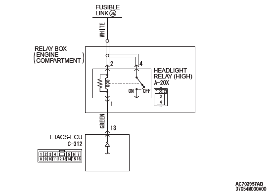
Headlight Relay (High-Beam) Circuit
TECHNICAL DESCRIPTION (COMMENT)
If none of headlights (high-beam) illuminates, the headlight switch input circuit, headlight relay (HIGH), or ETACS-ECU may have a problem.
TROUBLESHOOTING HINTS
- Malfunction of column switch
- Malfunction of headlight relay (HIGH)
- Malfunction of the ETACS-ECU
- Damaged harness wires and connectors
DIAGNOSIS
Required Special Tools:
- MB992006: Extra fine probe
- MB991223: Harness set
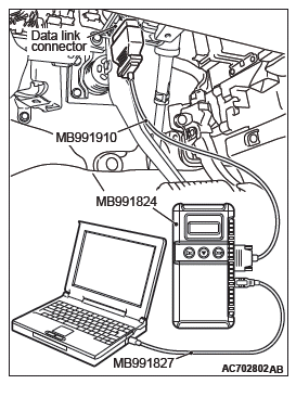
- MB991958 Scan Tool (M.U.T.-III Sub Assembly)
- MB991824: Vehicle Communication Interface (V.C.I.)
- MB991827 M.U.T.-III USB Cable
- MB991910 M.U.T.-III Main Harness A (Vehicles with CAN communication system)
STEP 1. Using scan tool MB991958, read the diagnostic trouble code.
CAUTION To prevent damage to scan tool MB991958, always turn the ignition switch to the "LOCK" (OFF) position before connecting or disconnecting scan tool MB991958.
(1) Connect scan tool MB991958. Refer to "How to connect scan too (M.U.T.-III)".
(2) Turn the ignition switch to the "ON" position.
(3) Check whether the ETACS-ECU related DTC is set.
(4) Turn the ignition switch to the "LOCK" (OFF) position.
Q: Is the DTC set?
YES : Diagnose the ETACS-ECU.
NO : Go to Step 2.
STEP 2. Using scan tool MB991958, check data list.
Use the ETACS-ECU service data to check the signals related to the operation of headlight function.
- Turn the headlight switch to the ON position.
- Turn the passing switch to the ON position.
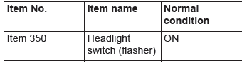
Q: Do scan tool MB991958 display the items "Headlight switch" and "Headlight switch (flasher)" as normal condition?
YES : (Normal conditions are displayed for all items.) Go to Step 3.
NO : (Normal condition is not displayed.) Troubleshoot the ETACS-ECU. Refer to ETACS, Diagnosis.
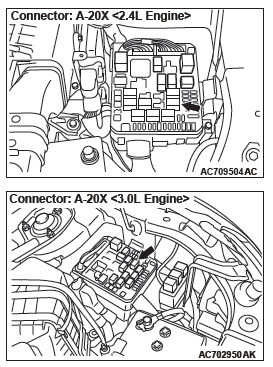
STEP 3. Check headlight relay (HIGH) connector A-20X for loose, corroded or damaged terminals, or terminals pushed back in the connector.
Q: Is headlight relay (HIGH) connector A-20X in good condition?
YES : Go to Step 4.
NO : Repair the damaged parts.
STEP 4. Check of headlight relay (HIGH).
Q: Is the headlight relay (HIGH) in good condition?
YES : Go to Step 5.
NO : Replace the headlight relay (HIGH). Verify that the high-beam headlights illuminate normally.
STEP 5. Check the battery power supply circuit to the headlight relay (HIGH). Measure the voltage at headlight relay (HIGH) connector A-20X.
CAUTION The top and bottom of the headlight relay (HIGH) are difficult to identify. Prior to inspection, confirm the triangle mark on the relay box.
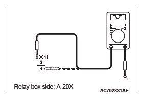
(1) Disconnect headlight relay (HIGH) connector A-20X and measure the voltage available at the relay box side of the connector.
(2) Measure the voltage between terminal 2/4 and ground.
- The voltage should measure approximately 12 volts (battery positive voltage).
Q: Is the measured voltage approximately 12 volts (battery positive voltage)?
YES : Go to Step 6.
NO : Go to Step 8.
STEP 6. Check ETACS-ECU connector C-312 for loose, corroded or damaged terminals, or terminals pushed back in the connector.
Q: Is ETACS-ECU connector C-312 in good condition?
YES : Go to Step 7.
NO : Repair the damaged parts.
STEP 7. Check the wiring harness between headlight relay (HIGH) connector A-20X (terminal 1) and ETACS-ECU connector C-312 (terminal 13).
- Check the ground wires for open circuit.
Q: Is the wiring harness between headlight relay (HIGH) connector A-20X (terminal 1) and ETACS-ECU connector C-312 (terminal 13) in good condition?
YES : Go to Step 9.
NO : The wiring harness may be damaged or the connector(s) may have loose, corroded or damaged terminals, or terminals pushed back in the connector.
Repair the wiring harness as necessary. Verify that the high-beam headlights illuminate normally.
STEP 8. Check the wiring harness between headlight relay (HIGH) connector A-20X (terminal 2/4) and the fusible link (36).
- Check the power supply line for open circuit.
Q: Is the wiring harness between headlight relay (HIGH) connector A-20X (terminal 2/4) and fusible link (36) in good condition?
YES : Go to Step 9.
NO : The wiring harness may be damaged or the connector(s) may have loose, corroded or damaged terminals, or terminals pushed back in the connector.
Repair the wiring harness as necessary. Verify that the high-beam headlights illuminate normally.
STEP 9. Retest the system
Q: Do the headlights (high-beam) illuminate in good condition?
YES : The trouble can be an intermittent malfunction.
NO : Replace the ETACS-ECU.
Inspection Procedure 3: The headlights illuminate at low-beam (high-beam does not illuminate) regardless of the lighting switch positions.
CAUTION Whenever the ECU is replaced, ensure that the power supply circuit, the ground circuit and the communication circuit are normal.
TECHNICAL DESCRIPTION (COMMENT)
If the headlights illuminate only at low-beam regardless of the lighting switch position, the headlight fail-safe function may be active.
TROUBLESHOOTING HINTS
- Malfunction of column switch
- Malfunction of the ETACS-ECU
- Damaged harness wires and connectors
DIAGNOSIS
Required Special Tools:
- MB991958: Scan Tool (M.U.T.-III Sub Assembly)
- MB991824: Vehicle Communication Interface (V.C.I.)
- MB991827: M.U.T.-III USB Cable
- MB991910: M.U.T.-III Main Harness A (Vehicles with CAN communication system)
STEP 1. Using scan tool MB991958, read the ETACS-ECU diagnostic trouble code.
CAUTION To prevent damage to scan tool MB991958, always turn the ignition switch to the "LOCK" (OFF) position before connecting or disconnecting scan tool MB991958.
(1) Connect scan tool MB991958. Refer to "How to connect scan too (M.U.T.-III)".
(2) Turn the ignition switch to the "ON" position.
(3) Check whether the ETACS-ECU related DTC is set.
(4) Turn the ignition switch to the "LOCK" (OFF) position.
Q: Is the DTC set?
YES : Diagnose the ETACS-ECU. Refer to ETACS, Diagnosis.
NO : Go to Step 2.
STEP 2. Retest the system.
Q: Do the headlights illuminate normally?
YES : The trouble can be an intermittent malfunction.
NO : Replace the ETACS-ECU.
Inspection Procedure 4: Headlights do not illuminate when the passing switch is operate.
CAUTION Whenever the ECU is replaced, ensure that the power supply circuit, the ground circuit and the communication circuit are normal.
TECHNICAL DESCRIPTION (COMMENT)
If both headlights (low-beam and high-beam) do not illuminate, the passing switch input circuit or ETACS-ECU may have a problem.
TROUBLESHOOTING HINTS
- Malfunction of column switch
- Malfunction of the ETACS-ECU
- Damaged harness wires and connectors
DIAGNOSIS
Required Special Tools:
- MB991223: Harness set
- MB991958: Scan Tool (M.U.T.-III Sub Assembly)
- MB991824: Vehicle Communication Interface (V.C.I.)
- MB991827: M.U.T.-III USB Cable
- MB991910: M.U.T.-III Main Harness A (Vehicles with CAN communication system)
STEP 1. Check that the headlights operate.
Check that the low-beam and high-beam headlights illuminate normally.
Q: Is the check result normal?
YES : Go to Step 2.
NO : Refer to Inspection Procedure 1 "None of headlights (low-beam) illuminates" and Inspection Procedure 2 "None of headlights (high-beam) illuminates".
STEP 2. Using scan tool MB991958, read the ETACS-ECU diagnostic trouble code.
CAUTION To prevent damage to scan tool MB991958, always turn the ignition switch to the "LOCK" (OFF) position before connecting or disconnecting scan tool MB991958.
(1) Connect scan tool MB991958. Refer to "How to connect scan too (M.U.T.-III)".
(2) Turn the ignition switch to the "ON" position.
(3) Check whether the ETACS-ECU related DTC is set.
(4) Turn the ignition switch to the "LOCK" (OFF) position.
Q: Is the DTC set?
YES : Diagnose the ETACS-ECU.
NO : Go to Step 3.
STEP 3. Retest the system.
Q: Do the headlights (low-beam and high-beam) illuminate normally when turning ON the passing switch?
YES : The trouble can be an intermittent malfunction.
NO : Replace the ETACS-ECU.
Inspection Procedure 5: One of the headlights does not illuminate.
CAUTION If the discharge type headlights do not illuminate, fully understand the precautions in "Service precautions for discharge headlight" before proceeding with the troubleshooting.
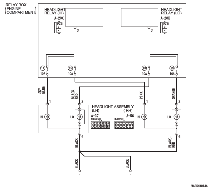
Headlight Circuit <Halogen Type>
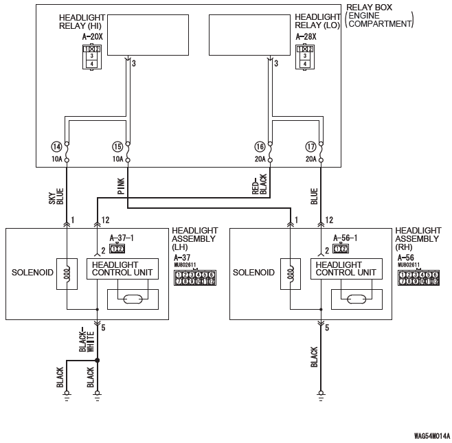
Headlight Circuit <Discharge Type>
TECHNICAL DESCRIPTION (COMMENT)
When one of the headlights does not illuminate, the wiring harness, connector(s), or the bulb may have a problem, or the fuse may be burned out.
TROUBLESHOOTING HINTS
- Malfunction of the headlight bulbs
- Malfunction of the headlight assembly
- Malfunction of the headlamp control unit
- Damaged harness wires and connectors
DIAGNOSIS
Required Special Tools:
- MB992006: Extra fine probe
- MB991223: Harness set
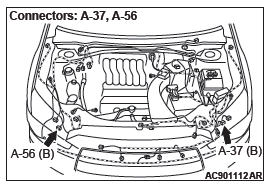
STEP 1. Check headlight (LOW) connector A-37 <LH>, A-56 <RH> for loose, corroded or damaged terminals, or terminals pushed back in the connector.
Q: Is headlight (LOW) assembly connector A-37 <LH>, A-56 <RH> in good condition?
YES : Go to Step 2.
NO : Repair the defective connector.
STEP 2. Check bulb.
Check the bulb(s) of headlight that does not illuminate.
NOTE: If discharge-type lower beam headlights do not illuminate, their bulbs cannot be inspected. In this case, assume the bulbs to be normal and proceed with steps.
Q: Is the bulb in good condition?
YES : Go to Step 3.
NO : Replace the bulb(s) of the light that does not illuminate.
STEP 3. Check the ground circuit to the headlight assembly (LOW). Measure the resistance at headlight assembly (LOW) connector A-37 <LH>, A-56 <RH>.
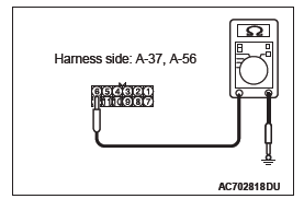
(1) Disconnect the connector, and measure at the wiring harness side.
(2) Resistance between the connector of light which does not illuminate and ground.
- Resistance between the A-37 (LH), A-56 (RH) headlight assembly connector terminal 6 and ground. <Halogen headlight (LOW)>
- Resistance between the A-37 (LH), A-56 (RH) headlight
assembly connector terminal 5 and ground. <Discharge
headlight (LOW)>
OK: The resistance should be 2 Ω or less.
Q: Is the measured resistance 2 Ω or less?
YES : Go to Step 5.
NO : Go to Step 4.
STEP 4. Check the wiring harness between headlight assembly (LOW) connector A-37 <LH>, A-56 <RH> (terminal 6 <halogen headlight> or 5 <discharge headlight>) and ground.
- Check the ground wires for open circuit.
Q: Is the wiring harness between headlight assembly (LOW) connector A-37 <LH>, A-56 <RH> (terminal 6 <halogen headlight> or 5 <discharge headlight>) and ground in good condition?
YES : The trouble can be an intermittent malfunction.
NO : The wiring harness may be damaged or the connector(s) may have loose, corroded or damaged terminals, or terminals pushed back in the connector.
Repair the wiring harness as necessary. Verify that the headlights illuminate normally.
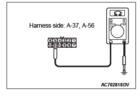
STEP 5. Check the wiring harness between headlight assembly (LOW) connector A-37 <LH>, A-56 <RH> (terminal 1 and 2 <halogen headlight> or 1 and 12 <discharge headlight>) and headlight relay (LOW) connector A-28X or headlight relay (HIGH) connector A-20X (terminal 3).
- Check the power supply line for open circuit.
Q: Is the wiring harness between headlight assembly (LOW) connector A-37 <LH>, A-56 <RH> (terminal 1 and 2 <halogen headlight> or 1 and 12 <discharge headlight>) and headlight relay (LOW) connector A-28X or headlight relay (HIGH) connector A-20X (terminal 3) in good condition?
YES : Replace the headlight assembly that does not illuminate.
NO : The wiring harness may be damaged or the connector(s) may have loose, corroded or damaged terminals, or terminals pushed back in the connector.
Repair the wiring harness as necessary. Verify that the headlights illuminate normally.
Inspection Procedure 6: High-beam indicator light does not illuminate normally.
CAUTION Whenever the ECU is replaced, ensure that the power supply circuit, the ground circuit and the communication circuit are normal.
TECHNICAL DESCRIPTION (COMMENT)
If the high-beam indicator does not illuminate normally, the harness in the CAN bus lines, connector(s), ETACS-ECU, or combination meter may have a problem.
TROUBLESHOOTING HINTS
- Malfunction of the ETACS-ECU
- Malfunction of combination meter
- Damaged harness wires and connectors
DIAGNOSIS
Required Special Tools:
- MB991958 Scan Tool (M.U.T.-III Sub Assembly)
- MB991824: Vehicle Communication Interface (V.C.I.)
- MB991827 M.U.T.-III USB Cable
- MB991910 M.U.T.-III Main Harness A (Vehicles with CAN communication system)
STEP 1. Check of headlight (high-beam).
Check that the headlights (high-beam) illuminate/extinguish normally when the lighting switch is operated.
Q: Is the check result normal?
YES : Go to Step 2.
NO : Refer to Inspection Procedure 2 "None of headlights (high-beam) illuminates".
STEP 2. Using scan tool MB991958, diagnose the CAN bus line.
CAUTION To prevent damage to scan tool MB991958, always turn the ignition switch to the "LOCK" (OFF) position before connecting or disconnecting scan tool MB991958.
(1) Connect scan tool MB991958. Refer to "How to connect the Scan Tool (M.U.T.-III)".
(2) Turn the ignition switch from "LOCK" (OFF) position to "ON" position.
(3) Diagnose the CAN bus line.
(4) Turn the ignition switch to the "LOCK" (OFF) position.
Q: Is the CAN bus line found to be normal?
YES : Go to Step 3.
NO : Repair the CAN bus line.
STEP 3. Using scan tool MB991958, read the ETACS-ECU diagnostic trouble code.
(1) Connect scan tool MB991958. Refer to "How to connect scan too (M.U.T.-III)".
(2) Turn the ignition switch to the "ON" position.
(3) Check whether the ETACS-ECU related DTC is set.
(4) Turn the ignition switch to the "LOCK" (OFF) position.
Q: Is the DTC set?
YES : Diagnose the ETACS-ECU. Refer to ETACS, Diagnosis.
NO : Go to Step 4.
STEP 4. Using scan tool MB991958, check actuator test.
(1) Turn the ignition switch to the "ON" position.
(2) Perform the actuator test for the combination meter, and check that the high-beam indicator light illuminates.
(3) Turn the ignition switch to the "LOCK" (OFF) position.
Q: Is the check result normal?
YES : Replace the ETACS-ECU.
NO : Replace the combination meter.
Inspection Procedure 7: The headlight automatic shutdown function does not work normally.
CAUTION Whenever the ECU is replaced, ensure that the power supply circuit, the ground circuit and the communication circuit are normal.
OPERATION
The ETACS-ECU operates this function in accordance with the input signals from column switch (lighting switch), ignition switch (IG1), and front door switch (LH).
TECHNICAL DESCRIPTION (COMMENT)
If the headlight automatic shutdown function does not work normally, the above described input circuits or ETACS-ECU may have a problem. Also, it may be possible that the headlight automatic shutdown function is set to "Disable" through configuration function.
TROUBLESHOOTING HINTS
- Malfunction of front door switch (LH)
- Malfunction of the ETACS-ECU
- The wiring harness or connectors may have loose, corroded, or damaged terminals, or terminals pushed back in the connector
DIAGNOSIS
Required Special Tools:
- MB991958: Scan Tool (M.U.T.-III Sub Assembly)
- MB991824: Vehicle Communication Interface (V.C.I.)
- MB991827: M.U.T.-III USB Cable
- MB991910: M.U.T.-III Main Harness A (Vehicles with CAN communication system)
STEP 1. Using scan tool MB991958, Check the configuration function.
Use the ETACS-ECU configuration function to check that the "Head light auto cut customize" is set to "Enable (C-spec.)"
CAUTION To prevent damage to scan tool MB991958, always turn the ignition switch to the "LOCK" (OFF) position before connecting or disconnecting scan tool MB991958.
(1) Connect scan tool MB991958. Refer to "How to connect the scan tool (M.U.T.-III)".
(2) Turn the ignition switch to the "ON" position.
(3) Use the ETACS-ECU configuration function to check that the "Headlight auto cut customize" is set to "Enable (C-spec.)"
(4) Turn the ignition switch to the "LOCK" (OFF) position.
Q: Is the check result normal?
YES : Go to Step 2.
NO : Use the ETACS-ECU configuration function to set the "Headlight auto cut customize" to "Enable (C-spec.)".
STEP 2. Using scan tool MB991958, read the diagnostic trouble code.
(1) Turn the ignition switch to the "ON" position.
(2) Check whether the ETACS-ECU related DTC is set.
(3) Turn the ignition switch to the "LOCK" (OFF) position.
Q: Is the DTC set?
YES : Diagnose the ETACS-ECU. Refer to ETACS, Diagnosis.
NO : Go to Step 3.
STEP 3. Using scan tool MB991958, check data list.
Use the ETACS-ECU service data to check the signals related to the operation of headlight automatic shutdown function.
- Turn the ignition switch to the LOCK (OFF) position.
- Illuminate the headlights.
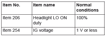
- Open the driver's door.
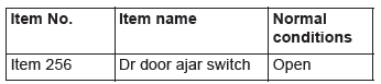
Q: Does scan tool MB991958 display the items "Head light LO ON duty", "IG voltage" and "Dr door ajar switch" as normal condition?
YES <Normal conditions are displayed for all items.> : Go to Step 4.
NO <Normal condition is not displayed for item No.206.> : Troubleshoot the ETACS-ECU. Refer to Diagnosis - Inspection Procedure 12 "ETACS-ECU does not receive any signal from the column switch signal".
NO <Normal condition is not displayed for item No.254.> : Troubleshoot the ETACS-ECU. Refer to Diagnosis - Inspection Procedure 2 "ETACS-ECU does not receive any signal from the ignition switch (IG1)".
NO <Normal condition is not displayed for item No.256.> : Troubleshoot the ETACS-ECU. Refer to Diagnosis - Inspection Procedure 5 "ETACS-ECU does not receive any signal from the front door switch (LH)".
STEP 4. Retest the system.
Check that the headlight automatic shutdown function works normally.
Q: Is the check result normal?
YES : The trouble can be an intermittent malfunction.
NO : Replace the ETACS-ECU.
Inspection Procedure 8: Daytime running light function does not work normally. <Halogen type headlight>
CAUTION Whenever the ECU is replaced, ensure that the input and output signal circuits are normal.
Daytime Running Light Circuit
TECHNICAL DESCRIPTION (COMMENT)
If the daytime running light function does not work, connector(s), wiring harness in the CAN bus lines, the engine control module, the combination meter, the headlight relay (LOW), the ETACS-ECU or the input signal circuit may be defective.
TROUBLESHOOTING HINTS
- Trouble in input signal system
- Malfunction of headlight relay (LOW)
- Malfunction of the ETACS-ECU
- Damaged harness wires and connectors
DIAGNOSIS
Required Special Tools:
- MB991223: Harness Set
- MB992006: Extra Fine Probe
- MB991958: Scan Tool (M.U.T.-III Sub Assembly)
- MB991824: V.C.I.
- MB991827: M.U.T.-III USB Cable
- MB991910: M.U.T.-III Main Harness A
STEP 1. Verify the headlight (low-beam) operation.
Check to see that the headlight (low-beam) lights up properly when operating the dimmer switch while the headlight switch is ON.
Q: Do the headlights (low-beam) illuminate normally?
YES : Go to Step 2.
NO : Refer to Inspection Procedure 1 "None of headlights (low-beam) illuminates".
STEP 2. Using scan tool MB991958, diagnose the CAN bus line.
CAUTION To prevent damage to scan tool MB991958, always turn the ignition switch to the "LOCK" (OFF) position before connecting or disconnecting scan tool MB991958.
(1) Connect scan tool MB991958. Refer to "How to connect scan too (M.U.T.-III)".
(2) Turn the ignition switch to the "ON" position.
(3) Diagnose the CAN bus line.
(4) Turn the ignition switch to the "LOCK" (OFF) position.
Q: Is the CAN bus line found to be normal?
YES : Go to Step 3.
NO : Repair the CAN bus line.
STEP 3. Using scan tool MB991958, read the ETACS-ECU diagnostic trouble code.
Check whether ETACS-ECU DTCs are set.
(1) Turn the ignition switch to the "ON" position.
(2) Check for ETACS-ECU DTCs.
(3) Turn the ignition switch to the "LOCK" (OFF) position.
Q: Is the DTC set?
YES : Diagnose the ETACS-ECU. Refer to ETACS, Diagnosis.
NO : Go to Step 4.
STEP 4. Using scan tool MB991958, read the MFI system diagnostic trouble code.
Check whether engine control module DTCs are set or not.
(1) Turn the ignition switch to the "ON" position.
(2) Check for engine control module DTCs.
(3) Turn the ignition switch to the "LOCK" (OFF) position.
Q: Is the DTC set?
YES : Diagnose the MFI system.
NO : Go to Step 5.
STEP 5. Check the parking brake switch.
Check the input signals from the parking brake switch.
(1) Turn the ignition switch to the "ON" position.
(2) Check that the brake warning light on the combination meter goes off when the parking brake lever is released.
(3) Turn the ignition switch to the "LOCK" (OFF) position.
Q: Does the brake warning light go off?
YES : Go to Step 6.
NO : Refer to GROUP 36, Diagnosis, Inspection Procedure 2. Verify that the daytime running light function does not work normally.
STEP 6. Temporarily replace the headlight relay (LOW), and retest the system.
After temporarily replacing the headlight relay (LOW), with the ignition switch being in the ON position (engine is running), release the parking brake (parking brake switch: OFF) and turn the lighting switch to the OFF or TAIL position, and then check if the headlights (low-beam) illuminate with a reduced beam state.
Q: Do the headlights (low-beam) illuminate in good condition?
YES : Replace the headlight relay (LOW).
NO : Replace the ETACS-ECU.
Inspection Procedure 8: Daytime running light function does not work normally. <Discharge type headlight>
CAUTION Whenever the ECU is replaced, ensure that the input and output signal circuits are normal.
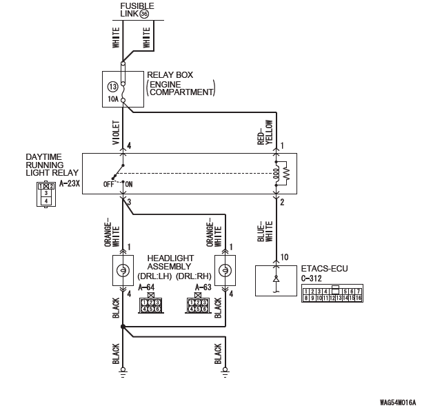
Daytime Running Light Circuit
COMMENTS ON TROUBLE SYMPTOM
If the daytime running lights do not illuminate, the wiring harness connector(s), the bulb or the ETACS-ECU may have a problem.
PROBABLE CAUSES
- Burned-out daytime running light bulb
- Malfunction of the daytime running light relay
- Malfunction of the ETACS-ECU
- Damaged harness wires and connectors
DIAGNOSIS
Required Special Tools:
- MB991223: Harness Set
- MB992006: Extra Fine Probe
- MB991958: Scan Tool (M.U.T.-III Sub Assembly)
- MB991824: V.C.I.
- MB991827: M.U.T.-III USB Cable
- MB991910: M.U.T.-III Main Harness A
STEP 1. Check that the tail/stop lights and headlights operate.
Check that the tail/stop lights and headlights illuminate normally.
Q: Do the tail/stop lights and headlights operate normally?
YES : Go to Step 2.
NO : Check the tail/stop lights and the headlights.
STEP 2. Check the daytime running light bulb.
(1) Remove the daytime running light bulb.
(2) Verify that the daytime running light bulb is not damaged or burned out.
Q: Is the daytime running light bulb in good condition?
YES : Go to Step 3.
NO : Replace the fog light bulb. Verify that the daytime running lights illuminate normally.
STEP 3. Using scan tool MB991958, diagnose the CAN bus line.
CAUTION To prevent damage to scan tool MB991958, always turn the ignition switch to the "LOCK" (OFF) position before connecting or disconnecting scan tool MB991958.
(1) Connect scan tool MB991958. Refer to "How to connect scan too (M.U.T.-III)".
(2) Turn the ignition switch to the "ON" position.
(3) Diagnose the CAN bus line.
(4) Turn the ignition switch to the "LOCK" (OFF) position.
Q: Is the CAN bus line found to be normal?
YES : Go to Step 4.
NO : Repair the CAN bus line.
STEP 4. Using scan tool MB991958, read the ETACS-ECU diagnostic trouble code.
Check whether ETACS-ECU DTCs are set.
(1) Turn the ignition switch to the "ON" position.
(2) Check for ETACS-ECU DTCs.
(3) Turn the ignition switch to the "LOCK" (OFF) position.
Q: Is the DTC set?
YES : Diagnose the ETACS-ECU. Refer to ETACS, Diagnosis.
NO : Go to Step 5.
STEP 5. Using scan tool MB991958, read the MFI system diagnostic trouble code.
Check whether engine control module DTCs are set or not.
(1) Turn the ignition switch to the "ON" position.
(2) Check for engine control module DTCs.
(3) Turn the ignition switch to the "LOCK" (OFF) position.
Q: Is the DTC set?
YES : Diagnose the MFI system. Refer to GROUP 13B, Diagnosis.
NO : Go to Step 6.
STEP 6. Check the parking brake switch.
Check the input signals from the parking brake switch.
(1) Turn the ignition switch to the "ON" position.
(2) Check that the brake warning light on the combination meter goes off when the parking brake lever is released.
(3) Turn the ignition switch to the "LOCK" (OFF) position.
Q: Does the brake warning light go off?
YES : Go to Step 7.
NO : Refer to GROUP 36, Diagnosis, Inspection Procedure 2. Verify that the daytime running light function does not work normally.
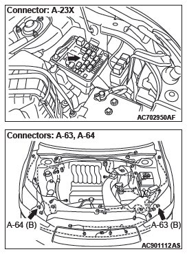
STEP 7. Check headlight assembly (DRL:LH) connector A-64, headlight assembly (DRL:RH) A-63 for loose, corroded or damaged terminals, or terminals pushed back in the connector.
Q: Is headlight assembly (DRL:LH) connector A-64, headlight assembly (DRL:RH) A-63 in good condition?
YES : Go to Step 8.
NO : Repair the damaged parts.
STEP 8. Check the ground circuit to the headlight assembly (DRL:LH) or headlight assembly (DRL:RH).
Measure the resistance at headlight assembly (DRL:LH) connector A-64 or headlight assembly (DRL:RH) connector A-63.
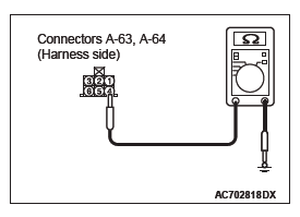
(1) Disconnect the connector, and measure at the wiring harness side.
(2) Check the resistance between the headlight assembly connector and ground.
- Resistance between A-64 headlight assembly (DRL:LH) connector terminal No.4 and ground
- Resistance between A-63 headlight assembly (DRL:RH) connector terminal No.4 and ground
OK: The resistance should be 2 ohm or less.
Q: Is the measured resistance 2 ohms or less?
YES : Go to Step 10.
NO : Go to Step 9.
STEP 9. Check the wiring harness between headlight assembly (DRL:LH) connector A-64 (terminal 4) or headlight assembly (DRL:RH) connector A-63 (terminal 4) and ground.
- Check the ground wires for open circuit.
Q: Is the wiring harness between headlight assembly (DRL:LH) connector A-64 (terminal 4) or headlight assembly (DRL:RH) connector A-63 (terminal 4) and ground in good condition?
YES : The trouble can be an intermittent malfunction.
NO : The wiring harness may be damaged or the connector(s) may have loose, corroded or damaged terminals, or terminals pushed back in the connector.
Repair the wiring harness as necessary. Verify that the daytime running lights illuminate normally.
STEP 10. Check daytime running light relay connector A-23X for loose, corroded or damaged terminals, or terminals pushed back in the connector.
Q: Is daytime running light relay connector A-23X in good condition?
YES : Go to Step 11.
NO : Repair or replace the damaged component(s).
STEP 11. Check the daytime running light relay. Q: Is the daytime running light relay in good condition?
YES : Go to Step 12.
NO : Replace the daytime running light relay. Verify that the daytime running lights illuminate normally.
STEP 12. Check the battery power supply circuit to the daytime running light relay. Measure the voltage at daytime running light relay connector A-23X.
CAUTION The top and bottom of the daytime running light relay are difficult to identify. Prior to inspection, confirm the triangle mark on the relay box.
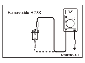
(1) Disconnect daytime running light relay connector A-23X and measure the voltage available at the relay box side of the connector.
(2) Measure the voltage between terminal 1 and ground, and also between terminal 4 and ground.
OK: The voltage should measure approximately 12 volts (battery positive voltage).
Q: Is the measured voltage approximately 12 volts (battery positive voltage)?
YES : Go to Step 14.
NO : Go to Step 13.
STEP 13. Check the wiring harness between daytime running light relay connector A-23X (terminal 1 and 4) and fusible link (36).
- Check the power supply line for open circuit.
Q: Is the wiring harness between daytime running light relay connector A-23X (terminal 1 and 4) and fusible link (36) in good condition?
YES : The trouble can be an intermittent malfunction.
NO : The wiring harness may be damaged or the connector(s) may have loose, corroded or damaged terminals, or terminals pushed back in the connector.
Repair the wiring harness as necessary. Verify that the daytime running lights illuminate normally.
STEP 14. Check ETACS-ECU connector C-312 for loose, corroded or damaged terminals, or terminals pushed back in the connector.
Q: Is ETACS-ECU connector C-312 in good condition?
YES : Go to Step 15.
NO : Repair or replace the damaged component(s).
STEP 15. Check the wiring harness between daytime running light relay connector A-23X (terminal 2) and ETACS-ECU connector C-312 (terminal 10).
- Check the communication wires for open circuit.
Q: Is the wiring harness between daytime running light relay connector A-23X (terminal 2) and ETACS-ECU connector C-312 (terminal 10) in good condition?
YES : Go to Step 16.
NO : The wiring harness may be damaged or the connector(s) may have loose, corroded or damaged terminals, or terminals pushed back in the connector.
Repair the wiring harness as necessary. Verify that the daytime running lights illuminate normally.
STEP 16. Retest the system.
Q: Does the daytime running lights illuminate in good condition?
YES : The trouble can be an intermittent malfunction.
NO : Replace the ETACS-ECU.
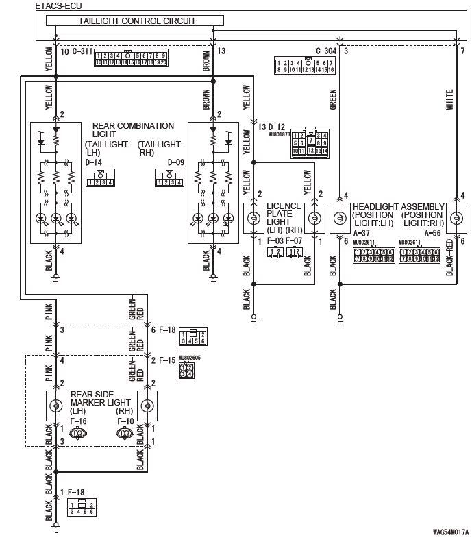
Inspection Procedure 9: One of the position lights, side marker lights or the license plate lights does not illuminate.
Position Lights, Licence Plate Lights and Rear Side Marker Lights Circuit
TECHNICAL DESCRIPTION (COMMENT)
When one of the position light, side marker light or license plate light does not illuminate, the harness, connector(s), or bulb(s) may have a problem, or the fuse may be burned out.
TROUBLESHOOTING HINTS
- Malfunction of bulbs
- Malfunction of rear combination light
- Malfunction of rear combination light harness
- Malfunction of license plate light
- Malfunction of headlight
- Malfunction of rear side maker light
- The wiring harness or connectors may have loose, corroded, or damaged terminals, or terminals pushed back in the connector
DIAGNOSIS
Required Special Tools:
- MB992006: Extra fine probe
- MB991223: Harness set
STEP 1. Rear combination light check.
Q: Does the rear combination light illuminate normally?
YES : Go to Step 2.
NO : Refer to P.54A.
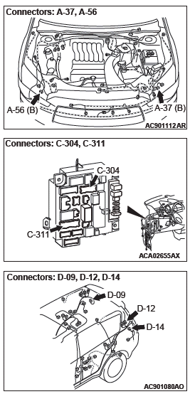
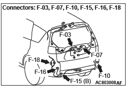
STEP 2. Check headlight assembly connector A-56 (position light:RH) or A-37 (position light:LH), license plate light connector F-07 (RH) or F-03 (LH), rear combination light connector D-14 (LH) or D-09 (RH), or rear side marker light connector F-10 (RH) or F-16 (LH) for loose, corroded or damaged terminals, or terminals pushed back in the connector.
Q: Is headlight assembly connector A-56 (position light:RH) or A-37 (position light:LH), license plate light connector F-07 (RH) or F-03 (LH), rear combination light connector D-14 (LH) or D-09 (RH), or rear side marker light connector F-10 (RH) or F-16 (LH) in good condition?
YES : Go to Step 3.
NO : Repair the damaged parts.
STEP 3. Bulb check.
Check the bulb(s) of the light that does not illuminate.
Q: Is the check result normal?
YES : Go to Step 4.
NO : Replace the bulb(s) of the light that does not illuminate.
STEP 4. Resistance measurement at headlight assembly connector A-56 (position light:RH) or A-37 (position light:LH), license plate light connector F-07 (RH) or F-03 (LH), rear combination light connector D-14 (LH) or D-09 (RH), or rear side marker light connector F-10 (RH) or F-16 (LH).
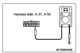
(1) Disconnect the connector, and measure at the wiring harness side.
(2) Measure the resistance between the connector of light which does not illuminate and the body ground.
- Measure the resistance between headlight assembly connector A-37 (position:LH), A-56 (position:RH) (terminal No. 6) and body ground.
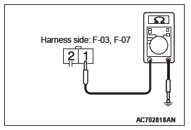
- Measure the resistance between license plate light connector F-03 (LH), F-07 (RH) (terminal No. 1) and body ground.
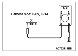
- Measure the resistance between rear combination light connector D-14 (LH), D-09 (RH) (terminal No. 4) and body ground.
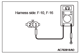
- Measure the resistance between rear side marker light
connector F-16 (LH), F-10 (RH) (terminal No. 1) and
body ground.
The measured value should be continuity exists (2 Ω or less).
Q: Does the measured resistance value correspond with this range?
YES : Go to Step 6.
NO : Go to Step 5.
STEP 5. Check wiring harness between headlight assembly connector A-56 (position light:RH) or A-37 (position light:LH) (terminal No. 6),license plate light connector F-07 (RH) or F-03 (LH) (terminal No. 1), rear combination light connector D-14 (LH) or D-09 (RH) (terminal No. 4), or rear side marker light connector F-10 (RH) or F-16 (LH) (terminal No. 1) and the body ground.
Check the ground wires for open circuit.
NOTE: Before the wiring harness check, check the intermediate connectors F-15 and F-18 <rear side marker light>, or and repair that if necessary.
Q: Is the wiring harness between headlight assembly connector A-56 (position light:RH) or A-37 (position light:LH) (terminal No. 6),license plate light connector F-07 (RH) or F-03 (LH) (terminal No. 1), rear combination light connector D-14 (LH) or D-09 (RH) (terminal No. 4), or rear side marker light connector F-10 (RH) or F-16 (LH) (terminal No. 1) and the body ground in good condition?
YES : Go to Step 8.
NO : Repair the wiring harness.
STEP 6. Check ETACS-ECU connector C-304 <headlight assembly> or C-311 <license plate light and rear side marker light> for loose, corroded or damaged terminals, or terminals pushed back in the connector.
Q: Is ETACS-ECU connector C-304 <headlight assembly> or C-311 <license plate light and rear side marker light> in good condition?
YES : Go to Step 7.
NO : Repair the damaged parts.
STEP 7. Check Wiring harness between headlight assembly connector A-56 (position light:RH) or A-37 (position light:LH) (terminal No. 4),license plate light connector F-07 (RH) or F-03 (LH) (terminal No. 2), rear combination light connector D-14 (LH) or D-09 (RH) (terminal No. 2), or rear side marker light connector F-10 (RH) or F-16 (LH) (terminal No. 2) and ETACS-ECU connector C-304 (terminal No. 7, 6) <headlight assembly>, C-311 (terminal No. 10, 13) <license plate light and rear side marker light>.
Check the output lines for open circuit.
NOTE: Before the wiring harness check, check the intermediate connectors D-12 <license plate light>, F-15 and F-18 <rear side marker light> and repair that if necessary.
Q: Is the wiring harness between headlight assembly connector A-56 (position light:RH) or A-37 (position light:LH) (terminal No. 4),license plate light connector F-07 (RH) or F-03 (LH) (terminal No. 2), rear combination light connector D-14 (LH) or D-09 (RH) (terminal No. 2), or rear side marker light connector F-10 (RH) or F-16 (LH) (terminal No. 2) and ETACS-ECU connector C-304 (terminal No. 7, 6) <headlight assembly>, C-311 (terminal No. 10, 13) <license plate light and rear side marker light> in good condition?
YES : Go to Step 8.
NO : Repair the wiring harness.
STEP 8. Retest the system.
Check that the position light, front side marker light, rear side marker light, or license plate light illuminate normally.
Q: Does the position light, front side marker light, rear side marker light, or license plate light work normally?
YES <The light illuminate normally at both high and low beams.> : The trouble can be an intermittent malfunction.
NO <When the position light does not illuminate> : Replace the position light socket.
NO <When the front side marker lights do not illuminate> : Replace the front side marker light socket.
NO <When the license plate light does not illuminate> : Replace the license plate light socket.
NO <When the rear side marker lights do not illuminate> : Replace the rear side maker light socket.
Inspection Procedure 10: The auto light function does not work normally.
CAUTION Whenever the ECU is replaced, ensure that the power supply circuit, the ground circuit and the communication circuit are normal.
OPERATION
The ETACS-ECU operates this function in accordance with the input signals from driving distance, lighting control sensor, and column switch (auto light switch). Also, when the column switch (lighting switch) is in the "AUTO" position, and when an abnormality is present to the auto light circuit, the fail-safe function is activated and the low beam is turned ON at all times regardless of the brightness around the vehicle.
TECHNICAL DESCRIPTION (COMMENT)
If the auto light function does not work normally, the above input signal circuit(s) or the ETACS-ECU may have a problem.
TROUBLESHOOTING HINTS
- Malfunction of the lighting control sensor
- Malfunction of the column switch
- Malfunction of the ETACS-ECU
- The wiring harness or connectors may have loose, corroded, or damaged terminals, or terminals pushed back in the connector
DIAGNOSIS
Required Special Tools:
- MB991958 Scan Tool (M.U.T.-III Sub Assembly)
- MB991824: Vehicle Communication Interface (V.C.I.)
- MB991827 M.U.T.-III USB Cable
- MB991910 M.U.T.-III Main Harness A (Vehicles with CAN communication system)
STEP 1. Using scan tool MB991958, diagnose the CAN bus line.
CAUTION To prevent damage to scan tool MB991958, always turn the ignition switch to the "LOCK" (OFF) position before connecting or disconnecting scan tool MB991958.
(1) Connect scan tool MB991958. Refer to "How to connect the Scan Tool (M.U.T.-III)".
(2) Turn the ignition switch to the "ON" position.
(3) Diagnose the CAN bus line.
(4) Turn the ignition switch to the "LOCK" (OFF) position.
Q: Is the CAN bus line found to be normal?
YES : Go to Step 2.
NO : Repair the CAN bus line.
STEP 2. Using scan tool MB991958, read the diagnostic trouble code.
Check if DTC is set to the LIN.
Q: Is the DTC set?
YES : Refer to DTC chart.
NO : Go to Step 3.
STEP 3. Using scan tool MB991958, read the ETACS diagnostic trouble code.
Check if DTC is set to the ETACS-ECU.
Q: Is the DTC set?
YES : Troubleshoot the ETACS.
NO : Go to Step 4.
STEP 4. Check that the headlights operate.
Check that the headlights (low-beam) illuminate normally.
Q: Is the check result normal?
YES : Go to Step 5.
NO : Refer to Inspection Procedure 1 "None of headlights (low-beam) illuminates".
STEP 5. Using scan tool MB991958, check data list.
Use the ETACS-ECU service data to check the signals related to the operation of auto light function.
- Turn the lighting switch to the "AUTO" position.
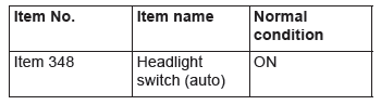
Q: Does scan tool MB991958 display the items "Headlight switch (auto)" as normal condition?
YES : Go to Step 6.
NO : Troubleshoot the ETACS-ECU. Refer to ETACS, Diagnosis.
STEP 6. Lighting control sensor check
Check the lighting control sensor.
Q: Is the check result normal?
YES : Go to Step 7.
NO : Replace the lighting control sensor.
STEP 7. Retest the system.
Check that the auto light function works normally.
Q: Is the check result normal?
YES : The trouble can be an intermittent malfunction.
NO : Replace the ETACS-ECU.
Inspection Procedure 10: None of turn-signal lights illuminates.
TECHNICAL DESCRIPTION (COMMENT)
If none of turn-signal lights illuminates, the ignition switch (IG1), the turn-signal light switch input circuit or the ETACS-ECU may have a problem.
TROUBLESHOOTING HINTS
- Malfunction of column switch
- Malfunction of the ETACS-ECU
- The wiring harness or connectors may have loose, corroded, or damaged terminals, or terminals pushed back in the connector
DIAGNOSIS
Required Special Tools:
- MB991958: Scan Tool (M.U.T.-III Sub Assembly)
- MB991824: Vehicle Communication Interface (V.C.I.)
- MB991827: M.U.T.-III USB Cable
- MB991910: M.U.T.-III Main Harness A (Vehicles with CAN communication system)
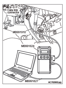
STEP 1. Using scan tool MB991958, read the ETACS-ECU diagnostic trouble code.
CAUTION To prevent damage to scan tool MB991958, always turn the ignition switch to the "LOCK" (OFF) position before connecting or disconnecting scan tool MB991958.
(1) Connect scan tool MB991958. Refer to "How to connect scan tool (M.U.T.-III)".
(2) Turn the ignition switch to the "ON" position.
(3) Check whether the ETACS-ECU DTC is set.
(4) Turn the ignition switch to the "LOCK" (OFF) position.
Q: Is the DTC set?
YES : Diagnose the ETACS-ECU.
NO : Go to Step 2.
STEP 2. Using scan tool MB991958, check data list.
Using the ETACS-ECU service data, check the signals related to the illumination of turn-signal light.
- Turn the ignition switch to the "ON" position.
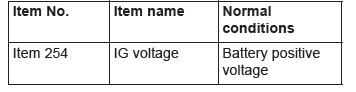
Q: Does scan tool MB991958 display the item "IG voltage" as normal condition?
YES : Go to Step 3.
NO : Troubleshoot the ETACS-ECU.
STEP 3. Retest the system.
Check that turn-signal lights illuminate.
Q: Do turn-signal lights work normally?
YES : The trouble can be an intermittent malfunction.
NO : Replace the ETACS-ECU.
Inspection Procedure 11: The comfort flashing function does not work normally.
TECHNICAL DESCRIPTION (COMMENT)
If the comfort flashing function does not work normally, the turn-signal light switch input circuit(s) and ETACS-ECU may have a problem.
TROUBLESHOOTING HINTS
- Malfunction of column switch
- Malfunction of the ETACS-ECU
- The wiring harness or connectors may have loose, corroded, or damaged terminals, or terminals pushed back in the connector
DIAGNOSIS
Required Special Tools:
- MB991958: Scan Tool (M.U.T.-III Sub Assembly)
- MB991824: Vehicle Communication Interface (V.C.I.)
- MB991827: M.U.T.-III USB Cable
- MB991910: M.U.T.-III Main Harness A (Vehicles with CAN communication system)
STEP 1. Using scan tool MB991958, Check the configuration function.
CAUTION To prevent damage to scan tool MB991958, always turn the ignition switch to the "LOCK" (OFF) position before connecting or disconnecting scan tool MB991958.
(1) Connect scan tool MB991958. Refer to "How to connect scan tool (M.U.T.-III)".
(2) Turn the ignition switch to the "ON" position.
(3) Use the ETACS-ECU configuration function to check that the "Comfort flasher" is set to "Enable".
(4) Turn the ignition switch to the "LOCK" (OFF) position.
Q: Is the "Comfort flasher" set to "Enable"?
YES : Go to Step 2.
NO : Use the ETACS-ECU customize function to set the "Comfort flasher" to "Enable".
STEP 2. Using scan tool MB991958, read the ETACS-ECU diagnostic trouble code.
(1) Turn the ignition switch to the "ON" position.
(2) Check whether the ETACS-ECU DTC is set.
(3) Turn the ignition switch to the "LOCK" (OFF) position.
Q: Is the DTC set?
YES : Diagnose the ETACS-ECU.
NO : Go to Step 3.
STEP 3. Check that the turn-signal light operate.
Check that the turn-signal light work normally when the ignition switch is in the "ON" position.
Q: Do turn-signal lights work normally?
YES : Go to Step 4.
NO : Refer to Inspection Procedure 10 "None of turn-signal lights illuminates".
STEP 4. Retest the system.
Check that the comfort flashing function works normally.
Q: Does comfort flashing function work normally?
YES : The trouble can be an intermittent malfunction.
NO : Replace the ETACS-ECU.
Inspection Procedure 12: The turn-signal indicator light do not illuminate.
CAUTION Whenever the ECU is replaced, ensure that the power supply circuit, the ground circuit and the communication circuit are normal.
TECHNICAL DESCRIPTION (COMMENT)
If the turn-signal light indicator does not illuminate normally, the harness in the CAN bus lin
READ NEXT:
 On-vehicle Service
HEADLIGHT AIMING
PRE-AIMING INSTRUCTIONS (LOW-BEAM)
1. Inspect for rusted or faulty headlight assemblies.
2. These conditions must be corrected before a satisfactory
adjustment can be made.
3. Insp
Local Interconnect Network (LIN)
General Information
LIN refers to "Local Interconnect Network," which is a
serial multiplex communication protocol* administrated
by LIN consortium. A communication circuit
employing the LIN protocol
SEE MORE:
Rear Wiper and Washer
REMOVAL AND INSTALLATION
Washer tank
Washer motor
Rear washer nozzle removal
steps
Liftgate spoiler
High-mounted stop light assembly
Rear washer nozzle assembly
Rear wiper blade removal steps
Rear wiper blade assembly
Rear wiper blade
Rear wiper motor removal steps
Cover
Rear wip
DTC C1035, C1041, C1042, C1043, C1044, C1046, C1047, C1048, C1049,
C104B, C104F, C1053, C1057, C105F, C1063, C1067, C105B, C1200, C1204, C1208,
C120C
DTC C1035 Mutual monitoring of RR wheel speed sensor
CAUTION
If there is any problem in the CAN bus lines, an incorrect
DTC may be set. Prior to this diagnosis, diagnose
the CAN bus lines (Refer to GROUP 54C − CAN Bus
Line Diagnostic Flow).
Whenever ECU is replaced, ensure that the CAN b
