Mitsubishi Outlander: Charging System
GENERAL INFORMATION
The charging system charges the battery with the generator output to keep the battery charged at a constant level during varying electrical load.
OPERATION
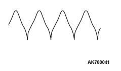
Rotation of the excited field coil generates AC voltage in the stator.
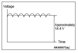
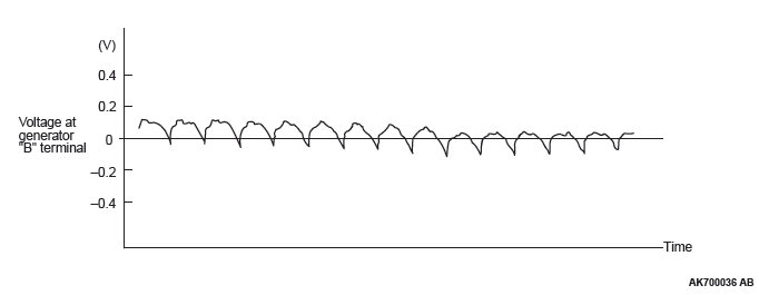
This alternating current is rectified through diodes to DC voltage having a waveform shown in the illustration above.
The average output voltage fluctuates slightly with the generator load condition.
When the ignition switch is turned on, current flows in the field coil and initial excitation of the field coil occurs.
When the stator coil begins to generate power after the engine is started, the field coil is excited by the output current of the stator coil.
The generator output voltage rises as the field current increases and it falls as the field current decreases. When the battery positive voltage (generator S terminal voltage) reaches a regulated voltage of approximately 14.4 V, the field current is cut off.
When the battery positive voltage drops below the regulated voltage, the voltage regulator regulates the output voltage to a constant level by controlling the field current.
In addition, when the field current is constant, the generator output voltage rises as the engine speed increases.
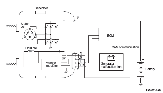
<2.4 L Engine>
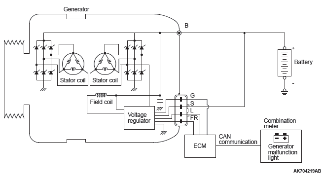
<3.0 L Engine>
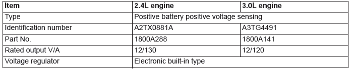
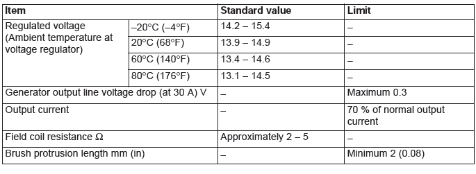
GENERAL SPECIFICATIONS
SERVICE SPECIFICATIONS
CHARGING SYSTEM DIAGNOSIS
TROUBLESHOOTING HINTS
Generator malfunction light does not go on when the ignition switch is turned to ON, before the engine starts.
- Check the generator malfunction light.
Generator malfunction light does not switch off after the engine starts.
- Check the IC voltage regulator inside the generator.
Discharged or overcharged battery.
- Check the IC voltage regulator inside the generator.
TROUBLESHOOTING GUIDE
The charging system troubleshooting guide is shown in the following steps.
STEP 1.
Q: Is the battery in good condition?
YES : Go to Step 2.
NO : Charge or replace the battery.
STEP 2.
Q: Is the generator drive belt in good condition?
YES : Go to Step 3.
NO : Adjust the belt tension or replace the belt.
STEP 3.
Q: Does the generator malfunction light come on when the ignition switch is turned on?
YES : Go to Step 4.
NO : Check the ignition switch. Check the generator malfunction light and its related circuits.
Check the generator.
STEP 4.
Q: Does the generator malfunction light go out after starting the engine?
YES : Go to Step 5.
NO : Check the generator
STEP 5.
Q: Is an oscilloscope available?
YES : Go to Step 6.
NO : Go to Step 7.
STEP 6.
Q: Does the oscilloscope show a normal wave pattern?
YES : Go to Step 7.
NO : Check the generator.
STEP 7.
- Engine: 2,500 r/min
- Headlight: ON (high beam)
- Voltage between generator terminal B and the positive battery terminal
OK: 0.5 V or less
- Voltage between the negative battery terminal and generator body
OK: 0.5 V or less
Q: Are the generator output line and ground line in good condition?
YES : Go to Step 8.
NO : Check the generator output line and ground line.
STEP 8.
Q: Is the output current normal?
YES : Go to Step 9.
NO : Check the generator.
STEP 9.
Q: Is the regulated voltage normal?
YES : Go to Step 10.
NO : Check the generator.
STEP 10.
Q: Is the voltage drop in the generator output line normal?
YES : Generator is normal. Check other systems.
NO : Check the output line.
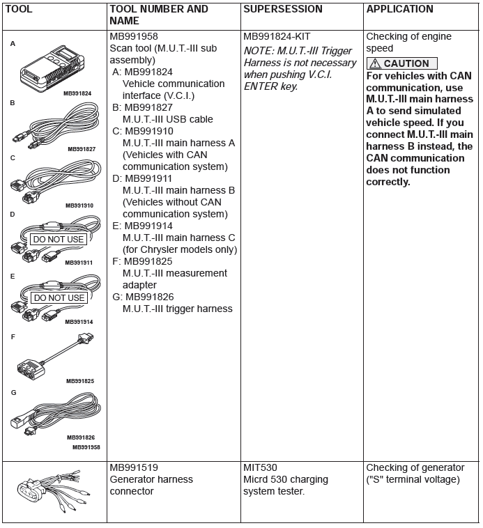
SPECIAL TOOL
ON-VEHICLE SERVICE
GENERATOR OUTPUT LINE VOLTAGE DROP TEST
Required Special Tool:
MB991958: Scan Tool (M.U.T.-III Sub Assembly)
- MB991824: V.C.I.
- MB991827: M.U.T.-III USB Cable
- MB991910: M.U.T.-III Main Harness A
This test determines whether the wiring from the generator "B" terminal to the positive battery terminal (including the fusible link) is in good condition or not:
WARNING
Battery posts, terminals and related accessories contain lead and lead compounds.
WASH HANDS AFTER HANDLING.
1. Always be sure to check the following before the test.
- Generator installation
- Generator drive belt tension
- Fusible link
- Abnormal noise from the generator while the engine is running.
2. Turn the ignition switch to the "LOCK" (OFF) position.
3. Disconnect the negative battery cable.
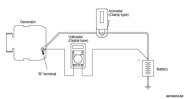
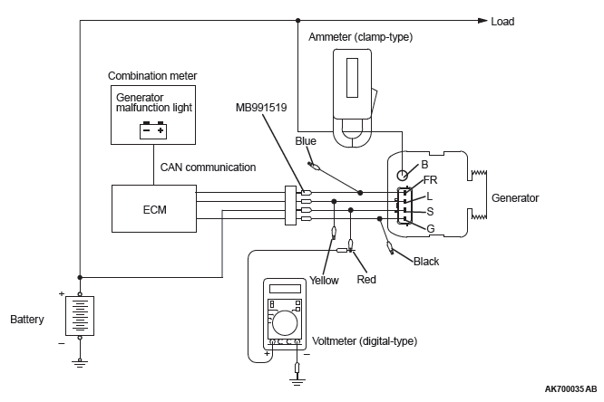
4. Connect a clamp-type DC test ammeter to the generator "B" terminal output wire.
NOTE: Disconnecting the generator output wire and connecting the ammeter may not thoroughly diagnose an alternator output line resistance increase problem because of an insufficient connection between terminal "B" and the output wire.
5. Connect a digital-type voltmeter between the generator "B" terminal and the positive battery terminal. (Connect the positive lead of the voltmeter to the "B" terminal, and then connect the negative lead of the voltmeter to the positive battery cable.)
6. Reconnect the negative battery cable.
7. Connect an engine tachometer or scan tool MB991958.
8. Leave the hood open.
9. Start the engine.
10.With the engine running at 2,500 r/min, turn the headlights and other lights on and off to adjust the generator load so that the value displayed on the ammeter is slightly above 30 A.
Read the voltmeter. Voltage reading at or below limit value means voltage drop between generator and battery is OK.
Limit value: maximum 0.3 V
NOTE: When the generator output is high and the value displayed on the ammeter does not decrease to 30 A, set the value to 40 A. Read the value displayed on the voltmeter at this time.
In this case the limit value becomes maximum 0.4 V.
Adjust the engine speed by gradually decreasing it until the value displayed on the ammeter is 30 A. Take a reading of the value displayed on the voltmeter at this time.
11.If the value displayed on the voltmeter is above the limit value, there is probably a malfunction in the generator output wire. Check the wiring between the generator "B" terminal and the positive battery terminal (including fusible link).
If a terminal is not sufficiently tight or if the harness has become discolored due to overheating, repair and then test again.
12.After the test, run the engine at idle.
13.Turn off all lights and turn the ignition switch to the "LOCK" (OFF) position.
NOTE: Vehicles for Canada, the headlight, taillight, etc. remain lit even when the lighting switch is in "OFF" position.
14.Disconnect the engine tachometer or scan tool MB991958.
15.Disconnect the negative battery cable.
16.Disconnect the ammeter and voltmeter.
17.Connect the negative battery cable.
18.Run the engine for 10 minutes at an idle.
OUTPUT CURRENT TEST
Required Special Tool:
MB991958: Scan Tool (M.U.T.-III Sub Assembly)
- MB991824: V.C.I.
- MB991827: M.U.T.-III USB Cable
- MB991910: M.U.T.-III Main Harness A
This test determines whether the generator outputs normal current. For best results, use a charging system tester. If not available, follow the steps below.
WARNING
Battery posts, terminals and related accessories contain lead and lead compounds.
WASH HANDS AFTER HANDLING.
1. Before the test, always be sure to check the following.
- Generator installation
- Battery
NOTE: The battery to be used should be slightly discharged. The load in a fully-charged battery will be insufficient and the test may not be able to be carried out correctly.
- Generator drive belt tension
- Fusible link
- Abnormal noise from the generator while the engine is running.
2. Turn the ignition switch to the "LOCK" (OFF) position.
3. Disconnect the negative battery cable.
4. Connect a clamp-type DC test ammeter to the generator "B" terminal output wire.
NOTE: Disconnecting the generator output wire and connecting the ammeter may not thoroughly diagnose an output current drop problem because of an insufficient connection between terminal "B" and the output wire.
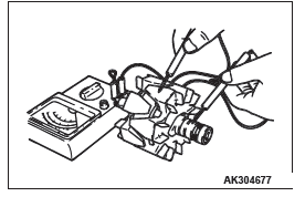
5. Connect a voltmeter with a range of 0 − 20 V between the generator "B" terminal and ground.
(Connect the positive lead of the voltmeter to the "B" terminal, and then connect the negative lead of the voltmeter to ground.)
6. Connect the negative battery cable.
7. Connect an engine tachometer or scan tool MB991958.
8. Leave the hood open.
9. Check to be sure that the reading on the voltmeter is equal to the battery positive voltage.
NOTE: If the voltage is 0 V, the cause is probably an open circuit in the wire or fusible link between the generator "B" terminal and the battery positive terminal or malfunctioning voltmeter.
10.After turning on the headlights, start the engine.
NOTE: Because the current from the battery will soon drop after the engine is started, step 11 should be carried out as quickly as possible in order to obtain the maximum current output value.
11.Immediately after setting the headlights to high beam and turning the heater blower switch to the highest position, increase the engine speed to 2,500 r/min and read the maximum current output value displayed on the ammeter.
Limit value: 70 % of nominal current output
NOTE: For the nominal current output, refer to the Generator Specifications.
NOTE: The current output value will depend on the electrical load and the temperature of the generator body.
NOTE: If the electrical load is small while testing, the specified level of current may not be output even though the generator is normal. In such cases, increase the electrical load by leaving the headlights turned on for some time to discharge the battery or by using the lighting system in another vehicle, and then test again.
NOTE: The specified level of current also may not be output if the temperature of the generator body or the ambient temperature is too high. In such cases, cool the generator and then test again.
12.The reading on the ammeter should be above the limit value. If the reading is below the limit value and the generator output wire is normal, remove the generator from the engine and check the generator.
13.Run the engine at idle speed after the test.
14.Turn the ignition switch to the "LOCK" (OFF) position.
15.Disconnect the engine tachometer or scan tool MB991958.
16.Disconnect the negative battery cable.
17.Disconnect the ammeter and voltmeter.
18.Connect the negative battery cable.
19.Run the engine for 10 minutes at an idle.
REGULATED VOLTAGE TEST
Required Special Tools:
- MB991958: Scan Tool (M.U.T.-III Sub Assembly)
- MB991824: V.C.I.
- MB991827: M.U.T.-III USB Cable
- MB991910: M.U.T.-III Main Harness A
- MB991519: Generator Harness Connector
This test determines whether the voltage regulator is correctly controlling the generator output voltage.
WARNING
Battery posts, terminals and related accessories contain lead and lead compounds.
WASH HANDS AFTER HANDLING.
1. Always be sure to check the following before the test:
- Generator installation
- Check to be sure that the battery installed in the vehicle is fully charged
- Generator drive belt tension
- Fusible link
- Abnormal noise from the generator while the engine is running
2. Turn the ignition switch to the "LOCK" (OFF) position.
3. Disconnect the negative battery cable.
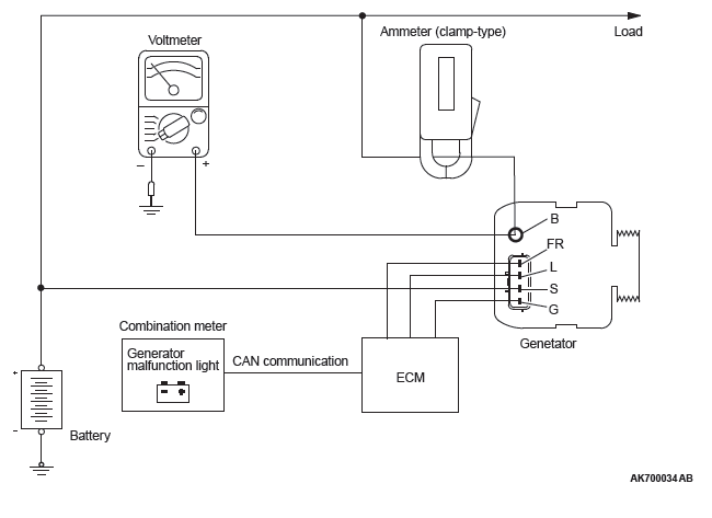
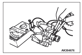
4. Use the special tool (Generator harness connector: MB991519) to connect a digital-type voltmeter between the generator "S" terminal and ground. (Connect the positive lead of the voltmeter to the "S" terminal, and then connect the negative lead of the voltmeter to a secure ground or to the negative battery terminal.)
5. Connect a clamp-type DC test ammeter to the generator "B" terminal output wire.
6. Reconnect the negative battery cable.
7. Connect an engine tachometer, or scan tool MB991958.
8. Turn the ignition switch to the "ON" position and check that the reading on the voltmeter is equal to the battery positive voltage.
NOTE: If the voltage is 0 V, the cause is probably an open circuit in the wire or fusible link between the generator "S" terminal and the battery positive terminal or malfunctioning voltmeter.
9. Check to be sure that all lights and accessories are off.
10.Start the engine.
NOTE: Do not drive the vehicle after the engine starts.
11.Increase the engine speed to 2,500 r/min.
12.Read the value displayed on the voltmeter when the current output by the generator becomes 15 A or less.
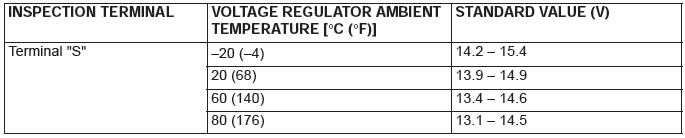
13.If the voltage reading conforms to the value in the voltage regulation table, then the voltage regulator is operating normally.
If the voltage is outside the standard value, there is a malfunction of the voltage regulator or the generator (Refer to the following table).
14.After the test, lower the engine speed to idle.
15.Turn the ignition switch to the "LOCK" (OFF) position.
16.Disconnect the engine tachometer or scan tool MB991958.
17.Disconnect the negative battery cable.
18.Disconnect the ammeter and voltmeter.
19.Remove the special tool (Generator harness connector: MB991519), and return the connector to the original condition.
20.Connect the negative battery cable.
21.Run the engine for 10 minutes at an idle.
VOLTAGE REGULATION TABLE
WAVE PATTERN CHECK USING AN OSCILLOSCOPE
MEASUREMENT METHOD
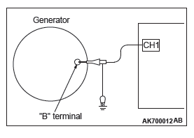
Connect the oscilloscope special patterns pick-up to the generator "B" terminal.
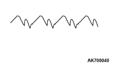
STANDARD WAVEFORM
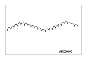
NOTE: The voltage waveform of the generator "B" terminal can undulate as shown at left. This waveform is produced when the regulator operates according to fluctuations in the generator load (current), and is normal for the generator.
If the ripple height is abnormally high (approximately 2 V or more during idling), the wires between the generator "B" terminal and the battery have broken due to fuse blowing, etc. The generator is usually operating properly.
ABNORMAL WAVEFORMS EXAMPLES
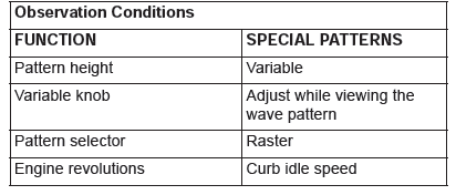
NOTE: The size of the waveform patterns can differ greatly, depending on the adjustment of the variable knob on the oscilloscope.
NOTE: Identification of abnormal waveforms is easier when there is a large output current (regulator is not operating).
(Waveforms can be observed when the headlights are illuminated.)
NOTE: Check the conditions of the generator malfunction light (illuminated/not illuminated) also, and carry out a total check.
ABNORMAL WAVEFORMS
- Example 1
PROBABLE CAUSE: Open circuit in diode
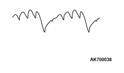
- Example 2
PROBABLE CAUSE: Short-circuit in diode
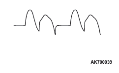
- Example 3
PROBABLE CAUSE: Open circuit in stator coil
- Example 4
PROBABLE CAUSE: Short-circuit in stator coil
GENERATOR ASSEMBLY
REMOVAL AND INSTALLATION <2.4L ENGINE>
Pre-removal operation
- Engine Room Under Cover Front A, B, C Removal
- Drive Belt Removal
Post-installation operation
- Drive Belt Installation
- Drive Belt Tension Check
- Engine Room Under Cover Front A, B, C Installation
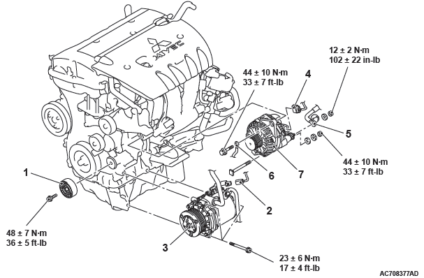
Removal steps
- Idler pulley
- A/C compressor connector connection
- A/C compressor assembly
- Generator connector connection
- Generator terminal connection
- Grounding cable connection
- Generator assembly
REMOVAL SERVICE POINTS
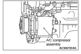
A/C COMPRESSOR ASSEMBLY REMOVAL
1. Remove the A/C compressor assembly from the A/C compressor bracket with the hose still attached.
2. Place the removed A/C compressor assembly where it will not be a hindrance when removing and installing the generator assembly, and secure it with a cord or wire.
GENERATOR ASSEMBLY REMOVAL
Move the A/C compressor assembly to one side, and then remove the generator assembly from under the vehicle.
INSTALLATION SERVICE POINTS
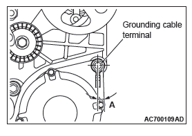
GROUNDING CABLE INSTALLATION
Install the grounding cable within the area marked with A in the illustration.
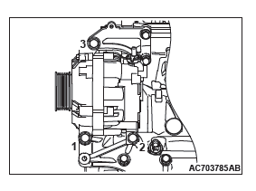
A/C COMPRESSOR ASSEMBLY INSTALLATION
1. Temporarily tighten the A/C compressor assembly to the A/C compressor bracket.
2. In accordance with the tightening order shown in the illustration, tighten the installation bolts for the A/C compressor bracket to the specified torque.
Tightening torque: 23 +- 6 N*m (17 +- 4 ft-lb)
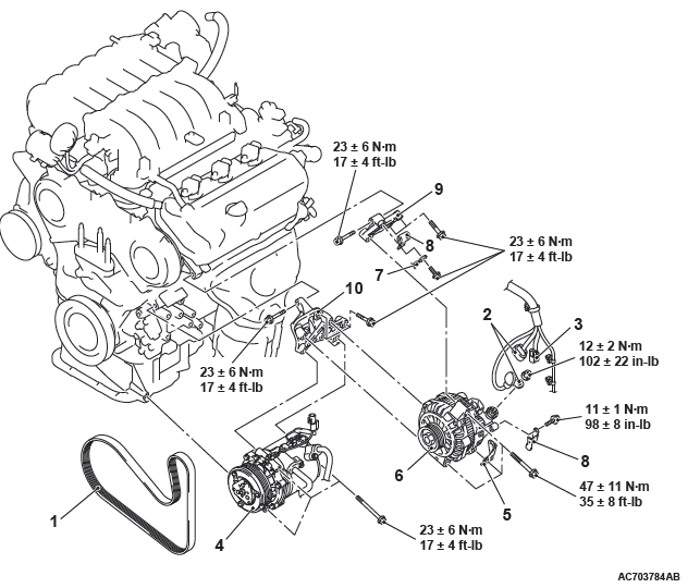
REMOVAL AND INSTALLATION <3.0L ENGINE>
Pre-removal operation
- Engine Room Under Cover Front Removal
Post-installation operation
- Generator Drive Belt Tension Check
- Engine Room Under Cover Front Installation
Removal steps
- Generator drive belt
- Generator connector and terminal connection
- A/C compressor connector connection
- A/C compressor assembly
- Harness bracket
- Generator assembly
- Grounding cable connection
- Harness bracket
- Generator upper bracket
- Generator lower bracket
REMOVAL SERVICE POINTS
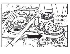
GENERATOR DRIVE BELT REMOVAL
CAUTION
When the generator drive belt is reused, draw an arrow indicating the rotating direction on the back of the belt using chalk to install the same direction.
1. Turn the drive belt auto-tensioner to counterclockwise, and insert the L-shaped hexagon wrench to the auto-tensioner hole in order to fix the auto-tensioner.
2. Remove the generator drive belt.
A/C COMPRESSOR ASSEMBLY REMOVAL
1. Remove the A/C compressor assembly from the A/C compressor bracket with the hose still attached.
2. Place the removed A/C compressor assembly where it will not be a hindrance when removing and installing the generator assembly, and secure it with a cord or wire.
GENERATOR ASSEMBLY REMOVAL
Move the A/C compressor assembly to one side, and then remove the generator assembly from under the vehicle.
INSTALLATION SERVICE POINT
GENERATOR ASSEMBLY INSTALLATION
1. Temporarily tighten the generator assembly to the generator bracket.
2. In accordance with the tightening order shown in the illustration, tighten the installation bolts for the generator bracket to the specified torque.
Tightening torque: 47 +- 11 N*m (35 +- 8 ft-lb)
DISASSEMBLY AND REASSEMBLY
<2.4L ENGINE>
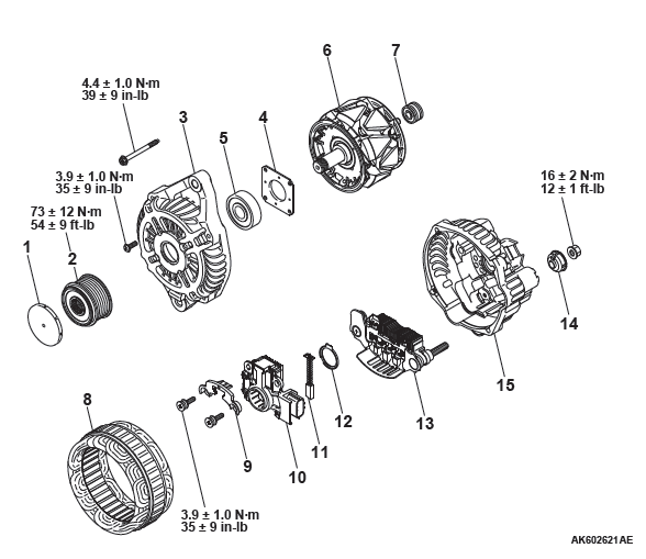
Disassembly steps
- Cap
- Pulley
- Front bracket
- Plate
- Front bearing
- Rotor
- Rear bearing
- Stator
- Plate
- Regulator assembly
- Brush
- Rubber packing
- Rectifier
- Insulator
- Rear bracket
<3.0L ENGINE>
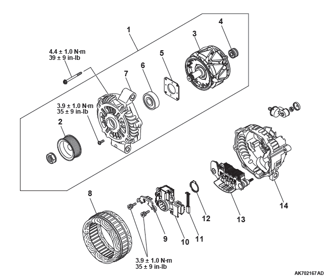
Disassembly steps
- Front bracket assembly
- Alternator pulley
- Rotor
- Rear bearing
- Bearing retainer
- Front bearing
- Front bracket
- Stator
- Plate
- Regulator assembly
- Brush
- Rubber packing
- Rectifier
- Rear bracket
DISASSEMBLY SERVICE POINTS
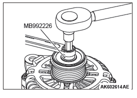
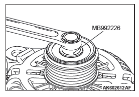
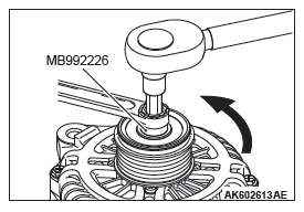
PULLEY REMOVAL<2.4L ENGINE>
1. Set the special tool Serration socket (MB992226) to the pulley.
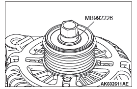
2. Set the closed wrench to the hexagonal area of the special tool Serration socket (MB992226).
3. Insert the hexagonal bit socket having width across flats of 10 mm into the hexagonal area of the rotor shaft.
4. Hold the pulley with the closed wrench. Rotate the rotor shaft clockwise to remove the pulley.
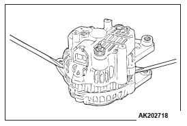
FRONT BRACKET REMOVAL<2.4L ENGINE>
CAUTION
Do not insert the screwdriver blades too deep. Doing so could damage the stator coil.
Insert the blades of screwdrivers between the front bracket and stator core, and pry and separate them with the screwdrivers.
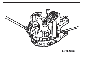
FRONT BRACKET ASSEMBLY REMOVAL<3.0L ENGINE>
CAUTION
Do not insert the screwdriver blades too deep. Doing so could damage the stator coil.
Insert the blades of screwdrivers between the front bracket assembly and stator core, and pry and separate them with the screwdrivers.
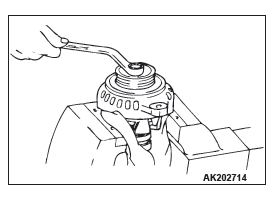
ALTERNATOR PULLEY REMOVAL<3.0L ENGINE>
CAUTION
Perform operation carefully not to damage the rotor.
Clamp the rotor in a vise with the pulley facing up to remove the pulley.
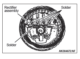
STATOR / REGULATOR ASSEMBLY REMOVAL
CAUTION
- Use a 180 − 250 W soldering iron, and finish unsoldering within four seconds. Diodes will be damaged by heat if unsoldering time is too long.
- Avoid applying undue force to the diode leads.
1. Unsolder the stator leads from the main diode of the rectifier assembly when the stator is removed.
2. When removing the rectifier assembly from the regulator assembly, undo the soldered points on the rectifier assembly.
REASSEMBLY SERVICE POINTS
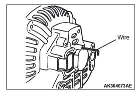
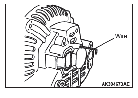
REGULATOR ASSEMBLY INSTALLATION
After installing the regulator assembly, insert a piece of wire through the hole in the rear bracket while pressing the brush to keep the brush against movement.
NOTE: Holding the brush with the wire facilities installation of the rotor.
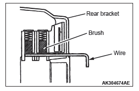
ROTOR INSTALLATION
Remove the brush holding wire after the rotor has been installed.
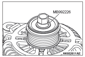
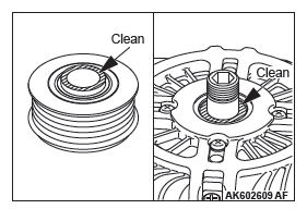
PULLEY INSTALLATION<2.4L ENGINE>
1. Clean the inner race of the front bearing and that of the pulley.
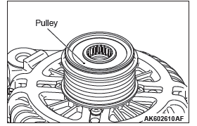
2. Screws the inner race of the pulley until it touches the inner race of the front bearing.
3. Set the special tool Serration socket (MB992226) to the pulley.
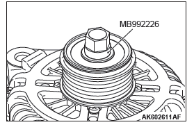
4. Set the closed wrench to the hexagonal area of the special tool Serration socket (MB992226).
5. Insert the hexagonal bit socket having width across flats of 10 mm into the hexagonal area of the rotor shaft.
6. Hold the pulley with the closed wrench.
Rotate the hexagonal bit socket counterclockwise to tighten it to the specified torque of 73 +- 12 N*m (54 +- 9 ft-lb).
INSPECTION
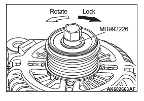
PULLEY<2.4L ENGINE>
Lock the pulley when rotating it clockwise. Check that the pulley rotates smoothly when rotating it counterclockwise.
CAUTION
Locking the one-way clutch might cause the damaged drive belt and an abnormal noise.
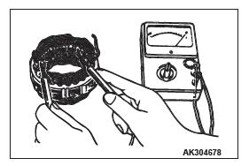
ROTOR
1. Measure the resistance between the two slip rings of the rotor coil to check the continuity between them.
Replace the rotor if the resistance is not within the standard value range.
Standard value: 2.1 − 2.4 Ω
2. Check the continuity between the slip rings and core.
3. If continuity is present, replace the rotor.
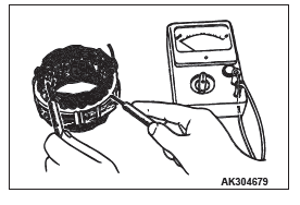
STATOR
1. Check the continuity between coil leads.
If there is no continuity, replace the stator.
2. Check the continuity between coil and core.
If there is continuity, replace the stator.
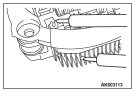
RECTIFIER ASSEMBLY
1. Check the condition of the (+) heat sink by checking the continuity between the (+) heat sink and each of the stator coil lead connecting terminals.
If the continuity is present for both terminals, or if no continuity is present for both terminals, the diode is shorted.
Replace the rectifier assembly.
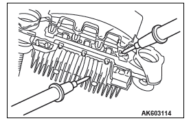
2. Check the condition of the (−) heat sink by checking the continuity between the (−) heat sink and each of the stator coil lead connecting terminals.
If the continuity is present for both terminals, or if no continuity is present for both terminals, the diode is shorted.
Replace the rectifier assembly.
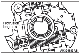
BRUSH
1. Measure the length of the protrusion of the brush. Replace the brush if the protrusion length is shorter than the limit.
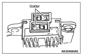
Limit: 2 mm (0.08 inch) minimum 2. Unsolder the lead of the brush. The brush will come out, becoming ready for removal.
3. Install a new brush by pushing it into the holder as shown in the drawing and soldering the lead.
READ NEXT:
 Starting System
GENERAL INFORMATION
If the ignition switch is turned to the "START" position,
current flows in the coil provided inside magnetic
switch, attracting the plunger. When the plunger
is attracted, the lev
Ignition System
GENERAL INFORMATION
This system is equipped with four <2.4L> or six
<3.0L> ignition coils with built-in power transistors for
each of the cylinders.
Interruption of the primary current fl
SEE MORE:
DTC P0010, P0011, P0013, P0014, P0016, P0017, P0031, P0032, P0037, P0038
DTC P0010: Intake Engine Oil Control Valve Circuit
CIRCUIT OPERATION
The intake engine oil control valve power is supplied
from the MFI relay (terminal No. 2).
The ECM controls ground intake engine oil control
valve by turning the power transistor in the
ECM "ON" and "OFF".
TECHNICAL DESCR
Oil Pan
REMOVAL AND INSTALLATION
Pre-removal operation
Engine Room Under Cover Front B and Engine Room
Side Cover (RH) Removal
Engine Oil Draining
Drive Belt Removal
Post-installation operation
Drive Belt Installation
Engine Oil Refilling
Engine Room Under Cover Front B and Engine Room
Side
