Mitsubishi Outlander: Starting System
GENERAL INFORMATION
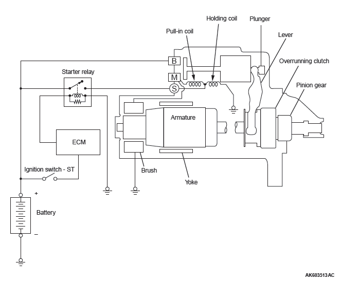
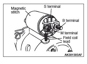
If the ignition switch is turned to the "START" position, current flows in the coil provided inside magnetic switch, attracting the plunger. When the plunger is attracted, the lever connected to the plunger is actuated to engage the starter clutch.
On the other hand, attracting the plunger will turn on the magnetic switch, allowing the "B" terminal and "M" terminal to conduct. Thus, current flows to engage the starter motor.
When the ignition switch is returned to the "ON" position after starting the engine, the starter clutch is disengaged from the ring gear.
An overrunning clutch is provided between the pinion and the armature shaft, to prevent damage to the starter.
OPERATION
For models equipped with A/T, when the ignition switch is turned to the "ST" position while the selector lever is at the "P" or "N" position, the contact (magnetic switch) of the starter is switched ON and the starter motor is activated.
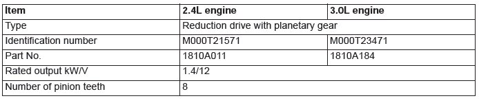
GENERAL SPECIFICATIONS
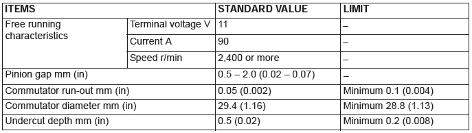
SERVICE SPECIFICATIONS
STARTING SYSTEM DIAGNOSIS
TROUBLESHOOTING HINTS
The starter motor does not operate at all.
WARNING
Battery posts, terminals and related accessories contain lead and lead compounds. WASH HANDS AFTER HANDLING.
- Check the starter (coil).
- Check for poor contact at the battery terminals and starter.
- Check the transmission range switch.
The starter motor doesn't stop
- Check the starter (magnetic switch).
TROUBLESHOOTING GUIDE
The starting system troubleshooting guide is shown in the following steps.
WARNING
Battery posts, terminals and related accessories contain lead and lead compounds. WASH HANDS AFTER HANDLING.
STEP 1.
Q: Is the battery in good condition?
YES : Go to Step 2.
NO : Charge or replace the battery.
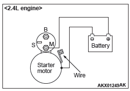
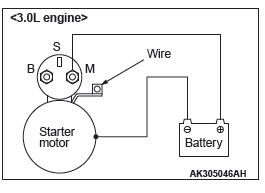
STEP 2.
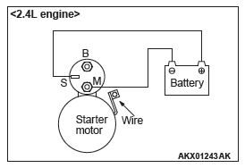
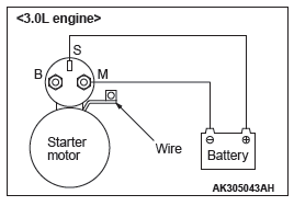
- Disconnect the starter motor S (solenoid) terminal connector.
- Using a jumper wire, apply battery positive voltage to the starter motor S (solenoid) terminal.
- Check the engine condition.
OK: Turns normally
Q: Dose the starter motor operate normally?
YES :
- Check the ignition switch
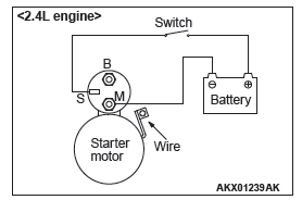
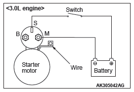
- Check the transmission range switch. <2.4L>, <3.0L>
- Check the line between the battery and starter motor S (solenoid) terminal.
NO : Go to Step 3.
STEP 3.
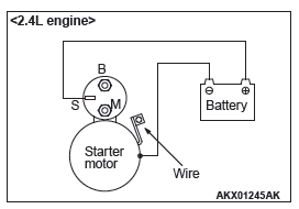
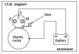
- Check the cable between starter B (battery) terminal and battery positive terminal for connection and continuity.
Q: Is the starter cable in good condition?
YES : Go to Step 4.
NO : Repair or replace the cable.
STEP 4.
- Check the connection and the continuity of the cable between the starter motor body and the negative battery terminal.
Q: Is the ground line in good condition?
YES : Go to Step 5.
NO : Repair or replace the cable.
STEP 5.
Q: Is the starter motor in good condition?
YES : Excessive rotational resistance of the engine.
NO : Replace the starter motor.
ON-VEHICLE SERVICE
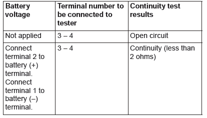
STARTER RELAY CHECK
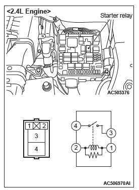
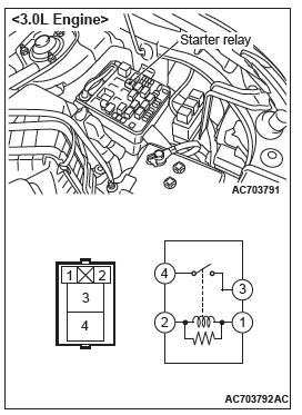
STARTER MOTOR ASSEMBLY INSPECTION
REMOVAL AND INSTALLATION <2.4L ENGINE>
Pre-removal operation
- Air Cleaner Intake Duct and Air Cleaner Intake Hose Removal
- Battery and Battery Tray Removal
- Engine Room Under Cover Front A, B Removal
Post-installation operation
- Engine Room Under Cover Front A, B Installation
- Battery and Battery Tray Installation
- Air Cleaner Intake Duct and Air Cleaner Intake Hose Installation
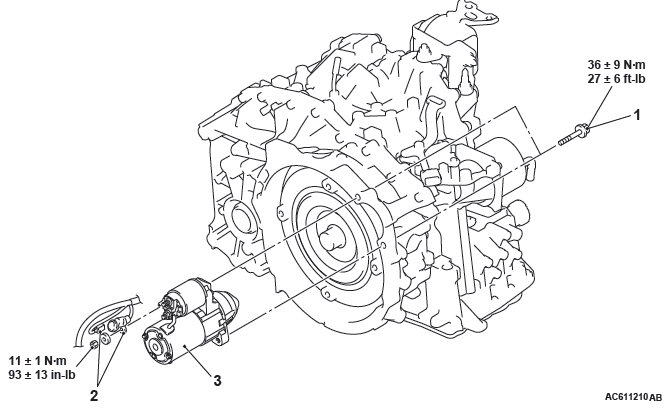
Removal steps
- Emission vacuum hose and brake booster vacuum hose connection
- Throttle body stay
- Starter mounting bolts
- Starter connector and terminal connection
- Starter assembly
REMOVAL SERVICE POINT
STARTER CONNECTOR AND TERMINAL/ STARTER ASSEMBLY REMOVAL
1. Slide the starter assembly, and disconnect the starter connector and terminal.
2. Remove the starter assembly from the lower front of the engine.
REMOVAL AND INSTALLATION <3.0L ENGINE>
Pre-removal and Post-installation Operation
- Engine Room Under Cover Front Removal and Installation
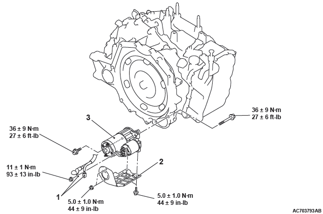
Removal steps
- Starter connector and terminal connection
- Starter cover
- Starter assembly
REMOVAL SERVICE POINT
STARTER ASSEMBLY REMOVAL
Remove the starter assembly from under the vehicle.
INSPECTION
PINION GAP ADJUSTMENT
1. Disconnect the lead wire from the M-terminal of the magnetic switch.
2. Connect a 12-volt battery between the S-terminal and M-terminal.
CAUTION
This test must be performed quickly (in less than 10 seconds) to prevent the coil from burning.
3. Set the switch to "ON", and the pinion will move out.
4. Check the pinion-to-stopper clearance (pinion gap) with a feeler gauge.
Standard value: 0.5 − 2.0 mm (0.02 − 0.07 inch)
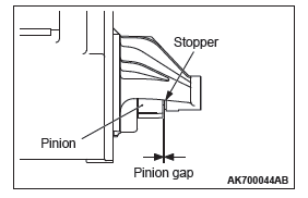
5. If the pinion gap is out of specification, adjust by adding or removing gasket(s) between the magnetic switch and front bracket.
MAGNETIC SWITCH PULL-IN TEST
1. Disconnect the field coil wire from the M-terminal of the magnetic switch.
CAUTION
This test must be performed quickly (in less than 10 seconds) to prevent the coil from burning.
2. Connect a 12-volt battery between the S-terminal and M-terminal.
3. If the pinion moves out, the pull-in coil is good. If it doesn't, replace the magnetic switch.
MAGNETIC SWITCH HOLD-IN TEST
1. Disconnect the field coil wire from the M-terminal of the magnetic switch.
CAUTION
This test must be performed quickly (in less than 10 seconds) to prevent the coil from burning.
2. Connect a 12-volt battery between the S-terminal and body.
3. Manually pull out the pinion as far as the pinion stopper position.
4. If the pinion remains out, everything is operating properly. If the pinion moves in, the hold-in circuit is open. Replace the magnetic switch.
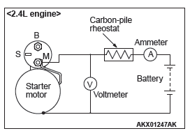
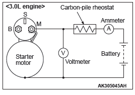
FREE RUNNING TEST
1. Place the starter motor in a vise equipped with soft jaws and connect a fully-charged 12-volt battery to the starter motor as follows:
2. Connect a test ammeter (100-ampere scale) and carbon pile rheostat in series between the positive battery terminal and starter motor terminal.
3. Connect a voltmeter (15-volt scale) across the starter motor.
4. Rotate carbon pile to full-resistance position.
5. Connect the battery cable from the negative battery terminal to the starter motor body.
6. Adjust the rheostat until the battery positive voltage shown by the voltmeter is 11 V.
7. Confirm that the maximum amperage is within the specifications and that the starter motor turns smoothly and freely.
Current: maximum 90 Amps
MAGNETIC SWITCH RETURN TEST
1. Disconnect the field coil wire from the M-terminal of the magnetic switch.
CAUTION
This test must be performed quickly (in less than 10 seconds) to prevent the coil from burning.
2. Connect a 12-volt battery between the M-terminal and body.
WARNING
Be careful not to get your fingers caught when pulling out the pinion.
3. Pull the pinion out and release. If the pinion quickly returns to its original position, everything is operating properly. If it doesn't, replace the magnetic switch.
DISASSEMBLY AND REASSEMBLY
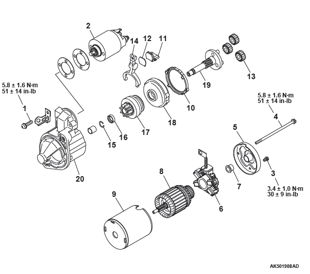
Disassembly steps
- Screw
- Magnetic switch
- Screw
- Bolt
- Rear bracket
- Brush holder
- Rear bearing
- Armature
- Yoke assembly
- Packing A
- Packing B
- Plate
- Planetary gear
- Lever
- Snap ring
- Stop ring
- Overrunning clutch
- Internal gear
- Planetary gear shaft
- Front bracket
DISASSEMBLY SERVICE POINTS
MAGNETIC SWITCH REMOVAL
CAUTION
Do not clamp the yoke assembly with a vise.
Disconnect the lead from the M terminal of the magnetic switch.
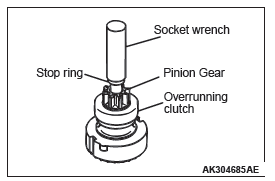
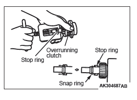
SNAP RING/STOP RING REMOVAL
1. Apply a long socket wrench of an appropriate size to the stop ring and strike the wrench to drive out the stop ring toward the pinion gear side.
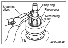
2. Remove the snap ring with snap ring pliers, then remove the stop ring and overrunning clutch.
STARTER MOTOR PARTS CLEANING
1. Never clean in a solvent such starter motor parts as the magnetic switch, brush holder, and armature. If they are soaked in a solvent, their insulation could be impaired.
When these parts require cleaning, wipe off contamination with cloth.
2. Never soak the drive unit in a solvent. If it is washed in a solvent, the grease having been packed in the overrunning clutch at the factory will be washed out. Wipe the drive unit with cloth if it requires cleaning.
REASSEMBLY SERVICE POINTS
STOP RING/SNAP RING INSTALLATION
Use a suitable puller to pull the stop ring until it gets over the snap ring.
INSPECTION
COMMUTATOR
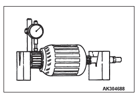
1. Support the armature with a pair of V block and turn it to measure the runout of the surface not rubbed by the brushes using a dial gauge.
Standard value: 0.05 mm (0.002 inch) or less
Limit: 0.1 mm (0.004 inch)
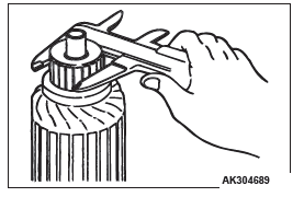
2. Measure the diameter of the commutator.
Standard value: 29.4 mm (1.157 inch)
Limit: 28.8 mm (1.134 inch)
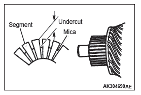
3. Measure the depth of the undercut between segments.
Standard value: 0.5 mm (0.002 inch)
Limit: 0.2 mm (0.008 inch)
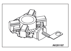
BRUSH HOLDER
Push the brush into the brush holder to make sure that the spring is working on the brush.
If the spring is not working, replace the brush holder.
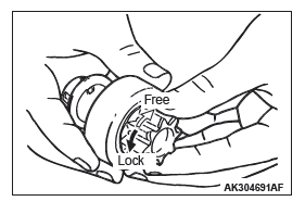
OVERRUNNING CLUTCH
1. Make sure that the pinion cannot be turned counterclockwise and can be turned clockwise freely.
2. Check the pinion for abnormal ware and damage.
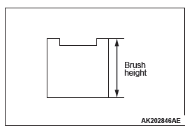
BRUSHES
1. Check the commutator contacting surface of each brush for abnormal roughness. Also check the height of the brush.
Replace the brush holder if the height is lower than the limit.
Limit: 7.0 mm (0.28 inch)
2. When the contact surface of the brush is rectified or the brush holder is replaced, recondition the contact surface with sandpaper wrapped around the commutator.
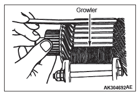
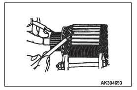
ARMATURE COIL
1. Check the armature coil for short circuit as follows.
2. Set the armature in a growler.
CAUTION
Clean the surface of the armature thoroughly before performing the test.
3. While holding a thin strip of iron against the armature in parallel with its axis, turn the armature slowly. The armature is normal if the iron strip is not attracted to the armature or it does not vibrate.
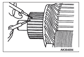
4. Check the insulation between commutator segments and armature coils. The armature coils are properly insulated if no continuity is present.
5. Check continuity between a segment and another. There is no open circuit in the tested coil if there is continuity.
READ NEXT:
 Ignition System
GENERAL INFORMATION
This system is equipped with four <2.4L> or six
<3.0L> ignition coils with built-in power transistors for
each of the cylinders.
Interruption of the primary current fl
Engine Control
GENERAL INFORMATION
For the accelerator system, the electronic throttle
valve control system, disposing of the accelerator
cable, is adopted.
This system determines the amount of pressure
applied to
SEE MORE:
Water Hose and Water Pipe
REMOVAL AND INSTALLATION <2.4L ENGINE>
Pre-removal Operation
Engine Coolant Draining
Engine Upper Cover Removal
Air Cleaner Assembly Removal
Thermostat Removal
Post-installation Operation
Thermostat Installation
Air Cleaner Assembly Installation
Engine Upper Cover Installation
En
Active Stability Control System (ASC)
Service Specifications
Diagnosis
INTRODUCTION TO ASC DIAGNOSIS
The active stability control system (ASC) operates
differently from conventional brake systems. These
differences include sounds, sensations, and vehicle
performance that owners and service technicians
who are not familiar with ASC may
