Mitsubishi Outlander: DTC B1B54, B1B55, B1B56, B1B70, B1B71, B1B72, B1B73, B1B75, B1B76, B1BA3, B1BA4, B1BA5, B1BAA, B1BC7, B1BCF
DTC B1B54: Seat Belt Buckle Switch (RH) Circuit (Ground Side) Shorted
DTC B1B55: Seat Belt Buckle Switch (RH) Circuit (Power Supply Side) Shorted
DTC B1B56: Seat Belt Buckle Switch (RH) Circuit Open
CAUTION If DTC B1B54, B1B55 or B1B56 are set in the SRS-ECU, always diagnose the CAN main bus lines.
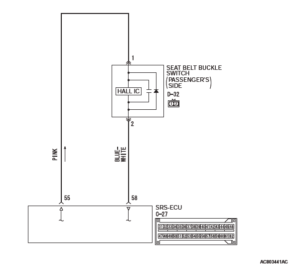
CIRCUIT OPERATION
The SRS-ECU determines whether the seat belt is fastened or not according to the connection location of the seat belt buckle switch in the seat buckle.
DTC SET CONDITIONS
The DTC is set when the seat belt buckle switch output current is not within the specified range.
TROUBLESHOOTING HINTS
- Malfunction of the seat belt buckle switch
- Damaged wiring harnesses or connectors
- Malfunction of the SRS-ECU
DIAGNOSIS
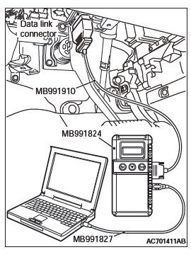
Required Special Tools:
- MB991222: Probe
- MB991958: Scan Tool (M.U.T.-III Sub Assembly)
- MB991824: Vehicle Communication Interface (V.C.I.)
- MB991827: M.U.T.-III USB Cable
- MB991910: M.U.T.-III Main Harness A (Vehicles with CAN communication system)
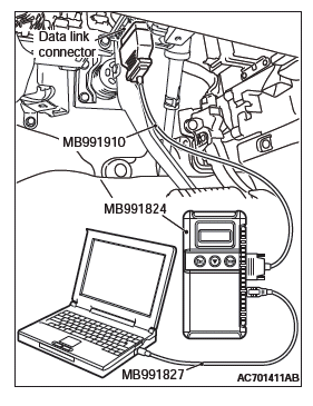
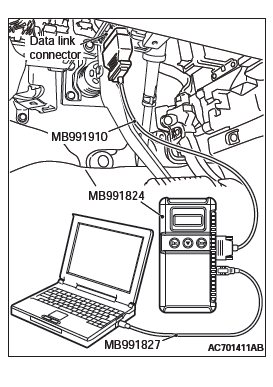
STEP 1. Using scan tool MB991958, diagnose the CAN bus line.
CAUTION To prevent damage to scan tool MB991958, always turn the ignition switch to the "LOCK" (OFF) position before connecting or disconnecting scan tool MB991958.
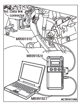
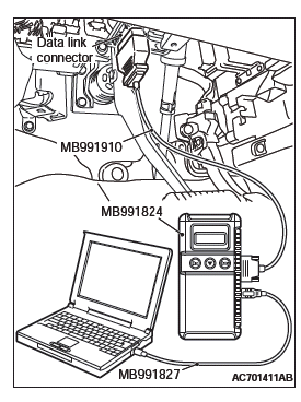
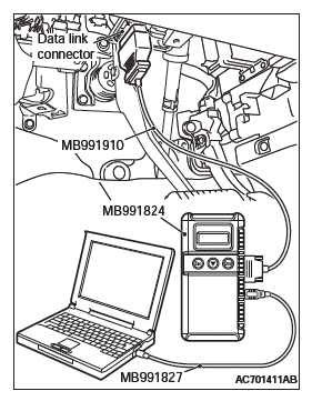
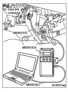
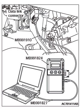
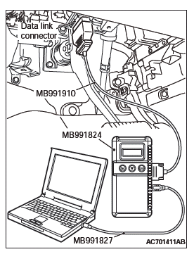
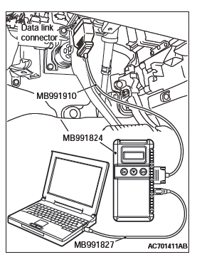
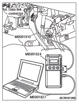
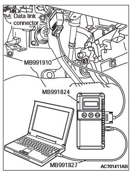
- Connect scan tool MB991958. Refer to "How to connect the scan tool".
- Connect scan tool MB991958 to the data link connector.
- Turn the ignition switch to the "ON" position.
- Diagnose the CAN bus line.
- Turn the ignition switch to the "LOCK" (OFF) position.
Q: Is the CAN bus line found to be normal?
YES : Go to Step 2.
NO : Repair the CAN bus line (Refer to GROUP 54C, Diagnosis).
STEP 2. Recheck for diagnostic trouble code.
Check again if the DTC is set.
- Erase the DTC.
- Turn the ignition switch to "ON" position.
- Check if the DTC is set.
- Turn the ignition switch to the "LOCK" (OFF) position.
Q: Is the DTC set?
YES : Go to Step 3.
NO : There is an intermittent malfunction such as poor engaged connector(s) or open circuit (Refer to GROUP 00, How to Cope with Intermittent Malfunction).
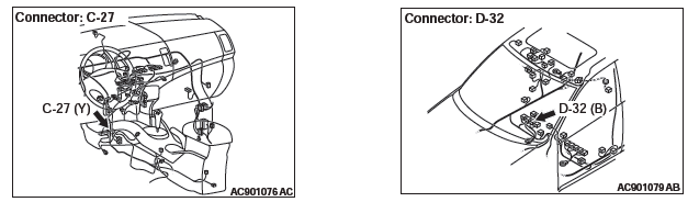
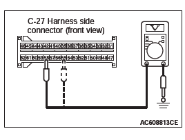
STEP 3. Check the harness short circuit between seat belt buckle switch (passenger's side) connector D-32 and the SRS-ECU connector C-27.
- Disconnect the negative battery terminal.
- Disconnect passenger's seat belt buckle switch connector D-32.
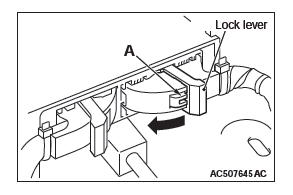
- While pushing the part "A" indicated in the figure of the harness side connector, turn the lock lever to the direction of the arrow to release the lock lever, and disconnect the C-27 SRS-ECU connector.
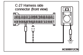
- Measure the resistance between terminal 55, 58 and body
ground (DTC B1B54 only).
It should be an open circuit.
- Connect the negative battery terminal.
- Ignition switch: ON.
- Measure the voltage between terminal 55, 58 and body
ground (No. B1B55 only).
Voltage should measure 1 volt or less.
Q: Is the check result normal?
YES : Go to Step 5.
NO : Go to Step 4.
STEP 4. Check the harness wires between SRS-ECU connector C-27 (terminal No.55 and 58) and the passenger's seat belt buckle switch connector D-32 (terminal No.1 and 2).
Q: Is the check result normal?
YES : Go to Step 6.
NO : Repair the harness wires between SRS-ECU connector C-27 and the passenger's seat belt buckle switch connector D-32. Then go to Step 6.
STEP 5. Check the harness wires between SRS-ECU connector C-27 (terminal No.55 and 58) and the passenger's seat belt buckle switch connector D-32 (terminal No.1 and 2).
- Disconnect the negative battery terminal.
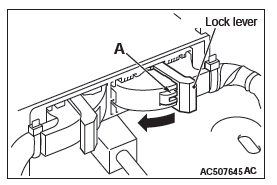
- While pushing the part "A" indicated in the figure of the harness side connector, turn the lock lever to the direction of the arrow to release the lock lever, and disconnect the C-27 SRS-ECU connector.
- Disconnect the passenger's seat belt buckle switch connector D-32.
CAUTION Do not insert a probe into the terminal from D-32 harness side connector front side directly, as the connector contact pressure may be weakened.
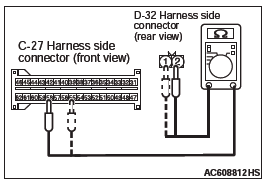
- Check for continuity between the following terminals. It should be less than 2 ohms <No.B1B56>.
- SRS-ECU connector C-27 (terminal No.55) and the passenger's seat belt buckle switch connector D-32 (terminal No.1)
- SRS-ECU connector C-27 (terminal No.58) and the passenger's seat belt buckle switch connector D-32 (terminal No.2)
Q: Is the check result normal?
YES : go to Step 6.
NO : Repair harness wires between SRS-ECU connector C-27 and the passenger's seat belt buckle switch connector D-32.
STEP 6. The passenger's seat belt buckle switch check.
Q: Is the check result normal?
YES : Go to Step 7.
NO : Replace the passenger's seat belt buckle switch.
STEP 7. Recheck for diagnostic trouble code.
Check again if the DTC is set.
- Erase the DTC.
- Turn the ignition switch to the "ON" position.
- Check if the DTC is set.
- Turn the ignition switch to the "LOCK" (OFF) position.
Q: Is DTC B1B54, B1B55 or B1B56 set?
YES : Replace the SRS-ECU.
NO : The procedure is complete.
DTC B1B70: Malfunction of G-sensor inside Front Impact Sensor (LH)
DTC B1B71: Malfunction of G-sensor inside Front Impact Sensor (RH)
CAUTION If DTC B1B70 or B1B71 is set in the SRS-ECU, always diagnose the CAN main bus line.
DTC SET CONDITIONS
These DTCs are set if the following conditions are detected from the analog G-sensor inside the front impact sensor output:
- Analog G-sensor is not operating.
- Analog G-sensor characteristics are abnormal.
- Analog G-sensor output is abnormal.
TROUBLESHOOTING HINTS
Malfunction of front impact sensor (LH) (for DTC B1B70) and front impact sensor (RH) (for DTC B1B71)
DIAGNOSIS
Required Special Tool:
- MB991958: Scan Tool (M.U.T.-III Sub Assembly)
- MB991824: Vehicle Communication Interface (V.C.I.)
- MB991827: M.U.T.-III USB Cable
- MB991910: M.U.T.-III Main Harness A (Vehicles with CAN communication system)
STEP 1. Using scan tool MB991958, diagnose the CAN bus line.
CAUTION To prevent damage to scan tool MB991958, always turn the ignition switch to the "LOCK" (OFF) position before connecting or disconnecting scan tool MB991958.
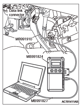
- Connect scan tool MB991958. Refer to "How to connect the scan tool".
- Turn the ignition switch to the "ON" position.
- Diagnose the CAN bus line.
- Turn the ignition switch to the "LOCK" (OFF) position.
Q: Is the CAN bus line found to be normal?
YES : Go to Step 2.
NO : Repair the CAN bus line (Refer to GROUP 54C, Diagnosis).
STEP 2. Check the front impact sensor. (Using scan tool MB991958, read the diagnostic trouble code.)
- Disconnect the negative battery terminal.
- A front impact sensor is checked in the following way.
- Replace the front impact sensor (LH) {In case of code B1B70 (Regardless of "Active" or "Stored" faults) } with new part.
- Replace the front impact sensor (RH) {In case of code B1B71 (Regardless of "Active" or "Stored" faults) } with new part.
- Connect the negative battery terminal.
- After erasing the diagnostic trouble code memory, check the diagnostic trouble code again.
Q: Is either DTC B1B70 or B1B71 set?
YES : Go to Step 3.
NO : The procedure is complete.
STEP 3. Check the SRS-ECU (Using scan tool MB991958, read the diagnostic trouble code.)
- Disconnect the negative battery terminal.
- Replace the SRS-ECU with a new one.
- Connect the negative battery terminal.
- Check the diagnostic trouble code again.
Q: Is either DTC B1B70 or B1B71 set?
YES : Return to Step 1.
NO : The procedure is complete.
DTC B1B72: Malfunction of G-sensor Inside Side Impact Sensor (Front) (LH)
DTC B1B75: Malfunction of G-sensor Inside Side Impact Sensor (Front) (RH)
CAUTION If the diagnostic trouble code B1B72 or B1B75 is set in the SRS-ECU, always diagnose the CAN main bus line.
DTC SET CONDITIONS
These DTCs are set if the following conditions are detected from the analog G-sensor inside the side impact sensor output:
- Analog G-sensor is not operating.
- Analog G-sensor characteristics are abnormal.
- Analog G-sensor output is abnormal.
TROUBLESHOOTING HINTS
Malfunction of side impact sensor (front) (LH) (for DTC B1B72) and side impact sensor (front) (RH) (for DTC B1B75)
DIAGNOSTIC PROCEDURE
Required Special Tools:
- MB991958: Scan Tool (M.U.T.-III Sub Assembly)
- MB991824: Vehicle Communication Interface (V.C.I.)
- MB991827: M.U.T.-III USB Cable
- MB991910: M.U.T.-III Main Harness A (Vehicles with CAN communication system)
STEP 1. Using scan tool MB991958, diagnose the CAN bus line.
CAUTION To prevent damage to scan tool MB991958, always turn the ignition switch to the "LOCK" (OFF) position before connecting or disconnecting scan tool MB991958.
- Connect scan tool MB991958. Refer to "How to connect the scan tool".
- Turn the ignition switch to the "ON" position.
- Diagnose the CAN bus line.
- Turn the ignition switch to the "LOCK" (OFF) position.
Q: Is the CAN bus line found to be normal?
YES : Go to Step 2.
NO : Repair the CAN bus line (Refer to GROUP 54C, Diagnosis).
STEP 2. Check the side impact sensor. (Using scan tool MB991958, read the diagnostic trouble code.)
- Disconnect the negative battery terminal.
- A side impact sensor is checked in the following way.
- Replace the side impact sensor (front) (LH) {In case of code B1B72 (Regardless of "Active" or "Stored" faults) } with the new part.
- Replace the side impact sensor (front) (RH) {In case of code B1B75 (Regardless of "Active" or "Stored" faults) } with the new part.
- Connect the negative battery terminal.
- After erasing the diagnostic trouble code memory, check the diagnostic trouble code again.
Q: Is either DTC B1B72 or B1B75 set?
YES : Go to Step 3.
NO : The procedure is complete.
STEP 3. Check the SRS-ECU (Using scan tool MB991958, read the diagnostic trouble code.)
- Disconnect the negative battery terminal.
- Replace the SRS-ECU with a new one.
- Connect the negative battery terminal.
- Check the diagnostic trouble code again.
Q: Is either DTC B1B72 or B1B75 set?
YES : Return to Step 1.
NO : The procedure is complete.
DTC B1B73: Malfunction of G-sensor Inside Side Impact Sensor (Rear) (LH)
DTC B1B76: Malfunction of G-sensor Inside Side Impact Sensor (Rear) (RH)
CAUTION If DTC B1B73 or B1B76 is set in the SRS-ECU, always diagnose the CAN main bus line.
DTC SET CONDITIONS
These DTCs are set if the following conditions are detected from the analog G-sensor inside the side impact sensor output:
- Analog G-sensor is not operating.
- Analog G-sensor characteristics are abnormal.
- Analog G-sensor output is abnormal.
TROUBLESHOOTING HINTS
Malfunction of side impact sensor (rear) (LH) (for DTC B1B73) and impact sensor (rear) (RH) (for DTC B1B76)
DIAGNOSIS
Required Special Tools:
- MB991958: Scan Tool (M.U.T.-III Sub Assembly)
- MB991824: Vehicle Communication Interface (V.C.I.)
- MB991827: M.U.T.-III USB Cable
- MB991910: M.U.T.-III Main Harness A (Vehicles with CAN Communication System)
STEP 1. Using scan tool MB991958, diagnose the CAN bus line.
CAUTION To prevent damage to scan tool MB991958, always turn the ignition switch to the "LOCK" (OFF) position before connecting or disconnecting scan tool MB991958.
- Connect scan tool MB991958. Refer to "How to connect the scan tool".
- Turn the ignition switch to the "ON" position.
- Diagnose the CAN bus line.
- Turn the ignition switch to the "LOCK" (OFF) position.
Q: Is the CAN bus line found to be normal?
YES : Go to Step 2.
NO : Repair the CAN bus line (Refer to GROUP 54C, Diagnosis).
STEP 2. Check the side impact sensor. (Using scan tool MB991958, read the diagnostic trouble code.)
- Disconnect the negative battery terminal.
- A side impact sensor is checked in the following way.
- Replace the side impact sensor (rear) (LH) {In case of code B1B73 (Regardless of "Active" or "Stored" faults) } with the new part.
- Replace the side impact sensor (rear) (RH) {In case of code B1B76 (Regardless of "Active" or "Stored" faults) } with the new part.
- Connect the negative battery terminal.
- After erasing the diagnostic trouble code memory, check the diagnostic trouble code again.
Q: Is either DTC B1B73 or B1B76 set?
YES : Go to Step 3.
NO : The procedure is complete.
STEP 3. Check the SRS-ECU (Using scan tool MB991958, read the diagnostic trouble code.)
- Disconnect the negative battery terminal.
- Replace the SRS-ECU with a new one.
- Connect the negative battery terminal.
- Check the diagnostic trouble code again.
Q: Is either DTC B1B73 or B1B76 set?
YES : Return to Step 1.
NO : The procedure is complete.
DTC B1BA3: Driver's Seat Slide Sensor Malfunction (Occupant
Classification-ECU)
DTC B1BA4: Passenger's Seat Slide Sensor Malfunction (Occupant
Classification-ECU)
CAUTION If DTC B1BA3 or B1BA4 is set in the Occupant classification-ECU, always diagnose the CAN main bus line.
DTC SET CONDITION
These DTCs are set if communication between the occupant classification-ECU and the seat slide sensor is not possible or communication is faulty.
TROUBLESHOOTING HINTS
- Malfunction of the seat slide sensor
- Malfunction of occupant classification-ECU
DIAGNOSIS
Required Special Tools:
- MB991958: Scan Tool (M.U.T.-III Sub Assembly)
- MB991824: Vehicle Communication Interface (V.C.I.)
- MB991827: M.U.T.-III USB Cable
- MB991910: M.U.T.-III Main Harness A (Vehicles with CAN communication system)
STEP 1. Using scan tool MB991958, diagnose the CAN bus line.
CAUTION To prevent damage to scan tool MB991958, always turn the ignition switch to the "LOCK" (OFF) position before connecting or disconnecting scan tool MB991958.
- Connect scan tool MB991958. Refer to "How to connect the scan tool".
- Turn the ignition switch to the "ON" position.
- Diagnose the CAN bus line.
- Turn the ignition switch to the "LOCK" (OFF) position.
Q: Is the CAN bus line found to be normal?
YES : Go to Step 2.
NO : Repair the CAN bus line (Refer to GROUP 54C, Diagnosis).
STEP 2. Using scan tool MB991958, read the occupant classification-ECU diagnostic trouble code.
Check if the DTC is set to the occupant classification-ECU.
Q: Is DTC set?
YES : Diagnose the occupant classification-ECU.
NO : Go to Step 3.
STEP 3. Recheck for diagnostic trouble code.
Check again if the DTC is set.
- Erase the DTC.
- Turn the ignition switch to the "ON" position.
- Check if the DTC is set.
- Turn the ignition switch to the "LOCK" (OFF) position.
Q: Is the DTC set?
YES : Replace the SRS-ECU.
NO : There is an intermittent malfunction such as poor engaged connector(s) or open circuit (Refer to GROUP 00, How to Cope with Intermittent Malfunction).
DTC B1BA5: SRS-ECU squib count mismatch
CAUTION If DTC B1BA5 is set in the SRS-ECU, always diagnose the CAN main bus line.
CIRCUIT OPERATION
SRS-ECU monitors the resistance value of each squib circuit on the vehicle. If any of the resistance values is outside the normal range, SRS-ECU sets the DTC.
DTC SET CONDITION
If an SRS-ECU different from the unit compatible to vehicle is accidentally installed, this DTC will be set.
(If SRS-ECU for the vehicles without side-air bag is installed to the vehicles with side-air bag.)
TROUBLESHOOTING HINTS
- SRS-ECU incorrect installation
- Squib specification mismatch
DIAGNOSIS
Required Special Tools:
- MB991958: Scan Tool (M.U.T.-III Sub Assembly)
- MB991824: Vehicle Communication Interface (V.C.I.)
- MB991827: M.U.T.-III USB Cable
- MB991910: M.U.T.-III Main Harness A (Vehicles with CAN communication system)
STEP 1. Using scan tool MB991958, diagnose the CAN bus line.
CAUTION To prevent damage to scan tool MB991958, always turn the ignition switch to the "LOCK" (OFF) position before connecting or disconnecting scan tool MB991958.
- Connect scan tool MB991958. Refer to "How to connect the scan tool".
- Turn the ignition switch to the "ON" position.
- Diagnose the CAN bus line.
- Turn the ignition switch to the "LOCK" (OFF) position.
Q: Is the CAN bus line found to be normal?
YES : Go to Step 2.
NO : Repair the CAN bus line (Refer to GROUP 54C, Diagnosis).
STEP 2. Recheck for diagnostic trouble code.
Check again if the DTC is set.
- Turn the ignition switch to the "ON" position.
- Check if the DTC is set.
- Turn the ignition switch to the "LOCK" (OFF) position.
Q: Is the DTC set?
YES : Replace the SRS-ECU.
NO : There is an intermittent malfunction such as poor engaged connector(s) or open circuit (Refer to GROUP 00, How to Cope with Intermittent Malfunction).
DTC B1BAA: Occupant Classification-ECU Configuration Mismatch
CAUTION
- If the DTC B1BAA is set, diagnose the CAN main bus lines.
- When replacing the ECU, always check that the communication circuit is normal.
DTC SET CONDITION
If the information data and coding data on occupant classification-ECU do not suit. The SRS-ECU sets the DTC B1BAA
TROUBLESHOOTING HINTS
- The CAN bus line may be defective
- The ETACS-ECU may be defective
- The occupant Classification-ECU may be defective
- The SRS-ECU may be defective
DIAGNOSIS
Required Special Tools:
- MB991958: Scan Tool (M.U.T.-III Sub Assembly)
- MB991824: Vehicles Communication Interface (V.C.I.)
- MB991827: M.U.T.-III USB Cable
- MB991910: M.U.T.-III Main Harness A (Vehicles with CAN communication system)
STEP 1. Using scan tool MB991958, diagnose the CAN bus line.
CAUTION To prevent damage to scan tool MB991958, always turn the ignition switch to the "LOCK" (OFF) position before connecting or disconnecting scan tool MB991958.
- Connect scan tool MB991958. Refer to "How to connect the scan tool".
- Turn the ignition switch to the "ON" position.
- Diagnose the CAN bus line.
- Turn the ignition switch to the "LOCK" (OFF) position.
Q: Is the CAN bus line found to be normal?
YES : Go to Step 2.
NO : Repair the CAN bus line.
STEP 2. Using scan tool MB991958, read the ETACS-ECU diagnostic trouble code.
Check if DTC is set to the ETACS-ECU.
Q: Is the DTC set?
YES : Troubleshoot the ETACS-ECU. Then go to Step 4.
NO : Go to Step 3.
STEP 3. Using scan tool MB991958, read the occupant classification-ECU diagnostic trouble code.
Check if DTC is set to the occupant classification-ECU.
Q: Is the DTC set?
YES : Troubleshoot the occupant classification-ECU. Then go to Step 4.
NO : Go to Step 4.
STEP 4. Recheck for diagnostic trouble code.
Check again if the DTC is set to the SRS-ECU.
- Erase the DTC.
- Turn the ignition switch from "LOCK" (OFF) position to "ON" position.
- Check if DTC is set.
- Turn the ignition switch to the "LOCK" (OFF) position.
Q: Is the DTC set?
YES : Replace the SRS-ECU.
NO : There is an intermittent malfunction such as poor engaged connector(s) or open circuit (Refer to GROUP 00, How to use Troubleshooting/inspection Service Points).
DTC B1BC7: SRS-ECU (Record Data Full) System
CAUTION If the diagnostic trouble code B1BC7 is set to SRS-ECU, always diagnose the CAN main bus line.
CIRCUIT OPERATION
If SRS-ECU determines that a collision has occurred, it sends the ignition current to deploy the air bag. It stores the deployment status. If this DTC is set, SRS-ECU determines that the air bag has been deployed.
DTC SET CONDITIONS
This DTC is set after the air bag deployment. If this DTC is set before the air bag is deployed, an internal failure may have occurred in SRS-ECU.
TROUBLESHOOTING HINTS
Malfunction of SRS-ECU
DIAGNOSIS
Required Special Tools:
- MB991958: Scan Tool (M.U.T.-III Sub Assembly)
- MB991824: Vehicle Communication Interface (V.C.I.)
- MB991827: M.U.T.-III USB Cable
- MB991910: M.U.T.-III Main Harness A (Vehicles with CAN communication system)
STEP 1. Using scan tool MB991958, diagnose the CAN bus line.
CAUTION To prevent damage to scan tool MB991958, always turn the ignition switch to the "LOCK" (OFF) position before connecting or disconnecting scan tool MB991958.
- Connect scan tool MB991958. Refer to "How to connect the scan tool".
- Turn the ignition switch to the "ON" position.
- Diagnose the CAN bus line.
- Turn the ignition switch to the "LOCK" (OFF) position.
Q: Is the CAN bus line found to be normal?
YES : Go to Step 2.
NO : Repair the CAN bus line.
STEP 2. Recheck for diagnostic trouble code.
Check again if the DTC is set.
- Turn the ignition switch to the "ON" position.
- Check if the DTC is set.
- Turn the ignition switch to the "LOCK" (OFF) position.
Q: Are any "Stored" or "Active" DTC B1BC7 output?
YES : Replace the SRS-ECU.
NO : There is an intermittent malfunction such as poor engaged connector(s) or open circuit (Refer to GROUP 00, How to Cope with Intermittent Malfunction).
DTC B1BCF: Roll Over Sensor Malfunction
DTC B2207: Occupant Restraint Controller Internal 1
DTC B2208: Occupant Restraint Controller Internal 2
DTC B2209: Occupant Restraint Controller Internal 3
DTC B220A: Occupant Restraint Controller Internal 4
DTC B220B: Occupant Restraint Controller Internal Firing Stored Energy
DTC B220C: Occupant Restraint Controller Accelerometer 1
DTC B220D: Occupant Restraint Controller Accelerometer 2
CAUTION If DTCs are set in the SRS-ECU, always diagnose the CAN main bus line.
TROUBLE JUDGMENT
The above DTC is set if an abnormality is detected in the circuit inside the SRS-ECU.
TROUBLESHOOTING HINTS
Malfunction of the SRS-ECU
DIAGNOSIS
Required Special Tools:
- MB991958: Scan Tool (M.U.T.-III Sub Assembly)
- MB991824: Vehicle Communication Interface (V.C.I.)
- MB991827: M.U.T.-III USB Cable
- MB991910: M.U.T.-III Main Harness A (Vehicles with CAN communication system)
STEP 1. Using scan tool MB991958, diagnose the CAN bus line.
CAUTION To prevent damage to scan tool MB991958, always turn the ignition switch to the "LOCK" (OFF) position before connecting or disconnecting scan tool MB991958.
- Connect scan tool MB991958. Refer to "How to connect the scan tool".
- Turn the ignition switch to the "ON" position.
- Diagnose the CAN bus line.
- Turn the ignition switch to the "LOCK" (OFF) position.
Q: Is the CAN bus line found to be normal?
YES : Go to Step 2.
NO : Repair the CAN bus line. (Refer to GROUP 54C, Diagnosis).
STEP 2. Recheck for diagnostic trouble code.
Check again if the DTC is set.
- Turn the ignition switch to the "ON" position.
- Check if the DTC is set.
- Turn the ignition switch to the "LOCK" (OFF) position.
Q: Are the DTCs output regardless of "Active" or "Stored" faults?
YES : Replace the SRS-ECU.
NO : There is an intermittent malfunction such as poor engaged connector(s) or open circuit (Refer to GROUP 00, How to Cope with Intermittent Malfunction).
READ NEXT:
 DTC B1C27, B1C28, B1C29, B1C2A, B1C2B, B1C2C, B1C2D, B1C2E
DTC B1C27: Side-air bag Module (LH) (Squib) System (Shorted to Squib
Circuit Ground)
Side-Airbag Module (Squib) (LH) Circuit
CAUTION
If DTC B1C27 is set in the SRS-ECU, always diagnose
the CAN bus
DTC B1C33, B1C34, B1C35, B1C36, B1C38, B1C39, B1C3A, B1C3B
DTC B1C33: Driver's Lap Pre-tensioner (Squib) System (Shorted to Squib
Circuit Ground)
Driver's Lap pre-tensioner (Squib) Circuit
CAUTION
If DTC B1C33 is set in the SRS-ECU, always diagnose
the CAN
DTC B1C47, B1C48, B1C49, B1C4A, B210D, B212C, B212D
DTC B1C47: Front Passenger's Seat Belt Pre-tensioner (Squib) System
(Shorted to Squib Circuit
Ground)
Seat Belt Pre-Tensioner (passenger's side) (Squib) Circuit
CAUTION
If DTC B1C47 is set in the S
SEE MORE:
On-vehicle Service
WINDSHIELD INTERMITTENT WIPER INSPECTION
1. Check that the intermittent wiper interval is
changed as the windshield intermittent wiper volume
is operated.
2. Turn the windshield intermittent wiper switch to
the intermittent operation position. Use the scan
tool to set a simulated vehicle speed with
Replacement of lamp bulbs
Before replacing a bulb, ensure the lamp is off. Do not touch the glass part
of the new bulb with your bare fingers; the skin oil left on the glass will evaporate
when the bulb gets hot and the vapour will condense on the reflector and dim the
surface.
CAUTION:
● Bulbs are extremely ho
