Mitsubishi Outlander: DTC B1C27, B1C28, B1C29, B1C2A, B1C2B, B1C2C, B1C2D, B1C2E
DTC B1C27: Side-air bag Module (LH) (Squib) System (Shorted to Squib Circuit Ground)
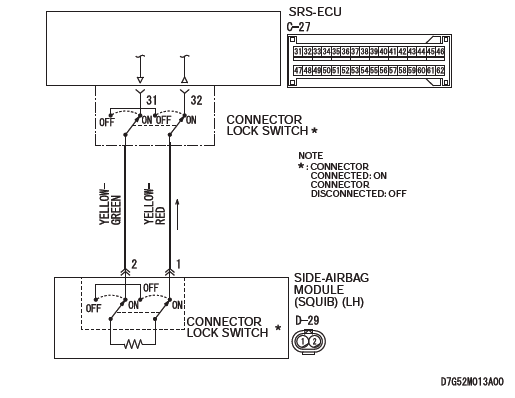
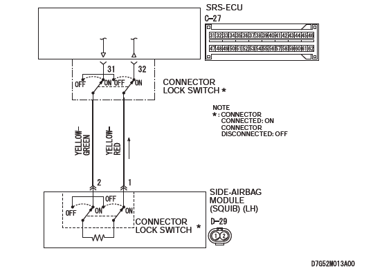
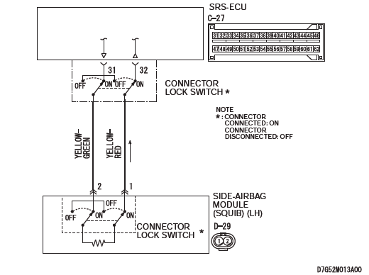
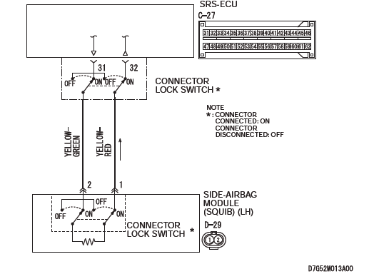
Side-Airbag Module (Squib) (LH) Circuit
CAUTION If DTC B1C27 is set in the SRS-ECU, always diagnose the CAN bus lines.
CIRCUIT OPERATION
- The SRS-ECU judges how severe a collision is by detecting signals from the side impact sensor installed on the lower side of the center pillar. If the impact is over a predetermined level, the SRS-ECU sends an ignition signal. At this time, if the side collision safing G-sensor is on, the SRS air bag will inflate.
- The ignition signal is input to the side-air bag module to inflate the side-air bag.
DTC SET CONDITIONS
This DTC is set if there is abnormal resistance between the input terminals of the side-air bag module (LH) (squib).
TROUBLESHOOTING HINTS
- Damaged wiring harnesses or connectors
- Short to ground in the left hand side-air bag module (squib) harness
- Malfunction of the SRS-ECU
DIAGNOSIS
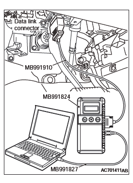
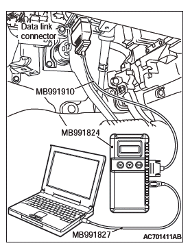
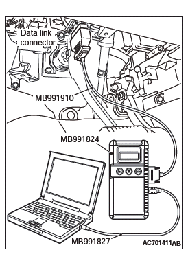
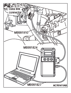
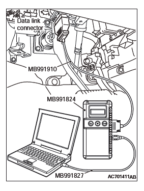
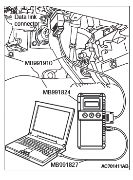
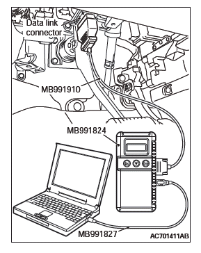
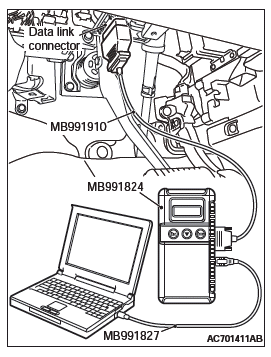
Required Special Tools:
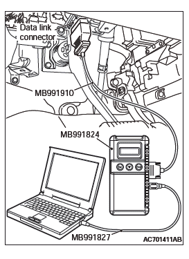
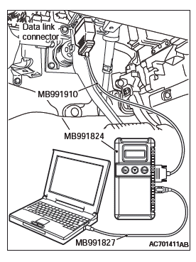
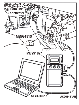
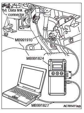
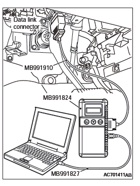
- MB991958: Scan Tool (M.U.T.-III Sub Assembly)
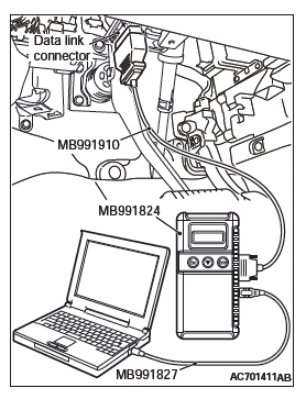
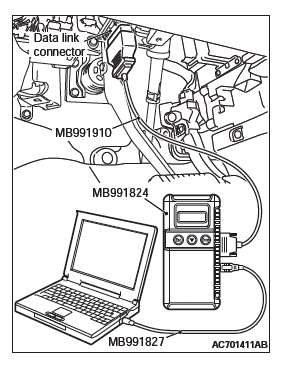
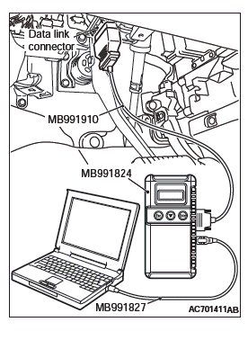
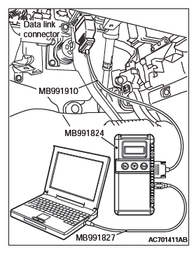
- MB991824: Vehicle Communication Interface (V.C.I.)
- MB991827: M.U.T.-III USB Cable
- MB991910: M.U.T.-III Main Harness A (Vehicles with CAN communication system)
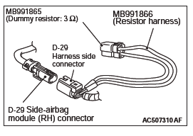
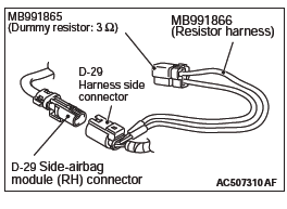
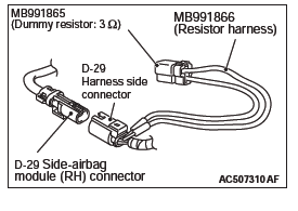
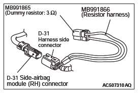
- MB991865: Dummy resistor
- MB991866: Resister harness
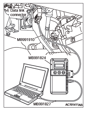
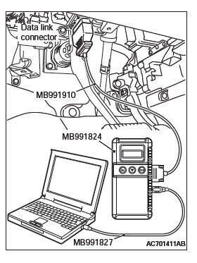
STEP 1. Using scan tool MB991958, diagnose the CAN bus line.
CAUTION To prevent damage to scan tool MB991958, always turn the ignition switch to the "LOCK" (OFF) position before connecting or disconnecting scan tool MB991958.
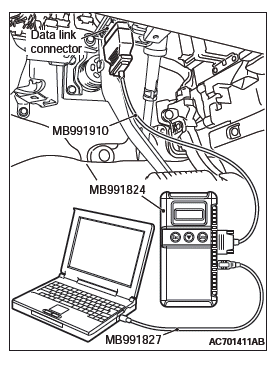
- Connect scan tool MB991958. Refer to "How to connect the scan tool".
- Turn the ignition switch to "ON" position.
- Diagnose the CAN bus line.
- Turn the ignition switch to the "LOCK" (OFF) position.
Q: Is the check result satisfactory?
YES : Go to Step 2.
NO : Repair the CAN bus line (Refer to GROUP 54C, Diagnosis).
STEP 2. Recheck for diagnostic trouble code.
Check again if the DTC is set.
- Erase the DTC.
- Turn the ignition switch to "ON" position.
- Check if the DTC is set.
- Turn the ignition switch to the "LOCK" (OFF) position.
Q: Is the DTC set?
YES : Go to Step 3.
NO : There is an intermittent malfunction such as poor engaged connector(s) or open circuit (Refer to GROUP 00, How to Cope with Intermittent Malfunction).
STEP 3. Check the side-air bag module (LH). (Using scan tool MB991958, read the diagnostic trouble code.)
- Disconnect the negative battery terminal.
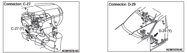
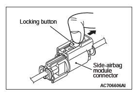
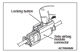
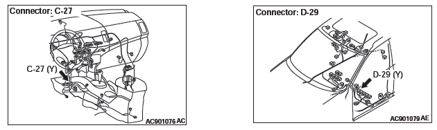
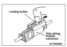
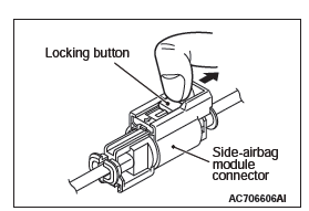
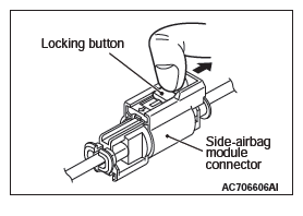
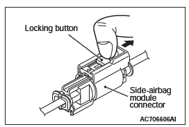
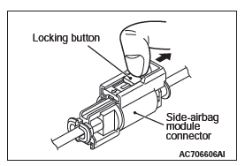
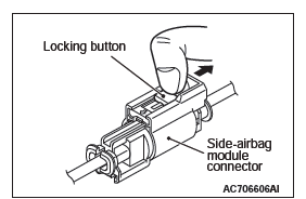
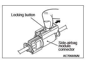
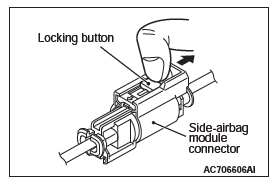
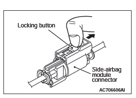
- Disconnect the D-29 side-airbag module connector, unlock the connector by sliding the locking button to the direction of the arrow as shown in the figure, and then disconnect the connector.
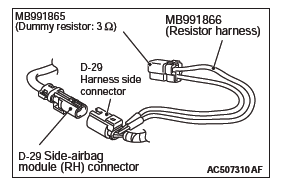
- Connect special tool MB991865 to special tool MB991866.
CAUTION Do not insert a test probe into the terminal from its front side directly, as the connector contact pressure may be weakened.
- Insert special tool MB991866 into the D-29 harness side connector by backprobing.
- Connect the negative battery terminal.
- Erase the diagnostic trouble code memory, and check the diagnostic trouble code.
Q: Is DTC B1C27 set?
YES : Go to Step 4.
NO : Replace the seatback assembly (Refer to GROUP 52A, Front Seat Assembly). Then go to Step 6.
STEP 4. Check the side-air bag module (LH) circuit.
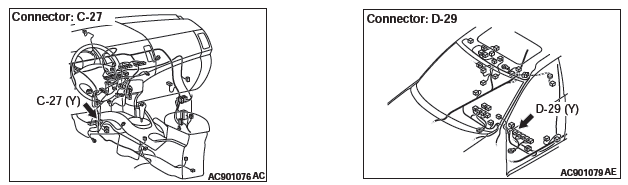
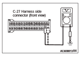
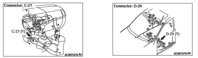
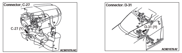
Measure the resistance at the SRS-ECU connector C-27.
- Disconnect the negative battery terminal.
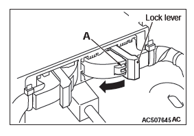
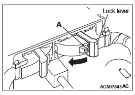
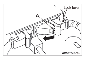
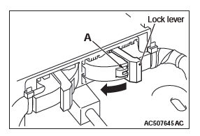
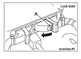
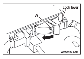
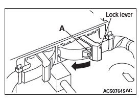
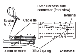
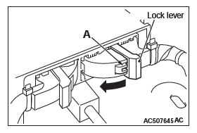
- While pushing the part "A" indicated in the figure of the harness side connector, turn the lock lever to the direction of the arrow to release the lock lever, and disconnect the C-27 SRS-ECU connector.
DANGER To prevent the air bag from deploying unintentionally, disconnect the side-airbag module (LH) connector D-29 to short the squib circuit.
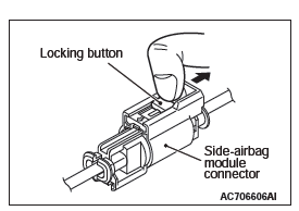
- Disconnect the D-29 side-airbag module connector, unlock the connector by sliding the locking button to the direction of the arrow as shown in the figure, and then disconnect the connector.
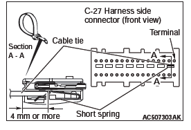
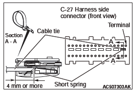
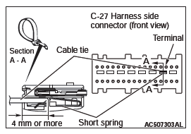
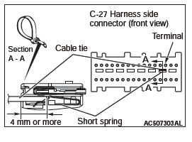
CAUTION Insert an insulator such as a cable tie to a depth of 4mm (0.16 inch) or more, otherwise the short spring will not be released.
- Insert a cable tie [3 mm (0.12 inch) wide, 0.5 mm (0.02 inch) thick] between terminals 31, 32 and the short spring to release the short spring.
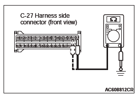
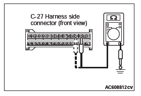
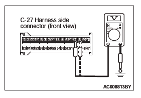
- Check for continuity between C-27 harness side connector
terminals 31, 32 and body ground.
It should be an open circuit.
Q: Is it open circuit?
YES : Erase the diagnostic trouble code from memory, and check the diagnostic trouble code. If DTC B1C27 sets, replace the SRS-ECU.
Then go to Step 6.
NO : Go to Step 5.
STEP 5. Check the harness wires for short circuit to ground between SRS-ECU connector C-27 (terminal No.31 and 32) and side-air bag module (LH) connector D-29 (terminal No.2 and 1).
Q: Is the check result normal?
YES : Go to Step 6.
NO : Repair the harness wires between SRS-ECU connector C-27 and side-air bag module (LH) connector D-29. Then go to Step 6.
STEP 6. Recheck for diagnostic trouble code.
Check again if the DTC is set.
- Erase the DTC.
- Turn the ignition switch to the "ON" position.
- Check if the DTC is set.
- Turn the ignition switch to the "LOCK" (OFF) position.
Q: Is DTC B1C27 set?
YES : Return to Step 1.
NO : The procedure is complete.
DTC B1C28: Side-air bag Module (LH) (Squib) System (Shorted to Squib Circuit Power Supply)
Side-Airbag Module (Squib) (LH) Circuit
CAUTION If DTC B1C28 is set in the SRS-ECU, always diagnose the CAN bus lines.
CIRCUIT OPERATION
- The SRS-ECU judges how severe a collision is by detecting signals from the side impact sensor installed on the lower side of the center pillar. If the impact is over a predetermined level, the SRS-ECU sends an ignition signal. At this time, if the side collision safing G-sensor is on, the SRS air bag will inflate.
- The ignition signal is input to the side-air bag module to inflate the side-air bag.
DTC SET CONDITIONS
This DTC is set if there is abnormal resistance between the input terminals of the side-air bag module (LH) (squib).
TROUBLESHOOTING HINTS
- Damaged wiring harnesses or connectors
- Short to the power supply in the side-air bag module (LH) (squib) harness
- Malfunction of the SRS-ECU
DIAGNOSIS
Required Special Tools:
- MB991958: Scan Tool (M.U.T.-III Sub Assembly)
- MB991824: Vehicle Communication Interface (V.C.I.)
- MB991827: M.U.T.-III USB Cable
- MB991910: M.U.T.-III Main Harness A (Vehicles with CAN communication system)
- MB991865: Dummy resistor
- MB991866: Resister harness
STEP 1. Using scan tool MB991958, diagnose the CAN bus line.
CAUTION To prevent damage to scan tool MB991958, always turn the ignition switch to the "LOCK" (OFF) position before connecting or disconnecting scan tool MB991958.
- Connect scan tool MB991958. Refer to "How to connect the scan tool".
- Turn the ignition switch to "ON" position.
- Diagnose the CAN bus line.
- Turn the ignition switch to the "LOCK" (OFF) position.
Q: Is the check result satisfactory?
YES : Go to Step 2.
NO : Repair the CAN bus line (Refer to GROUP 54C, Diagnosis).
STEP 2. Recheck for diagnostic trouble code.
Check again if the DTC is set.
- Erase the DTC.
- Turn the ignition switch to "ON" position.
- Check if the DTC is set.
- Turn the ignition switch to the "LOCK" (OFF) position.
Q: Is the DTC set?
YES : Go to Step 3.
NO : There is an intermittent malfunction such as poor engaged connector(s) or open circuit (Refer to GROUP 00, How to Cope with Intermittent Malfunction).
STEP 3. Check the side-air bag module (LH). (Using scan tool MB991958, read the diagnostic trouble code.)
- Disconnect the negative battery terminal.
- Disconnect the D-29 side-airbag module connector, unlock the connector by sliding the locking button to the direction of the arrow as shown in the figure, and then disconnect the connector.
- Connect special tool MB991865 to special tool MB991866.
CAUTION Do not insert a test probe into the terminal from its front side directly, as the connector contact pressure may be weakened.
- Insert special tool MB991866 into the D-29 harness side connector by backprobing.
- Connect the negative battery terminal.
- Erase the diagnostic trouble code memory, and check the diagnostic trouble code.
Q: Is DTC B1C28 set?
YES : Go to Step 4.
NO : Replace the seatback assembly (Refer to GROUP 52A, Front Seat Assembly). Then go to Step 6.
STEP 4. Check the side-air bag module (LH) circuit.
Measure the voltage at the SRS-ECU connector C-27.
- Disconnect the negative battery terminal.
- While pushing the part "A" indicated in the figure of the harness side connector, turn the lock lever to the direction of the arrow to release the lock lever, and disconnect the C-27 SRS-ECU connector.
DANGER To prevent the air bag from deploying unintentionally, disconnect the side-airbag module (LH) connector D-29 to short the squib circuit.
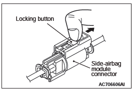
- Disconnect the D-29 side-airbag module connector, unlock the connector by sliding the locking button to the direction of the arrow as shown in the figure, and then disconnect the connector.
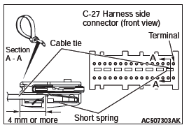
CAUTION Insert an insulator such as a cable tie to a depth of 4mm (0.16 inch) or more, otherwise the short spring will not be released.
- Insert a cable tie [3 mm (0.12 inch) wide, 0.5 mm (0.02 inch) thick] between terminals 31, 32 and the short spring to release the short spring.
- Connect the negative battery terminal.
- Ignition switch: "ON".
- Measure the voltage between C-27 harness side connector
terminals 31, 32 and body ground.
Voltage should measure 1 volt or less.
Q: Is the measured voltage within the specified range?
YES : Erase the diagnostic trouble code memory, and check the diagnostic trouble code. If DTC B1C28 sets, replace the SRS-ECU. Then go to Step 6.
NO : Go to Step 5.
STEP 5. Check the harness wires for short circuit to power supply between SRS-ECU connector C-27 (terminal No.31 and 32 and side-air bag module (LH) connector D-29 (terminal No.2 and 1).
Q: Is the check result normal?
YES : Go to Step 6.
NO : Repair the harness wires between SRS-ECU connector C-27 and side-air bag module (LH) connector D-29. Then go to Step 6.
STEP 6. Recheck for diagnostic trouble code.
Check again if the DTC is set.
- Erase the DTC.
- Turn the ignition switch to the "ON" position.
- Check if the DTC is set.
- Turn the ignition switch to the "LOCK" (OFF) position.
Q: Is DTC B1C28 set?
YES : Return to Step 1.
NO : The procedure is complete.
DTC B1C29: Side-air bag Module (LH) (Squib) System (Squib Circuit Open)
Side-Airbag Module (Squib) (LH) Circuit
CAUTION If DTC B1C29 is set in the SRS-ECU, always diagnose the CAN bus lines.
CIRCUIT OPERATION
- The SRS-ECU judges how severe a collision is by detecting signals from the side impact sensor installed on the lower side of the center pillar. If the impact is over a predetermined level, the SRS-ECU sends an ignition signal. At this time, if the side collision safing G-sensor is on, the SRS air bag will inflate.
- The ignition signal is input to the side-air bag module to inflate the side-air bag.
DTC SET CONDITIONS
This DTC is set if there is abnormal resistance between the input terminals of the side-air bag module (LH) (squib).
TROUBLESHOOTING HINTS
- Open circuit in the side-air bag module (squib) (LH) circuit
- Improper connector contact
- Malfunction of the SRS-ECU
DIAGNOSIS
Required Special Tools:
- MB991958: Scan Tool (M.U.T.-III Sub Assembly)
- MB991824: Vehicle Communication Interface (V.C.I.)
- MB991827: M.U.T.-III USB Cable
- MB991910: M.U.T.-III Main Harness A (Vehicles with CAN communication system)
- MB991865: Dummy resistor
- MB991866: Resister harness
STEP 1. Using scan tool MB991958, diagnose the CAN bus line.
CAUTION To prevent damage to scan tool MB991958, always turn the ignition switch to the "LOCK" (OFF) position before connecting or disconnecting scan tool MB991958.
- Connect scan tool MB991958. Refer to "How to connect the scan tool".
- Turn the ignition switch to "ON" position.
- Diagnose the CAN bus line.
- Turn the ignition switch to the "LOCK" (OFF) position.
Q: Is the check result satisfactory?
YES : Go to Step 2.
NO : Repair the CAN bus line (Refer to GROUP 54C, Diagnosis).
STEP 2. Recheck for diagnostic trouble code.
Check again if the DTC is set.
- Erase the DTC.
- Turn the ignition switch to "ON" position.
- Check if the DTC is set.
- Turn the ignition switch to the "LOCK" (OFF) position.
Q: Is the DTC set?
YES : Go to Step 3.
NO : There is an intermittent malfunction such as poor engaged connector(s) or open circuit (Refer to GROUP 00, How to Cope with Intermittent Malfunction).
STEP 3. Check the side-air bag module (LH). (Using scan tool MB991958, read the diagnostic trouble code.)
- Disconnect the negative battery terminal.
- Disconnect the D-29 side-airbag module connector, unlock the connector by sliding the locking button to the direction of the arrow as shown in the figure, and then disconnect the connector.
- Connect special tool MB991865 to special tool MB991866.
CAUTION Do not insert a test probe into the terminal from its front side directly, as the connector contact pressure may be weakened.
- Insert special tool MB991866 into the D-29 harness side connector by backprobing.
- Connect the negative battery terminal.
- Erase diagnostic trouble code memory, and then check the diagnostic trouble code.
Q: Is DTC B1C29 set?
YES : Go to Step 4.
NO : Replace the seatback assembly (Refer to GROUP 52A, Front Seat Assembly). Then go to Step 5.
STEP 4. Check the harness for open circuit between the SRS-ECU connector C-27 (terminal No.31 and 32) and the side-air bag module (LH) connector D-29 (terminal No.2 and 1).
- Disconnect the negative battery terminal.
- While pushing the part "A" indicated in the figure of the harness side connector, turn the lock lever to the direction of the arrow to release the lock lever, and disconnect the C-27 SRS-ECU connector.
DANGER To prevent the air bag from deploying unintentionally, disconnect the side-airbag module (LH) connector D-29 to short the squib circuit.
- Disconnect the D-29 side-airbag module connector, unlock the connector by sliding the locking button to the direction of the arrow as shown in the figure, and then disconnect the connector.
CAUTION Insert an insulator such as a cable tie to a depth of 4mm (0.16 inch) or more, otherwise the short spring will not be released.
- Insert a cable tie [3 mm (0.12 inch) wide, 0.5 mm (0.02 inch) thick] between terminals 31, 32 and the short spring to release the short spring.

CAUTION Do not insert a test probe into the terminal from D-29 harness side connector front side directly, as the connector contact pressure may be weakened.
- Check for continuity between the following terminals. It should be less than 2 ohms.
- SRS-ECU connector C-27 (terminal No.31) and the side-air bag module (LH) connector D-29 (terminal No.2)
- SRS-ECU connector C-27 (terminal No.32) and the side-air bag module (LH) connector D-29 (terminal No.1)
Q: Does continuity exist?
YES : Erase the diagnostic trouble code memory, and check the diagnostic trouble code. If DTC B1C29 sets, replace the SRS-ECU. Then go to Step 5.
NO : Repair the harness wires between SRS-ECU connector C-27 and side-air bag module (LH) connector D-29. Then go to Step 5.
STEP 5.Recheck for diagnostic trouble code.
Check again if the DTC is set.

- Erase the DTC.
- Turn the ignition switch to the "ON" position.
- Check if the DTC is set.
- Turn the ignition switch to the "LOCK" (OFF) position.
Q: Is DTC B1C29 set?
YES : Return to Step 1.
NO : The procedure is complete.
DTC B1C2A: Side-air bag Module (LH) (Squib) System (Short Circuit between Squib Circuit Terminals)
Side-Airbag Module (Squib) (LH) Circuit
CAUTION If DTC B1C2A is set in the SRS-ECU, always diagnose the CAN bus lines.
CIRCUIT OPERATION
- The SRS-ECU judges how severe a collision is by detecting signals from the side impact sensor installed on the lower side of the center pillar. If the impact is over a predetermined level, the SRS-ECU sends an ignition signal. At this time, if the side collision safing G-sensor is on, the SRS air bag will inflate.
- The ignition signal is input to the side-air bag module to inflate the side-air bag.
DTC SET CONDITIONS
This DTC is set if there is abnormal resistance between the input terminals of the side-air bag module (LH) (squib).
TROUBLESHOOTING HINTS
- Improper engaged connector or defective short spring*
- Short circuit between the side-air bag module (LH) (squib) circuit terminals
- Damaged connector(s)
- Malfunction of the SRS-ECU
NOTE: *: The squib circuit connectors integrate a "short" spring (which prevents the air bag from deploying unintentionally due to static electricity by shorting the positive wire to the ground wire in the squib circuit when the connectors are disconnected).
Therefore, if connector C-27 or D-29 is damaged or improperly engaged, the short spring may not be released when the connector is connected.
DIAGNOSIS
Required Special Tools:
- MB991958: Scan Tool (M.U.T.-III Sub Assembly)
- MB991824: Vehicle Communication Interface (V.C.I.)
- MB991827: M.U.T.-III USB Cable
- MB991910: M.U.T.-III Main Harness A (Vehicles with CAN communication system)
- MB991865: Dummy resistor
- MB991866: Resister harness
STEP 1. Using scan tool MB991958, diagnose the CAN bus line.
CAUTION To prevent damage to scan tool MB991958, always turn the ignition switch to the "LOCK" (OFF) position before connecting or disconnecting scan tool MB991958.
- Connect scan tool MB991958. Refer to "How to connect the scan tool".
- Connect scan tool MB991958 to the data link connector.
- Turn the ignition switch to "ON" position.
- Diagnose the CAN bus line.
Q: Is the check result satisfactory?
YES : Go to Step 2.
NO : Repair the CAN bus line (Refer to GROUP 54C, Diagnosis).
STEP 2. Recheck for diagnostic trouble code.
Check again if the DTC is set.

- Erase the DTC.
- Turn the ignition switch to "ON" position.
- Check if the DTC is set.
- Turn the ignition switch to the "LOCK" (OFF) position.
Q: Is the DTC set?
YES : Go to Step 3.
NO : There is an intermittent malfunction such as poor engaged connector(s) or open circuit (Refer to GROUP 00, How to Cope with Intermittent Malfunction).
STEP 3. Check SRS-ECU connector C-27 and side-air bag module (LH) connector D-29. (Using scan tool MB991958, read the diagnostic trouble code.)
- Disconnect the negative battery terminal.
- While pressing the part A in the illustration of the C-27 SRS-ECU harness side connector, turn the lock lever toward the arrow direction to release the lock lever. Then, disconnect the connector and reconnect it.
- Disconnect the D-29 side-airbag module connector, and then reconnect it. Unlock the connector by sliding the locking button to the direction of the arrow as shown in the figure, and then disconnect the connector.
- Connect the negative battery terminal.
- Erase the diagnostic trouble code memory, and check the diagnostic trouble code.
Q: Is DTC B1C2A out put?
YES : Go to Step 4.
NO : The procedure is complete. It is assumed that DTC B1C2A set because connector C-27 or D-29 was engaged improperly.
STEP 4. Check the side-air bag module (LH). (Using scan tool MB991958, read the diagnostic trouble code.)

- Disconnect the negative battery terminal.
- Disconnect the D-29 side-airbag module connector, unlock the connector by sliding the locking button to the direction of the arrow as shown in the figure, and then disconnect the connector.
- Connect special tool MB991865 to special tool MB991866.
CAUTION Do not insert a test probe into the terminal from its front side directly, as the connector contact pressure may be weakened.
- Insert special tool MB991866 into the D-29 harness side connector by backprobing.
- Connect the negative battery terminal.
- Erase diagnostic trouble code memory, and check the diagnostic trouble code.
Q: Is DTC B1C2A set?
YES : Go to Step 5.
NO : Replace the seatback assembly (Refer to GROUP 52A, Front Seat Assembly). Then go to Step 7.
STEP 5. Check the side-air bag module (LH) circuit.
Measure the resistance at the SRS-ECU connector C-27.
- Disconnect the negative battery terminal.
- While pushing the part "A" indicated in the figure of the harness side connector, turn the lock lever to the direction of the arrow to release the lock lever, and disconnect the C-27 SRS-ECU connector.
DANGER To prevent the air bag from deploying unintentionally, disconnect the side-airbag module (LH) connector D-29 to short the squib circuit.
- Disconnect the D-29 side-airbag module connector, unlock the connector by sliding the locking button to the direction of the arrow as shown in the figure, and then disconnect the connector.
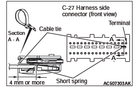
CAUTION Insert an insulator such as a cable tie to a depth of 4mm (0.16 inch) or more, otherwise the short spring will not be released.
- Insert a cable tie [3 mm (0.12 inch) wide, 0.5 mm (0.02 inch) thick] between terminals 31, 32 and the short spring to release the short spring.
- Check for continuity between C-27 harness side connector
terminals 31 and 32.
It should be an open circuit.
Q: Is it open circuit?
YES : Erase the diagnostic trouble code memory, and check the diagnostic trouble code. If DTC B1C2A sets, replace the SRS-ECU. Then go to Step 7.
NO : Go to Step 6.
STEP 6. Check the harness wires for short circuit between SRS-ECU connector C-27 (terminal No.31 and 32) and side-air bag module (LH) connector D-29 (terminal No.2 and 1).
Q: Is the check result normal?
YES : Go to Step 7.
NO : Repair the harness wires between SRS-ECU connector C-27 and side-air bag module (LH) connector D-29. Then go to Step 7.
STEP 7. Recheck for diagnostic trouble code.
Check again if the DTC is set.
- Erase the DTC.
- Turn the ignition switch to the "ON" position.
- Check if the DTC is set.
- Turn the ignition switch to the "LOCK" (OFF) position.
Q: Is DTC B1C2A set?
YES : Return to Step 1.
NO : The procedure is complete.
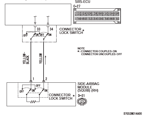
DTC B1C2B: Side-air bag Module (RH) (Squib) System (Shorted to Squib Circuit Ground)
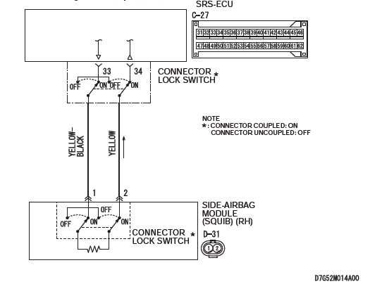
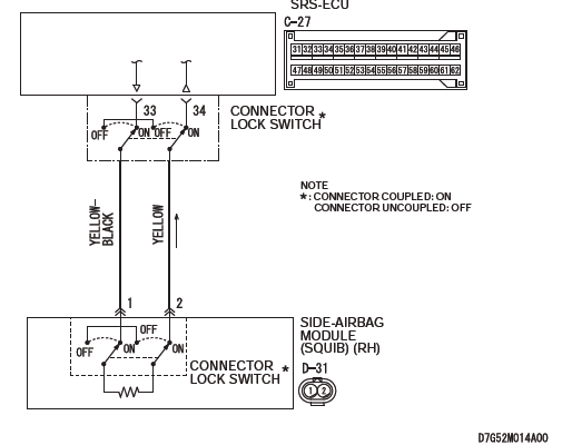
Side-Airbag Module (Squib) (RH) Circuit
CAUTION If DTC B1C2B is set in the SRS-ECU, always diagnose the CAN bus lines.
CIRCUIT OPERATION
- The SRS-ECU judges how severe a collision is by detecting signals from the side impact sensor installed on the lower side of the center pillar. If the impact is over a predetermined level, the SRS-ECU sends an ignition signal. At this time, if the side collision safing G-sensor is on, the SRS air bag will inflate.
- The ignition signal is input to the side-air bag module to inflate the side-air bag.
DTC SET CONDITIONS
This DTC is set if there is abnormal resistance between the input terminals of the side-air bag module (RH) (squib).
TROUBLESHOOTING HINTS
- Damaged wiring harnesses or connectors
- Short to ground in the side-air bag module (RH) (squib) harness
- Malfunction of the SRS-ECU
DIAGNOSIS
Required Special Tools:
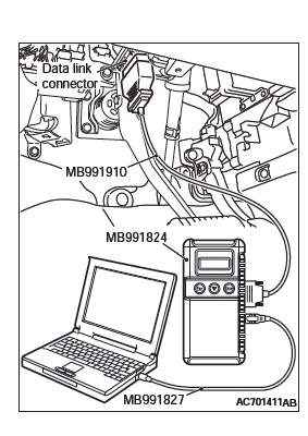
- MB991958: Scan Tool (M.U.T.-III Sub Assembly)
- MB991824: Vehicle Communication Interface (V.C.I.)
- MB991827: M.U.T.-III USB Cable
- MB991910: M.U.T.-III Main Harness A (Vehicles with CAN Communication System)
- MB991865: Dummy resistor
- MB991866: Resister harness
STEP 1. Using scan tool MB991958, diagnose the CAN bus line.
CAUTION To prevent damage to scan tool MB991958, always turn the ignition switch to the "LOCK" (OFF) position before connecting or disconnecting scan tool MB991958.
- Connect scan tool MB991958. Refer to "How to connect the scan tool".
- Turn the ignition switch to "ON" position.
- Diagnose the CAN bus line.
- Turn the ignition switch to the "LOCK" (OFF) position.
Q: Is the check result satisfactory?
YES : Go to Step 2.
NO : Repair the CAN bus line (Refer to GROUP 54C, Diagnosis).
STEP 2. Recheck for diagnostic trouble code.
Check again if the DTC is set.
- Erase the DTC.
- Turn the ignition switch to "ON" position.
- Check if the DTC is set.
- Turn the ignition switch to the "LOCK" (OFF) position.
Q: Is the DTC set?
YES : Go to Step 3.
NO : There is an intermittent malfunction such as poor engaged connector(s) or open circuit (Refer to GROUP 00, How to Cope with Intermittent Malfunction).
STEP 3. Check the side-air bag module (RH). (Using scan tool MB991958, read the diagnostic trouble code.)
- Disconnect the negative battery terminal.
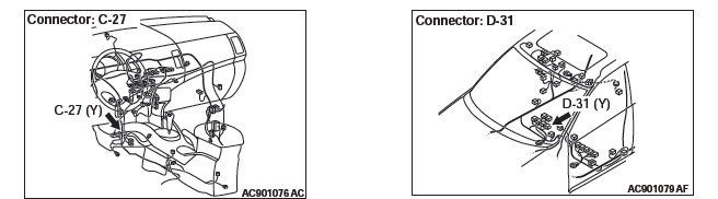
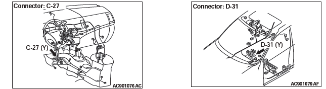
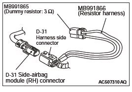
- Disconnect the D-31 side-airbag module connector, unlock the connector by sliding the locking button to the direction of the arrow as shown in the figure, and then disconnect the connector.
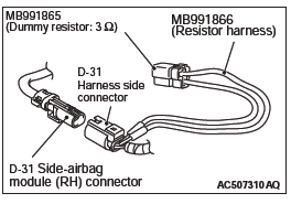
- Connect special tool MB991865 to special tool MB991866.
CAUTION Do not insert a test probe into the terminal from its front side directly, as the connector contact pressure may be weakened.
- Insert special tool MB991866 into the D-31 harness side connector by backprobing.
- Connect the negative battery terminal.
- Erase the diagnostic trouble code memory, and check the diagnostic trouble code.
Q: Is DTC B1C2B set?
YES : Go to Step 4.
NO : Replace the seatback assembly (Refer to GROUP 52A, Front Seat Assembly). Then go to Step 6.
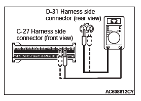
STEP 4. Check the side-air bag module (RH) circuit.
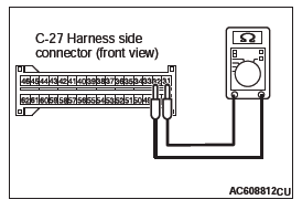
Measure the resistance at the SRS-ECU connector C-27.
- Disconnect the negative battery terminal.
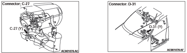
- While pushing the part "A" indicated in the figure of the harness side connector, turn the lock lever to the direction of the arrow to release the lock lever, and disconnect the C-27 SRS-ECU connector.
DANGER To prevent the air bag from deploying unintentionally, disconnect the side-airbag module (RH) connector D-31 to short the squib circuit.
- Disconnect the D-31 side-airbag module connector, unlock the connector by sliding the locking button to the direction of the arrow as shown in the figure, and then disconnect the connector.
CAUTION Insert an insulator such as a cable tie to a depth of 4mm (0.16 inch) or more, otherwise the short spring will not be released.
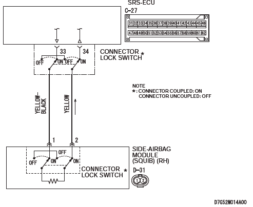
- Insert a cable tie [3 mm (0.12 inch) wide, 0.5 mm (0.02 inch) thick] between terminals 33, 34 and the short spring to release the short spring.
- Check for continuity between C-27 harness side connector
terminals 33, 34 and body ground.
It should be an open circuit.
Q: Is it open circuit?
YES : Erase the diagnostic trouble code memory, and check the diagnostic trouble code. If DTC B1C2B sets, replace the SRS-ECU. Then go to Step 6.
NO : Go to Step 5.
STEP 5. Check the harness wires for short circuit to ground between SRS-ECU connector C-27 (terminal No.33 and 34) and side-air bag module (RH) connector D-31 (terminal No.1 and 2).
Q: Is the check result normal?
YES : Go to Step 6.
NO : Repair the harness wires between SRS-ECU connector C-27 and side-air bag module (RH) connector D-31. Then go to Step 6.
STEP 6. Recheck for diagnostic trouble code.
Check again if the DTC is set.
- Erase the DTC.
- Turn the ignition switch to the "ON" position.
- Check if the DTC is set.
- Turn the ignition switch to the "LOCK" (OFF) position.
Q: Is DTC B1C2B set?
YES : Return to Step 1.
NO : The procedure is complete.
DTC B1C2C: Side-air bag Module (RH) (Squib) System (Shorted to Squib Circuit Power Supply)
Side-Airbag Module (Squib) (RH) Circuit
CAUTION If DTC B1C2C is set in the SRS-ECU, always diagnose the CAN bus lines.
CIRCUIT OPERATION
- The SRS-ECU judges how severe a collision is by detecting signals from the side impact sensor installed on the lower side of the center pillar. If the impact is over a predetermined level, the SRS-ECU sends an ignition signal. At this time, if the side collision safing G-sensor is on, the SRS air bag will inflate.
- The ignition signal is input to the side-air bag module to inflate the side-air bag.
DTC SET CONDITIONS
This DTC is set if there is abnormal resistance between the input terminals of the side-air bag module (RH) (squib).
TROUBLESHOOTING HINTS
- Damaged wiring harnesses or connectors
- Short to the power supply in the side-air bag module (RH) (squib) harness
- Malfunction of the SRS-ECU
DIAGNOSIS
Required Special Tools:
- MB991958: Scan Tool (M.U.T.-III Sub Assembly)
- MB991824: Vehicle Communication Interface (V.C.I.)
- MB991827: M.U.T.-III USB Cable
- MB991910: M.U.T.-III Main Harness A (Vehicles with CAN Communication System)
- MB991865: Dummy resistor
- MB991866: Resister harness
STEP 1. Using scan tool MB991958, diagnose the CAN bus line.
CAUTION To prevent damage to scan tool MB991958, always turn the ignition switch to the "LOCK" (OFF) position before connecting or disconnecting scan tool MB991958.
- Connect scan tool MB991958.
- Turn the ignition switch to "ON" position.
- Diagnose the CAN bus line.
- Turn the ignition switch to the "LOCK" (OFF) position.
Q: Is the check result satisfactory?
YES : Go to Step 2.
NO : Repair the CAN bus line (Refer to GROUP 54C, Diagnosis).
STEP 2. Recheck for diagnostic trouble code.
Check again if the DTC is set.
- Erase the DTC.
- Turn the ignition switch to "ON" position.
- Check if the DTC is set.
- Turn the ignition switch to the "LOCK" (OFF) position.
Q: Is the DTC set?
YES : Go to Step 3.
NO : There is an intermittent malfunction such as poor engaged connector(s) or open circuit (Refer to GROUP 00, How to Cope with Intermittent Malfunction).
STEP 3. Check the side-air bag module (RH). (Using scan tool MB991958, read the diagnostic trouble code.)
- Disconnect the negative battery terminal.
- Disconnect the D-31 side-airbag module connector, unlock the connector by sliding the locking button to the direction of the arrow as shown in the figure, and then disconnect the connector.
- Connect special tool MB991865 to special tool MB991866.
CAUTION Do not insert a test probe into the terminal from its front side directly, as the connector contact pressure may be weakened.
- Insert special tool MB991866 into the D-31 harness side connector by backprobing.
- Connect the negative battery terminal.
- Erase the diagnostic trouble code memory, and check the diagnostic trouble code.
Q: Is DTC B1C2C set?
YES : Go to Step 4.
NO : Replace the seatback assembly (Refer to GROUP 52A, Front Seat Assembly). Then go to Step 5.
STEP 4. Check the side-air bag module (RH) circuit.
Measure the voltage at the SRS-ECU connector C-27.
- Disconnect the negative battery terminal.
- While pushing the part "A" indicated in the figure of the harness side connector, turn the lock lever to the direction of the arrow to release the lock lever, and disconnect the C-27 SRS-ECU connector.

DANGER To prevent the air bag from deploying unintentionally, disconnect the side-airbag module (RH) connector D-31 to short the squib circuit.
- Disconnect the D-31 side-airbag module connector, unlock the connector by sliding the locking button to the direction of the arrow as shown in the figure, and then disconnect the connector.
CAUTION Insert an insulator such as a cable tie to a depth of 4mm (0.16 inch) or more, otherwise the short spring will not be released.
- Insert a cable tie [3 mm (0.12 inch) wide, 0.5 mm (0.02 inch) thick] between terminals 33, 34 and the short spring to release the short spring.
- Connect the negative battery terminal.
- Ignition switch: "ON".
- Measure the voltage between C-27 harness side connector terminals 33 and 34 and body ground.
Voltage should measure 1 volt or less.
Q: Is the measured voltage within the specified range?
YES : Erase the diagnostic trouble code memory, and check the diagnostic trouble code. If DTC B1C2C sets, replace the SRS-ECU. Then go to Step 6.
NO : Go to Step 5.
STEP 5. Check the harness wires for short circuit to power supply between SRS-ECU connector C-27 (terminal No.33 and 34) and side-air bag module (RH) connector D-31 (terminal No.1 and 2).
Q: Is the check result normal?
YES : Go to Step 6.
NO : Repair the harness wires between SRS-ECU connector C-27 and side-air bag module (RH) connector D-31. Then go to Step 6.
STEP 6. Recheck for diagnostic trouble code.
Check again if the DTC is set.
- Erase the DTC.
- Turn the ignition switch to the "ON" position.
- Check if the DTC is set.
- Turn the ignition switch to the "LOCK" (OFF) position.
Q: Is DTC B1C2C set?
YES : Return to Step 1.
NO : The procedure is complete.
DTC B1C2D: Side-air bag Module (RH) (Squib) System (Squib Circuit Open)
Side-Airbag Module (Squib) (RH) Circuit
CAUTION If DTC B1C2D is set in the SRS-ECU, always diagnose the CAN bus lines.
CIRCUIT OPERATION
- The SRS-ECU judges how severe a collision is by detecting signals from the side impact sensor installed on the lower side of the center pillar. If the impact is over a predetermined level, the SRS-ECU sends an ignition signal. At this time, if the side collision safing G-sensor is on, the SRS air bag will inflate.
- The ignition signal is input to the side-air bag module to inflate the side-air bag.
DTC SET CONDITIONS
This DTC is set if there is abnormal resistance between the input terminals of the side-air bag module (RH) (squib).
TROUBLESHOOTING HINTS
- Open circuit in the side-air bag module (RH) (squib) circuit
- Improper connector contact
- Malfunction of the SRS-ECU
DIAGNOSIS
Required Special Tools:
- MB991958: Scan Tool (M.U.T.-III Sub Assembly)
- MB991824: Vehicle Communication Interface (V.C.I.)
- MB991827: M.U.T.-III USB Cable
- MB991910: M.U.T.-III Main Harness A (Vehicles with CAN Communication System)
- MB991865: Dummy resistor
- MB991866: Resister harness
STEP 1. Using scan tool MB991958, diagnose the CAN bus line.
CAUTION To prevent damage to scan tool MB991958, always turn the ignition switch to the "LOCK" (OFF) position before connecting or disconnecting scan tool MB991958.
- Connect scan tool MB991958. Refer to "How to connect the scan tool".
- Turn the ignition switch to "ON" position.
- Diagnose the CAN bus line.
- Turn the ignition switch to the "LOCK" (OFF) position.
Q: Is the check result satisfactory?
YES : Go to Step 2.
NO : Repair the CAN bus line (Refer to GROUP 54C, Diagnosis).
STEP 2. Recheck for diagnostic trouble code.
Check again if the DTC is set.
- Erase the DTC.
- Turn the ignition switch to "ON" position.
- Check if the DTC is set.
- Turn the ignition switch to the "LOCK" (OFF) position.
Q: Is the DTC set?
YES : Go to Step 3.
NO : There is an intermittent malfunction such as poor engaged connector(s) or open circuit (Refer to GROUP 00, How to Cope with Intermittent Malfunction.
STEP 3. Check the side-air bag module (RH). (Using scan tool MB991958, read the diagnostic trouble code.)
- Disconnect the negative battery terminal.
- Disconnect the D-31 side-airbag module connector, unlock the connector by sliding the locking button to the direction of the arrow as shown in the figure, and then disconnect the connector.
- Connect special tool MB991865 to special tool MB991866.
CAUTION Do not insert a test probe into the terminal from its front side directly, as the connector contact pressure may be weakened.
- Insert special tool MB991866 into the D-31 harness side connector by backprobing.
- Connect the negative battery terminal.
- Erase the diagnostic trouble code memory, and check the diagnostic trouble code.
Q: Is DTC B1C2D set?
YES : Go to Step 4.
NO : Replace the seatback assembly. Then go to Step 5.
STEP 4. Check the harness for open circuit between SRS-ECU connector C-27 (terminal No.33 and 34) and the side-air bag module (RH) connector D-31 (terminal No.1 and 2).
- Disconnect the negative battery terminal.
- While pushing the part "A" indicated in the figure of the harness side connector, turn the lock lever to the direction of the arrow to release the lock lever, and disconnect the C-27 SRS-ECU connector.
DANGER To prevent the air bag from deploying unintentionally, disconnect the side-airbag module (RH) connector D-31 to short the squib circuit.
- Disconnect the D-31 side-airbag module connector, unlock the connector by sliding the locking button to the direction of the arrow as shown in the figure, and then disconnect the connector.
CAUTION Insert an insulator such as a cable tie to a depth of 4mm (0.16 inch) or more, otherwise the short spring will not be released.
- Insert a cable tie [3 mm (0.12 inch) wide, 0.5 mm (0.02 inch) thick] between terminals 33, 34 and the short spring to release the short spring.
CAUTION Do not insert a test probe into the terminal from D-31 harness side connector front side directly, as the connector contact pressure may be weakened.
- Check for continuity between the following terminals. It should be less than 2 ohms.
- SRS-ECU connector C-27 (terminal No.33) and the side-air bag module (RH) connector D-31 (terminal No.1)
- SRS-ECU connector C-27 (terminal No.34) and the side-air bag module (RH) connector D-31 (terminal No.2)
Q: Does continuity exist?
YES : Erase the diagnostic trouble code memory, and check the diagnostic trouble code. If DTC B1C2D sets, replace the SRS-ECU. Then go to Step 5.
NO : Repair the harness wires between SRS-ECU connector C-27 and side-air bag module (RH) connector D-31. Then go to Step 5.
STEP 5. Recheck for diagnostic trouble code.
Check again if the DTC is set.
- Erase the DTC.
- Turn the ignition switch to the "ON" position.
- Check if the DTC is set.
- Turn the ignition switch to the "LOCK" (OFF) position.
Q: Is DTC B1C2D set?
YES : Return to Step 1.
NO : The procedure is complete.
DTC B1C2E: Side-air bag Module (RH) (Squib) System (Short Circuit between Squib Circuit Terminals)
Side-Airbag Module (Squib) (RH) Circuit
CAUTION If DTC B1C2E is set in the SRS-ECU, always diagnose the CAN bus lines.
CIRCUIT OPERATION
- The SRS-ECU judges how severe a collision is by detecting signals from the side impact sensor installed on the lower side of the center pillar. If the impact is over a predetermined level, the SRS-ECU sends an ignition signal. At this time, if the side collision safing G-sensor is on, the SRS air bag will inflate.
- The ignition signal is input to the side-air bag module to inflate the side-air bag.
DTC SET CONDITIONS
This DTC is set if there is abnormal resistance between the input terminals of the side-air bag module (RH) (squib).
TROUBLESHOOTING HINTS
- Improper engaged connector or defective short spring*
- Short between the side-air bag module (RH) (squib) circuit terminals
- Damaged connector(s)
- Malfunction of the SRS-ECU
NOTE: *: The squib circuit connectors integrate a "short" spring (which prevents the air bag from deploying unintentionally due to static electricity by shorting the positive wire to the ground wire in the squib circuit when the connectors are disconnected). Therefore, if connector C-27 or D-31 is damaged or improperly engaged, the short spring may not be released when the connector is connected.
DIAGNOSIS
Required Special Tools:
- MB991958: Scan Tool (M.U.T.-III Sub Assembly)
- MB991824: Vehicle Communication Interface (V.C.I.)
- MB991827: M.U.T.-III USB Cable
- MB991910: M.U.T.-III Main Harness A (Vehicles with CAN communication system)
- MB991865: Dummy resister
- MB991866: Resister harness
STEP 1. Using scan tool MB991934, diagnose the CAN bus line.
CAUTION To prevent damage to scan tool MB991934, always turn the ignition switch to the "LOCK" (OFF) position before connecting or disconnecting scan tool MB991934.
- Connect scan tool MB991934. Refer to "How to connect the scan tool".
- Turn the ignition switch to "ON" position.
- Diagnose the CAN bus line.
- Turn the ignition switch to the "LOCK" (OFF) position.
Q: Is the check result satisfactory?
YES : Go to Step 2.
NO : Repair the CAN bus line.
STEP 2. Recheck for diagnostic trouble code.
Check again if the DTC is set.
- Erase the DTC.
- Turn the ignition switch to "ON" position. <
READ NEXT:
 DTC B1C33, B1C34, B1C35, B1C36, B1C38, B1C39, B1C3A, B1C3B
DTC B1C33: Driver's Lap Pre-tensioner (Squib) System (Shorted to Squib
Circuit Ground)
Driver's Lap pre-tensioner (Squib) Circuit
CAUTION
If DTC B1C33 is set in the SRS-ECU, always diagnose
the CAN
DTC B1C47, B1C48, B1C49, B1C4A, B210D, B212C, B212D
DTC B1C47: Front Passenger's Seat Belt Pre-tensioner (Squib) System
(Shorted to Squib Circuit
Ground)
Seat Belt Pre-Tensioner (passenger's side) (Squib) Circuit
CAUTION
If DTC B1C47 is set in the S
DTC U0019, U0141, U0154, U0155, U0164, U0168, U0170, U0171, U0172, U0173, U0175,
U0176, U0184, U0195, U0212, U1414, U1415
DTC U0019: Bus Off (CAN-B)
CAUTION
If the DTC U0019 is set, be sure to diagnose
the CAN main bus line.
When replacing the ECU, always check that
the communication circuit is normal.
DTC SET COND
SEE MORE:
Door Assembly, Door Glass and Regulator, Door Handle and Latch
Door Assembly
REMOVAL AND INSTALLATION
Post-installation operation
Door adjustment
<Front door>
Damper removal
Damper
Door assembly and front door
hinge removal steps
Front scuff plate, cowl side trim
Wiring harness connector
connection
Door check connecting bolt
Door assembly
Combination headlamps and dipper switch
Headlamps
NOTE:
● Do not leave the lights on for a long time while the engine is stationary (not
running). A rundown battery could result.
● When it rains, or when the vehicle has been washed, the inside of the lens
sometimes becomes foggy, but this does not indicate a functional
